SmartOnline BP192V12RT3US - Battery Tripp Lite - Free user manual and instructions
Find the device manual for free SmartOnline BP192V12RT3US Tripp Lite in PDF.

User questions about SmartOnline BP192V12RT3US Tripp Lite
0 question about this device. Answer the ones you know or ask your own.
Ask a new question about this device
Download the instructions for your Battery in PDF format for free! Find your manual SmartOnline BP192V12RT3US - Tripp Lite and take your electronic device back in hand. On this page are published all the documents necessary for the use of your device. SmartOnline BP192V12RT3US by Tripp Lite.
USER MANUAL SmartOnline BP192V12RT3US Tripp Lite
External Battery Packs
Not suitable for mobile applications.
Introduction 2
Important Safety Instructions 2
Mounting 3
Connection 9
Maintenance 10
Warranty and Product Registration 11
Español 12
Français 23
Русский 34
PROTECT YOUR INVESTMENT!
Register your product for quicker service and ultimate peace of mind.
You could also win an ISOBAR6ULTRA surge protector— a \$100 value!

text_image
QR code image containing encoded data, no visible human-readable textwww.tripplite.com/warranty

text_image
TRIPP·LITE
Manufacturing Excellence.
1111 W. 35th Street, Chicago, IL 60609 USA • www.tripplite.com/support
Copyright © 2018 Tripp Lite. All rights reserved.
Introduction
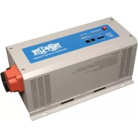
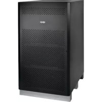
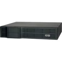
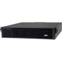
Tripp Lite BP Series External Battery Packs are designed for use with various Tripp Lite UPS systems equipped with external battery pack connectors.
Important Safety Instructions

SAVE THESE INSTRUCTIONS
WARNING! The mounting shelves are not intended to support more than one battery pack. Do not stack multiple battery packs on a single set of mounting shelves. Failure to follow this warning may lead to product damage and/or risk of personal bodily harm.
- Use caution when lifting battery packs. Because of the considerable weight of all battery packs, at least two people should assist in lifting and installing them.
- Make certain the battery packs and UPS use the same DC voltage before connecting them.
- Use of this equipment in life support applications where failure of this equipment can reasonably be expected to cause the failure of the life support equipment or to significantly affect its safety or effectiveness is not recommended.
- Suggested mounting procedures are for common rack types and may not be appropriate for all rack configurations. User must determine the fitness of rack and wall-mount hardware and procedures before mounting.
- When connecting multiple battery packs to a single UPS, the battery packs should be approximately the same age.
- It is normal for sparks to occur when connecting external batteries.
- Do not unplug external batteries from the UPS while the UPS is operating on battery power, due to the possibility of dangerous arcing.
- Batteries can present a risk of electrical shock and burn from high short-circuit current. Observe proper precautions. Do not dispose of the batteries in a fire. Do not open the UPS or batteries. Do not short or bridge the battery terminals with any object. Unplug and turn off the UPS before performing battery replacement. Use tools with insulated handles. There are no user-serviceable parts inside the UPS. Battery replacement should be performed only by authorized service personnel using the same number and type of batteries (Sealed Lead-Acid). The batteries are recyclable. Refer to your local codes for disposal requirements or visit http://www.tripplite.com/support/recycling-program for recycling information. Tripp Lite offers a complete line of UPS System Replacement Battery Cartridges (R.B.C.). Visit Tripp Lite on the Web at http://www.tripplite.com/products/battery-finder/ to locate the specific replacement battery for your UPS.
Mounting (4-Post Rack)
Mount your battery pack in a 4-post or 2-post rack or rack enclosure, or in an upright tower position. The user must determine the fitness of hardware and procedures before mounting. If hardware and procedures are not suitable for your application, contact the manufacturer of your rack or rack enclosure. The procedures described in this manual are for common rack and rack enclosure types and may not be appropriate for all applications.
4-Post Mounting
Most external battery packs include the hardware required for 4-post mounting. If this hardware did not come with your unit, an Adjustable 4-Post Rack-mount Shelf Kit (models: 4POSTRAILKIT or 4POSTRAILKITHD) may be ordered separately.
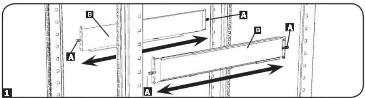
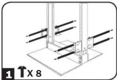
1 The included plastic pegsA will temporarily support the empty rack-mount shelves B while you install the permanent mounting hardware. Insert a peg near the center of the front and rear bracket of each shelf as shown. (Each front bracket has six holes and each rear bracket has three holes.) The pegs will snap into place.
After installing the pegs, expand each shelf to match the depth of your rack rails. The pegs will fit through the square holes in the rack rails to support the shelves. Refer to the rack unit labels to confirm the shelves are level in all directions.
Note: The support ledge of each shelf must face inward.
text_image
A B A B A 1Mounting (4-Post Rack)
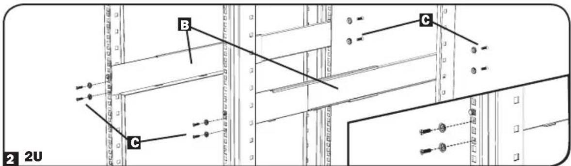
2 Secure the shelves B to the mounting rails permanently using the included screws and cup washers C as shown.
- For 2U equipment mounting, place four screws total in the front and four screws total in the back. - For 3U equipment mounting, place six screws total in the front and four screws total in the back.
Tighten all screws before proceeding.

Warning: Do not attempt to install equipment until you have inserted and tightened the required screws. The plastic pegs will not support the weight of your equipment.
text_image
2 2U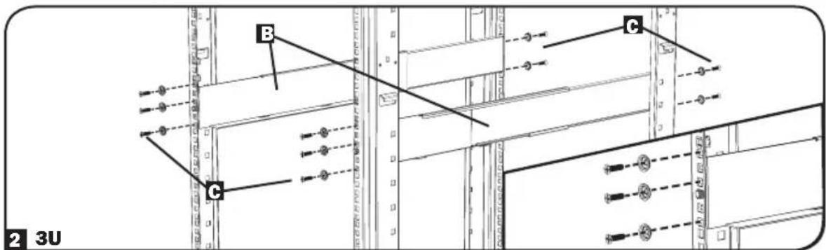
text_image
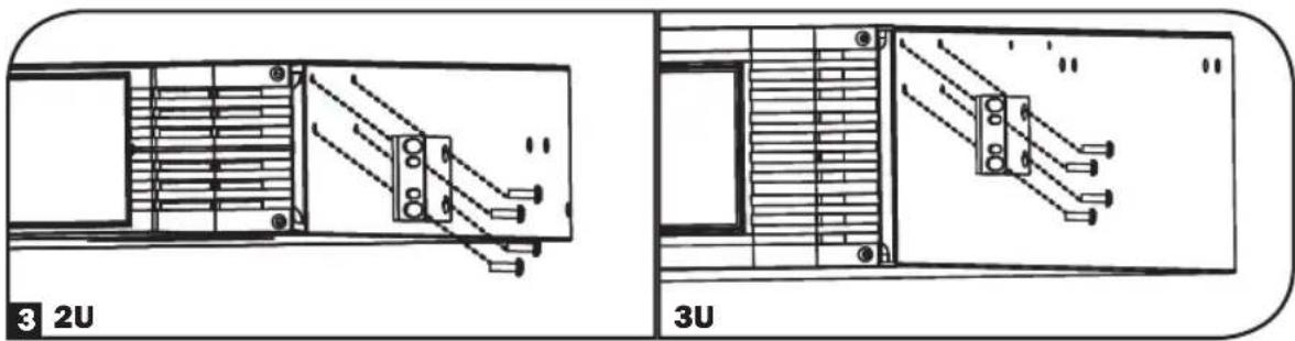
B C 2 3U3 Using the included hardware, attach the mounting brackets to the forward mounting holes of the cabinet. The mounting bracket "ears" should face forward. (Some equipment may have pre-installed or integrated mounting brackets.)
text_image
3 2U 3UMounting (4-Post Rack)
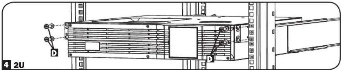
4 With the aid of an assistant (if necessary), lift your equipment and slide it into the shelves. Attach the equipment mounting brackets to the forward mounting rails with user-supplied screws and washers D. Tighten all screws securely.
text_image
4 2U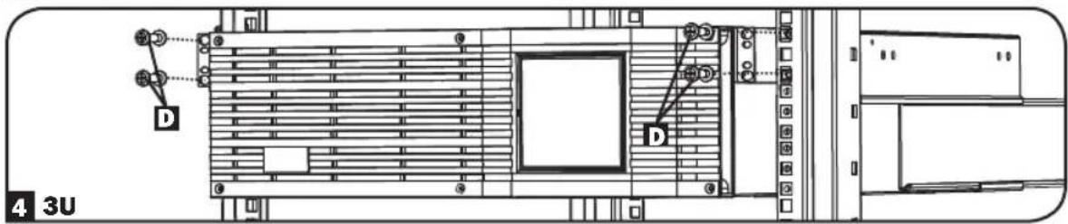
text_image
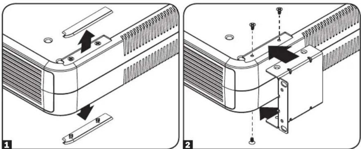
D D 4 3UBP24V15RT2U 4-Post Mounting
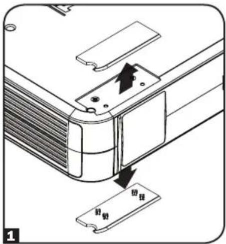
To install the BP24V15RT2U external battery pack in a 4-post rack, remove the mounting hole covers from the top and bottom sides of the battery pack 1. To install the battery pack in a 4-post rack, attach the mounting ears to each side of the UPS using the included hardware 2. With the help of an assistant, lift the battery pack and attach it to a standard rack with user-supplied hardware 3.
text_image
Technical diagram showing two views of a device's internal structure with labeled parts and directional arrows indicating assembly or repair.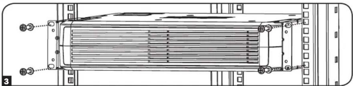
natural_image
Technical line drawing of a heat exchanger or radiator assembly with mounting flanges and cooling fins (no text or symbols)Mounting (2-Post Rack or Tower)
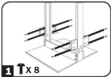
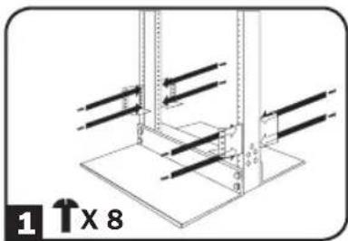
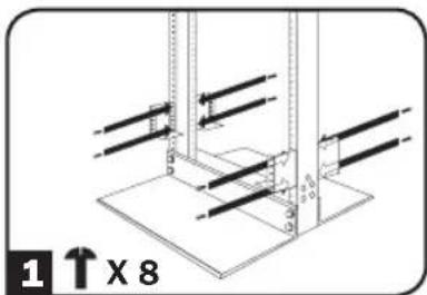
2-Post (Telecom) Mounting
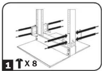
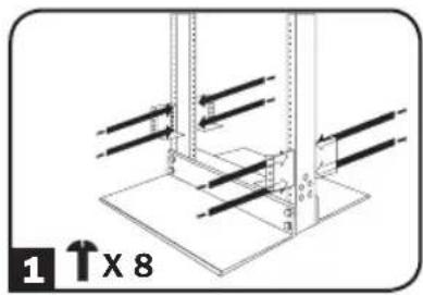
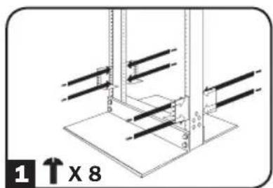
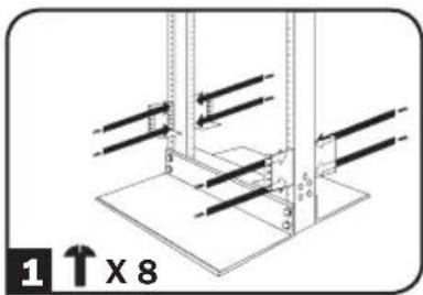
Select external battery pack models include the hardware required for 2-post mounting. If this hardware did not come with your unit, a 2-Post Rackmount Installation Kit (Model 2POSTRMKITWM or 2POSTRMKITHD) may be ordered separately. Refer to the illustrations below for specific installation instructions covering 2U, 3U and 4U battery packs.
2U
natural_image
Technical diagram of a mechanical assembly with vertical supports and mounting base (no text or symbols)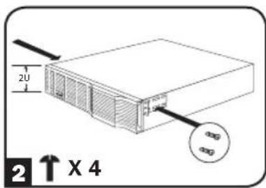
text_image
2U 2X4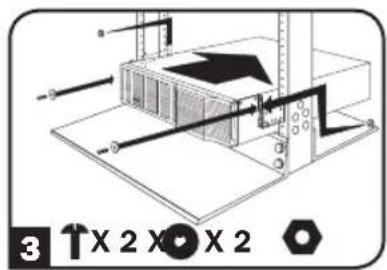
text_image
3 X 2 X 2 X 23U
text_image
1 ↑x 8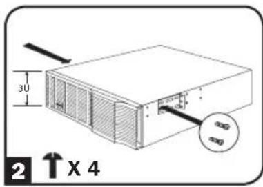
text_image
30 2 ↑ X 4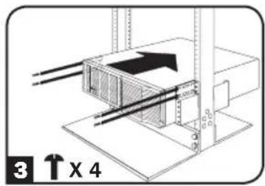
text_image
3 ↑ x 44U
natural_image
Technical diagram of a mechanical assembly with vertical supports and mounting base (no text or symbols)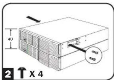
text_image
4U 2 ↑ X 4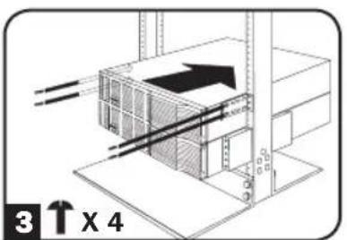
text_image
3 ↑ X 4Mounting (2-Post Rack or Tower)
BP24V15RT2U 2-Post Mounting
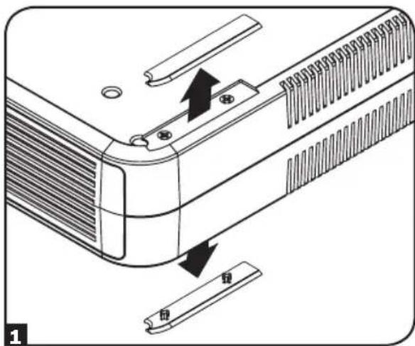
To install the BP24V15RT2U external battery pack in a 2-post rack, remove the mounting hole covers from the top and bottom sides of the pack 1. Attach the mounting ears to each side of the UPS using the included hardware 2. With the help of an assistant, lift the battery pack and attach it to a standard rack with user-supplied hardware 3.
natural_image
Diagram of a device's internal structure showing a component being inserted into a clip, with no visible text or symbols.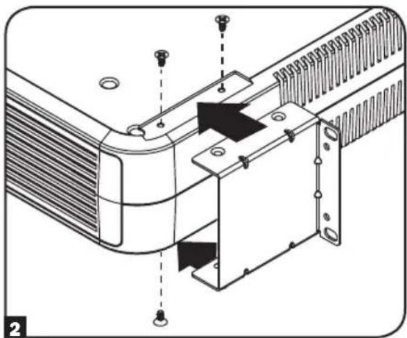
natural_image
Technical diagram of a heat exchanger or cooling unit with mounting holes and internal components (no text or symbols)
text_image
Technical diagram of an air conditioner unit with labeled components and assembly lines
Important: Illustrations show the most common installation configurations; your model may vary. Use only the pre-drilled screw holes to attach mounting brackets to the sides of the battery pack. When installing battery packs into the rack, ensure the weight of the unit is evenly distributed.
Mounting (2-Post Rack or Tower)
Tower Mounting
Select external battery pack models support tower mounting. For increased stability, Tripp Lite recommends the use of the 2-9USTAND (sold separately). Ensure the Battery Orientation Warning label 1 is not facing upward when installing the battery pack in tower orientation. Follow the instructions included with the 2-9USTAND to complete the installation.

text_image
WARNING DO NOT INSTALL PRODUCT WITH THIS LABEL FACING UPBP24V15RT2U Tower Mounting
The BP24V15RT2U will stand in a tower position without the aid of the included hardware. For increased stability, Tripp Lite recommends removing the screw covers from each bottom side 1 and attaching the included hardware 2. In either position, the user must determine the fitness of hardware and procedures before installation.
text_image
回视 回视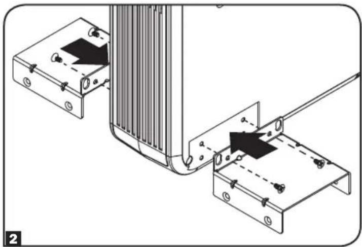
natural_image
Technical diagram showing mechanical assembly with two components and alignment lines (no text or symbols)
NOTICE: If Battery Orientation Warning labels are affixed to both sides of the battery pack, it can only support rack-mount installation.
Connection
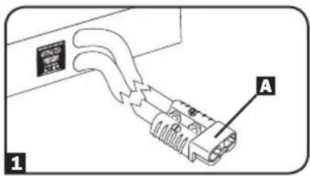
1 Select battery packs have a polarized plug on an output cord permanently connected to the rear panel. Simply plug the output cord directly into the UPS external battery connector (refer to the UPS manual for external battery connector description and location).
Note: Only one of these battery packs is generally connected to a UPS at one time. For longer runtime, use one or more Tripp Lite Battery Packs with daisy-chain capability.
2 Select battery packs feature daisy-chain capability for longer runtime B. To connect multiple battery packs to a single UPS for increased runtime, connect the cabled output connector of the first battery pack to the UPS system's external battery connector, then "daisy-chain" the others: C connect the corded output connector on the second battery pack to the daisy-chain input connector on the second pack, and so on. (Refer to your UPS Owner's Manual for external battery connection description and location.)
text_image
A 1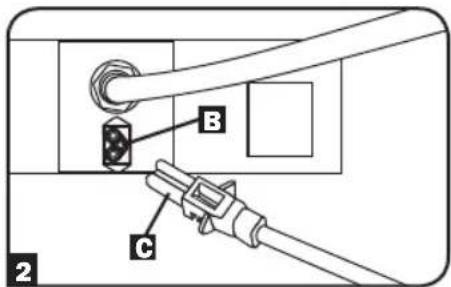
text_image
B C 2Note: Multiple battery pack arrays will provide longer runtimes, but will also require longer recharge times.
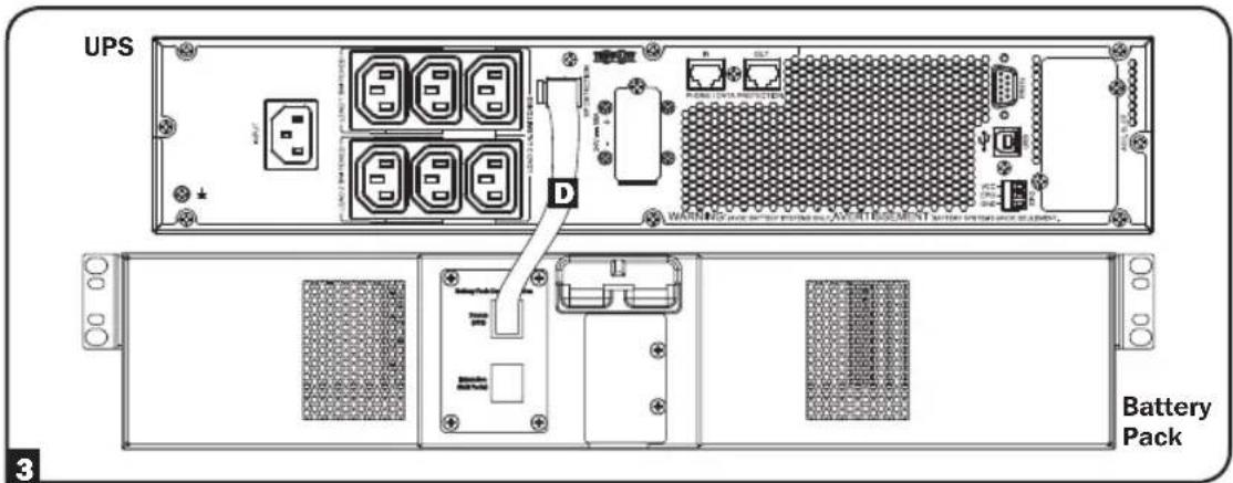
3 Select battery packs contain an external battery detection port on the rear panel. The battery packs should only be used with host UPS models that provide the same functionality. The UPS will automatically detect the external battery upon connection with the battery communication cable D. Check the UPS manual for compatible external battery pack models, configuration requirements and potential limitations. Battery packs are for use only with UPS systems supporting external battery pack detection cabling (this connection is not required if the UPS does not support this feature).
text_image
UPS WARNING: Power & Battery Pack (A) OR TESMENT Battery PackMaintenance
Battery packs require no maintenance but should be kept dry at all times. Avoid installation in locations with high heat and/or humidity. The battery packs should be kept fully charged by being connected to an active UPS system, not left in a depleted condition. Batteries left in a discharged state will suffer a permanent loss of capacity.
Troubleshooting
There is a fuse array inside the battery packs. If a heavy overload or short circuit is encountered, a fuse will open (blow). A battery pack with a blown fuse will deliver no output voltage at any load. A qualified technician must replace the fuses. Contact Tripp Lite Customer Support for additional information.
Storage
Disconnect your battery pack's power cable before storing. If you plan to store your battery pack for an extended period of time, fully recharge its batteries every three months by connecting it to a UPS that is connected to AC input for at least 12 hours.
Service
Your Tripp Lite product is covered by the warranty described in this manual. A variety of Extended Warranty and On-Site Service Programs are also available from Tripp Lite. For more information on service, visit www.tripplite.com/support. Before returning your product for service, follow these steps:
- Review the installation and operation procedures in this manual to insure that the service problem does not originate from a misreading of the instructions.
- If the problem continues, do not contact or return the product to the dealer. Instead, visit www.tripplite.com/support.
- If the problem requires service, visit www.triplite.com/support and click the Product Returns link. From here you can request a Returned Material Authorization (RMA) number, which is required for service. This simple on-line form will ask for your unit's model and serial numbers, along with other general purchaser information. The RMA number, along with shipping instructions will be emailed to you. Any damages (direct, indirect, special or consequential) to the product incurred during shipment to Tripp Lite or an authorized Tripp Lite service center are not covered under warranty. Products shipped to Tripp Lite or an authorized Tripp Lite service center must have transportation charges prepaid. Mark the RMA number on the outside of the package. If the product is within its warranty period, enclose a copy of your sales receipt. Return the product for service using an insured carrier to the address given to you when you request the RMA.
Warranty and Product Registration
2-Year Limited Warranty
Seller warrants this product, if used in accordance with all applicable instructions, to be free from original defects in material and workmanship for a period of 2 years from the date of initial purchase. If the product should prove defective in material or workmanship within that period, Seller will repair or replace the product, at its sole discretion.
THIS WARRANTY DOES NOT APPLY TO NORMAL WEAR OR TO DAMAGE RESULTING FROM ACCIDENT, MISUSE, ABUSE OR NEGLECT. SELLER MAKES NO EXPRESS WARRANTIES OTHER THAN THE WARRANTY EXPRESSLY SET FORTH HEREIN. EXCEPT TO THE EXTENT PROHIBITED BY APPLICABLE LAW, ALL IMPLIED WARRANTIES, INCLUDING ALL WARRANTIES OF MERCHANTABILITY OR FITNESS, ARE LIMITED IN DURATION TO THE WARRANTY PERIOD SET FORTH ABOVE; AND THIS WARRANTY EXPRESSLY EXCLUDES ALL INCIDENTAL AND CONSEQUENTIAL DAMAGES. (Some states do not allow limitations on how long an implied warranty lasts, and some states do not allow the exclusion or limitation of incidental or consequential damages, so the above limitations or exclusions may not apply to you. This warranty gives you specific legal rights, and you may have other rights which vary from jurisdiction to jurisdiction).
WARNING: The individual user should take care to determine prior to use whether this device is suitable, adequate or safe for the use intended. Since individual applications are subject to great variation, the manufacturer makes no representation or warranty as to the suitability or fitness of these devices for any specific application.
Product Registration
Visit www.triplite.com/warranty today to register your new Tripp Lite product. You'll be automatically entered into a drawing for a chance to win a FREE Tripp Lite product!*
* No purchase necessary. Void where prohibited. Some restrictions apply. See website for details.
Tripp Lite has a policy of continuous improvement. Specifications are subject to change without notice.

text_image
TRIPP·LITE
1111 W. 35th Street Chicago, IL 60609 USA • www.tripplite.com/support
text_image
Technical diagram showing two views of a device's internal structure with labeled components and directional arrows indicating assembly or repair.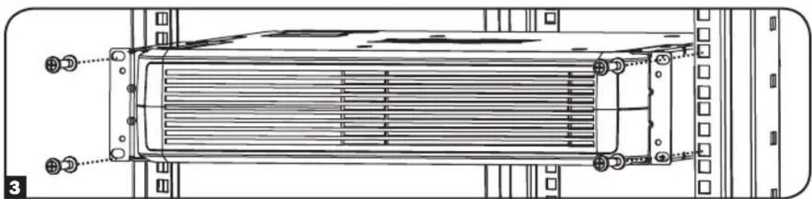
natural_image
Technical line drawing of a heat exchanger or cooling unit with mounting flanges and heat dissipation zones (no text or symbols)Montaje (Rack de 2 Postes o Torre)
text_image
2U 30 2 ↑ X 4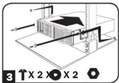
text_image
3 ↑X 2 X̅ X 23U
text_image
1 ↑x 8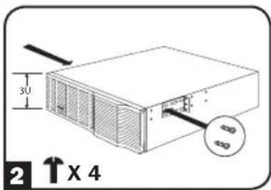
text_image
3U 2 ↑X 4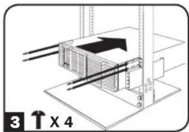
text_image
3 ↑ x 44U

natural_image
Technical diagram of a mechanical assembly with no visible text or symbols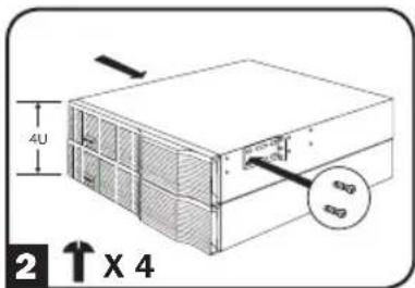
text_image
4U 2 ↑ X 4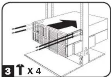
text_image
3 ↑ X 4Montaje (Rack de 2 Postes o Torre)
text_image
Diagram showing a device's internal structure with labeled parts and directional arrows indicating movement or assembly.
natural_image
Technical diagram of a mechanical assembly with mounting holes and internal components (no text or symbols)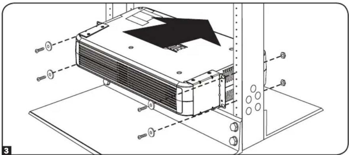
text_image
Technical diagram of a server rack with labeled components and assembly lines
text_image
WARNING DO NOT INSTALL PRODUCT WITH THIS LABEL FACING UP"ADVERTENCIA" NO INSTALE EL PRODUCTO CON ESTA ETIQUETA VIENDO HACIA ARRIBA
natural_image
Technical diagram showing a mechanical assembly with a component and a separate plate, no text or symbols present.
natural_image
Technical diagram showing mechanical assembly with two components and a cable, no visible text or symbols
text_image
4 2U 4 3Utext_image
Technical diagram showing three stages of a heat exchanger or cooling device assembly with labeled components and directional arrows.natural_image
Technical diagram of a mechanical assembly with vertical supports and mounting base (no text or symbols)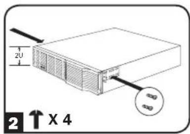
text_image
2U 2 ↑ X 4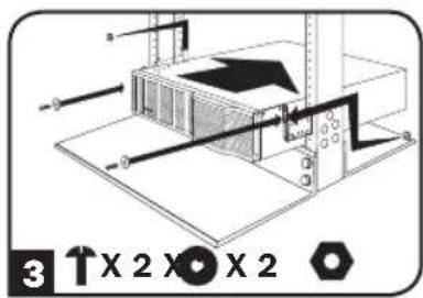
text_image
3 1 X 2 X ⊕ X 23U
natural_image
Technical diagram of a mechanical assembly with vertical supports and mounting base (no text or symbols)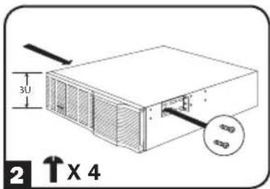
text_image
3U 2 ↑X 4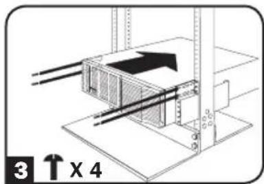
text_image
3 ↑ x 44U
text_image
1 ↑ X 8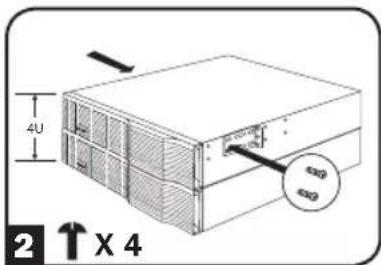
text_image
4U 2 ↑ X 4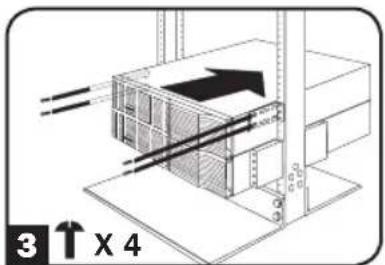
text_image
3 ↑ X 4text_image
Diagram showing a device's internal structure with labeled parts and directional arrows indicating movement or assembly.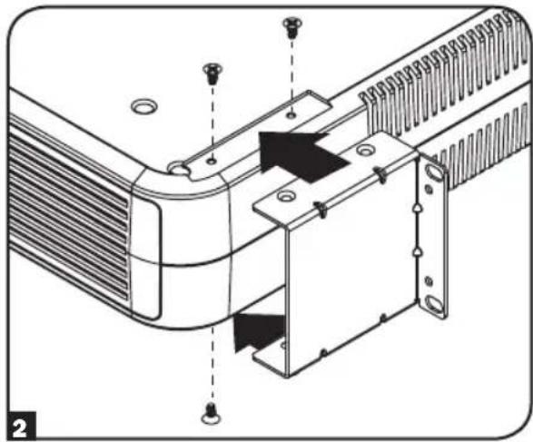
natural_image
Technical diagram of a mechanical assembly with mounting holes and internal components (no text or symbols)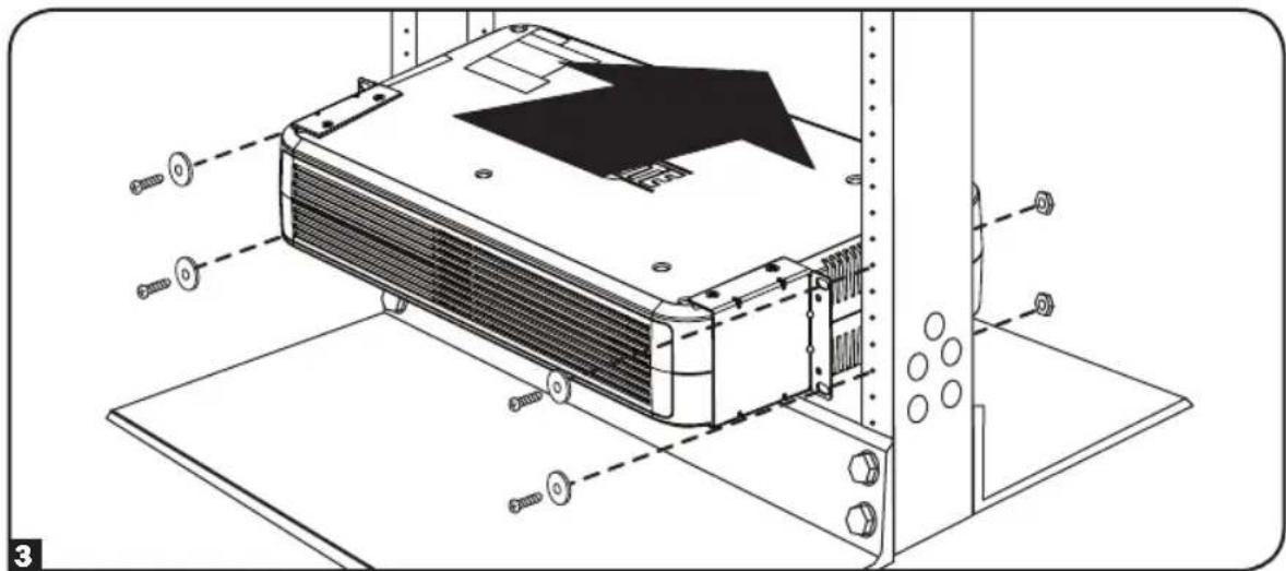
natural_image
Technical line drawing of an air conditioning unit with screws and mounting brackets (no text or symbols)
text_image
WARNING DO NOT INSTALL PRODUCT WITH THIS LABEL FACING UPtext_image
Technical diagram showing a mechanical assembly with labeled parts and directional arrows indicating movement or force.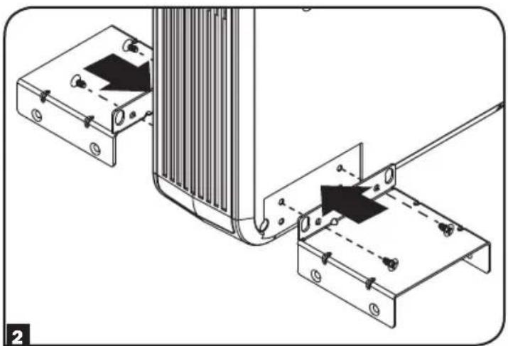
natural_image
Technical diagram showing mechanical assembly with two components and a vertical structure (no text or symbols)
text_image
B C C 2 3Utext_image
Technical diagram showing two views of a device's internal structure with labeled components and directional arrows indicating assembly or repair.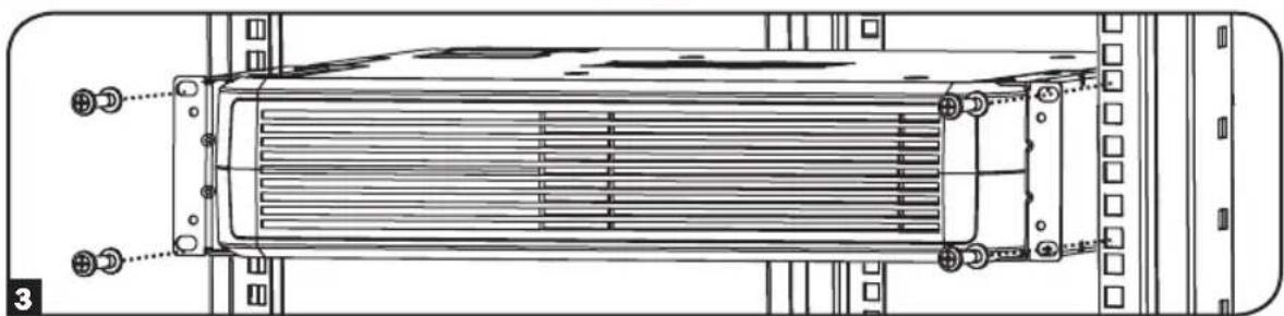
natural_image
Technical line drawing of a heat exchanger or cooling unit with mounting flanges and heat dissipation zones (no text or symbols)text_image
2U 2 ↑ X 4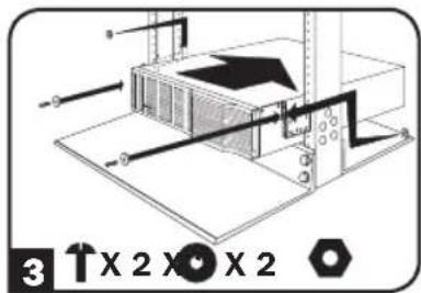
text_image
3 X 2 X 2 X 23U
natural_image
Technical diagram of a mechanical assembly with vertical supports and mounting base (no text or symbols)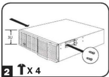
text_image
3U 2 ↑ X 4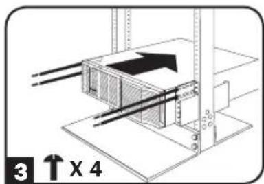
text_image
3 ↑ X 44U
text_image
1 ↑ x 8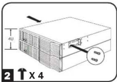
text_image
4U 2 ↑ X 4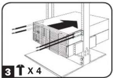
text_image
3 ↑ X 4natural_image
Diagram of a device's internal structure showing a connector and a separate clip (no text or symbols)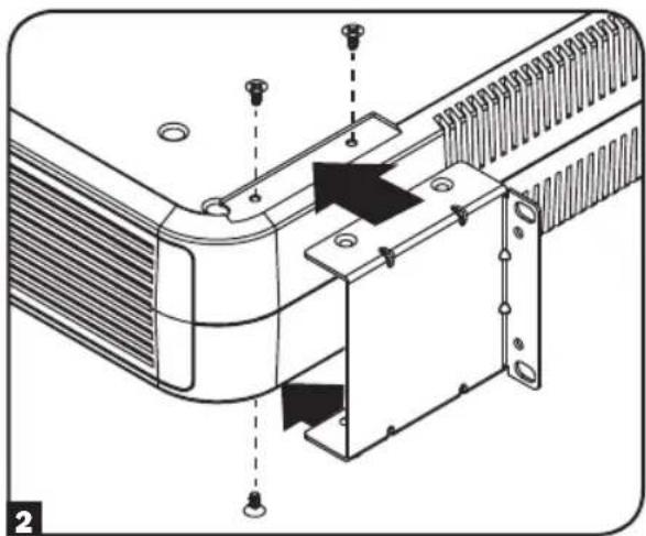
natural_image
Technical diagram of a mechanical assembly with mounting holes and internal components (no text or symbols)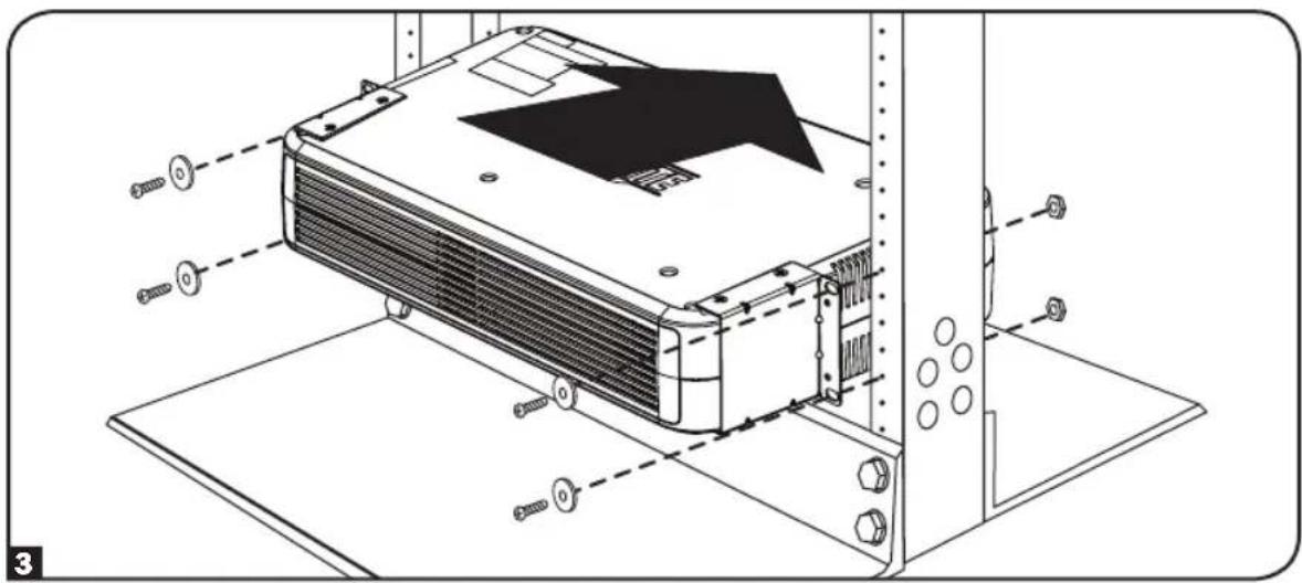
natural_image
Technical line drawing of an air conditioning unit with mounting hardware and screw fasteners (no text or symbols)
text_image
WARNING DO NOT INSTALL PRODUCT WITH THIS LABEL FACING UPnatural_image
Technical diagram showing mechanical assembly with two components and alignment arrows (no text or symbols)