
B127F1A1MMDD - HDMI Extender Tripp Lite - Free user manual and instructions
Find the device manual for free B127F1A1MMDD Tripp Lite in PDF.

| Product Type | DisplayPort Fiber Optic Extension Kit |
| Model | B127F-1A1-MM-DD (Multimode) |
| Maximum Resolution | 4K (3840x2160) at 30 Hz 4:4:4 |
| Maximum Distance | Up to 300 m (1000 ft) with multimode fiber |
| Supported Audio | LPCM, AC-3, DTS 8-channel |
| Compatibility | DisplayPort 1.2a |
| Input | DisplayPort (source) |
| Local Output | 1 DisplayPort port (local monitor) |
| Remote Output | 1 DisplayPort port (remote monitor) |
| Fiber Type | LC duplex multimode 850 nm |
| Fiber Data Rate | 10 Gb |
| Additional Functions | USB 1.1, bidirectional IR, RS-232 (via DIP switch) |
| Plug and Play | Yes, no software or drivers required |
| Mounting | Wall, 19" rack, pole mount (hardware included) |
| Power | External power supply (x2), voltage not specified |
| Dimensions of each unit | Approximately 12 x 8 x 2.5 cm (estimated) |
| Weight of each unit | Approximately 200 g (estimated) |
| Warranty | One-year limited warranty |
| Maintenance and Cleaning | Unplug the device before cleaning. Use a dry, non-abrasive cloth. Do not use liquids or aerosols. |
| Safety | Use only the provided power supplies. Do not expose to water or moisture. Do not open the enclosure. |
| Spare Parts and Repairability | No user-serviceable parts. Contact Tripp Lite technical support for repairs. |
Frequently Asked Questions - B127F1A1MMDD Tripp Lite
User questions about B127F1A1MMDD Tripp Lite
0 question about this device. Answer the ones you know or ask your own.
Ask a new question about this device
Download the instructions for your HDMI Extender in PDF format for free! Find your manual B127F1A1MMDD - Tripp Lite and take your electronic device back in hand. On this page are published all the documents necessary for the use of your device. B127F1A1MMDD by Tripp Lite.
USER MANUAL B127F1A1MMDD Tripp Lite
4K/30 DisplayPort over Fiber Extender Kit
Models:
B127F-1A1-MM-DD
(Multimode),
B127F-1A1-SM-DD
(Singlemode)
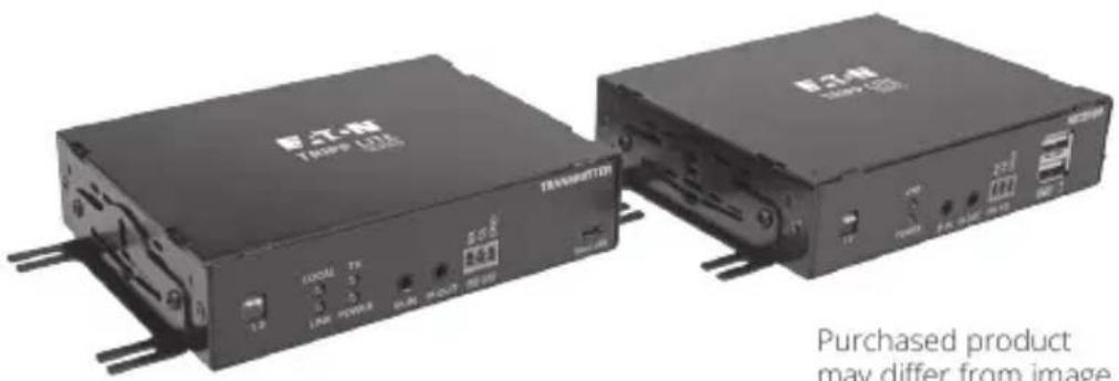
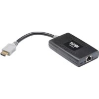
Purchased product may differ from image.
Espanol 11
Français 21
Deutsch 31
Italiano 41
Package Contents
B127F-1A1-MM-DD
(DisplayPort over Duplex LC Multimode Fiber Extender Kit)
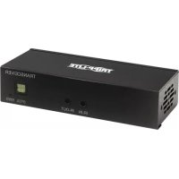
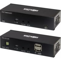
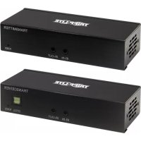
Transmitter Unit
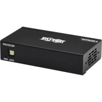
- Receiver Unit
Mounting Hardware
External Power Supply (x2)
B127F-1A1-SM-DD
(DisplayPort over Duplex LC Singlemode Fiber Extender Kit)
Transmitter Unit
- Receiver Unit
Mounting Hardware
External Power Supply (x2)
Product Features
- DisplayPort over Duplex LC Fiber Extender Kits extend a 4K (3840x2160) @ 30 Hz signal:
B127F-1A1-MM-DD - Up to 1000 ft. (305 m) from the source
B127F-1A1-SM-DD - Up to 6.2 mi. (10 km) from the source
Supports 4K (3840x2160) @ 30 Hz 4:4:4 maximum video resolution
Supports 8-channel LPCM, AC-3 and DTS digital audio
- DisplayPort 1.2a compatible
- Plug and play—no software or drivers required
- Additional DisplayPort on the transmitter unit allows connection of a local display, enabling users to monitor the remote display's content
- Remote receiver unit features built-in equalization (EQ) control and auto-EDID image adjustment
2
Product Features
Transmitter and receiver units feature built-in:
B127F-1A1-MM-DD - 10G Multimode LC, 850nm, 300M, DDM transceivers
B127F-1A1-SM-DD - 10G Singlemode LC, 1310nm, 10KM, DDM transceivers
- Local port at transmitter with built-in multi-resolution technology connects any display without affecting 4K/30 Hz signal transmission
- Includes mounting hardware that allows both the local transmitter and remote receiver units to be wall-mounted, rack-mounted or pole-mounted
Optional Accessories
P569-XXX-CERT or P568-XXX-2A Series High-Speed HDMI 2.0 Cable
P580-XXX DisplayPort Cable
N820-Series 10 Gb Duplex Multimode LC-to-LC Fiber Patch Cable
N370-XXM Duplex Singlemode LC-to-LC Fiber Patch Cable
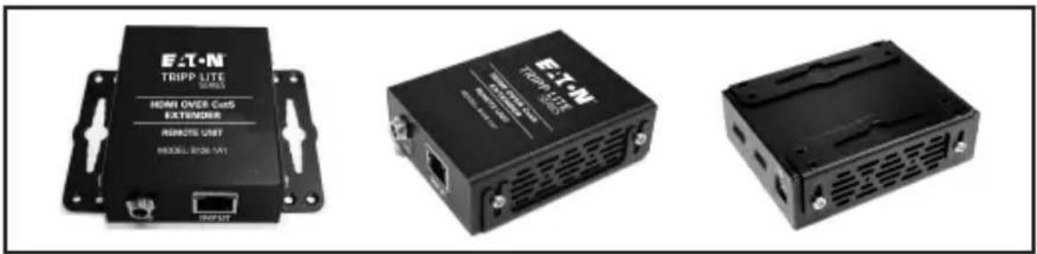
Mounting Instructions
Both extender kit models include mounting hardware that allows for a variety of mounting methods. The following images illustrate how the included mounting brackets can be attached for different installations.
Note: The model shown in the below images is for illustrative purposes only. Your product may vary by model number, size or port orientation. The mounting options for all over IP units are the same.
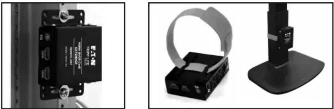
Wall-Mount
19-Inch Rack-Mount Pole-Mount
Standard Extender Kit Installation

Before installation, check the following settings of your source(s) and TV/monitor(s):
- Set the display to 30Hz . Double-check the factory settings, as the default can be set to a lower frequency (Hz) than advertised.
- Verify your monitor has the HDR feature enabled. Some displays may have this feature disabled as a factory setting.
- Check if the Ultra HD (UHD) Deep Color setting is enabled on your TV/monitor. Confirm with your TV/monitor manufacturer which HDMI ports support UHD Deep Color.
Notes:
1) Test to ensure the entire installation works properly before pulling cables through ceilings/walls.
2) To achieve maximum distance and performance, use 10 Gb duplex fiber cabling, such as the N820-Series 10 Gb Duplex Multimode LC-to-LC Fiber Cable (for B127-1A1-MM-DD) or N370-Series Duplex Singlemode LC-to-LC Fiber Cable (for B127-1A1-SM-DD). Preinstalled 10 Gb transceivers are intended to work with 10 Gb fiber cables. Using lower-rated fiber cables can result in signal loss or no image.
Standard Extender Kit Installation
B127F-1A1-XX-DD Extender Kits
B127-1A1-MM-DD: Up to 1000 ft. (300 m) multimode fiber cable
B127-1A1-SM-DD: Up to 2.6 mi. (10 km) singlemode fiber cable
Up to 15 ft. (4.5 m) HDMI 2.0 cable at 4K/30 Hz
Up to 15 ft. (4.5 m) DisplayPort cable at 4K/30 Hz
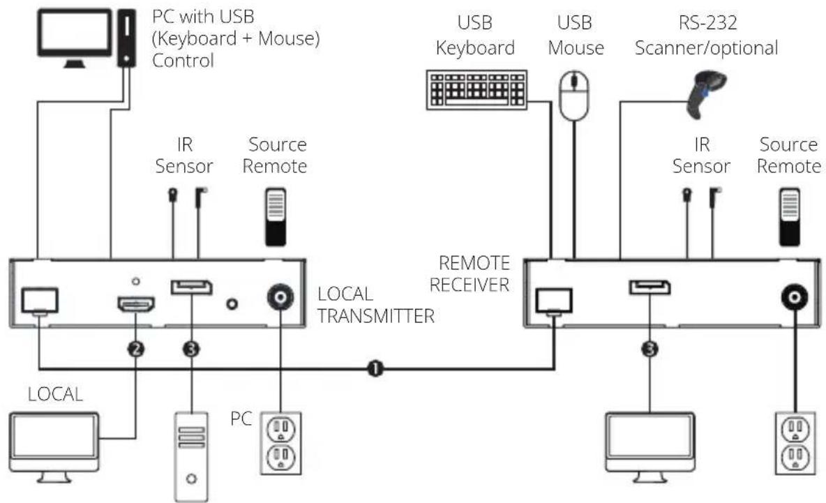
Standard Extender Kit Installation
1 Make sure all equipment in the installation is powered OFF.
Using a DisplayPort cable (such as P580-XXX DisplayPort cables), connect the DisplayPort source to the INPUT port on the local transmitter unit.
(3) (Optional) Using an HDMI 2.0 cable (such as P569-XXX-CERT or P568-XXX-2A Series cables), connect a local monitor to the LOCAL port on the local transmitter unit. The LOCAL (orange) LED will illuminate to indicate the port is connected to a display.
B127F-1A1-MM-DD - Using duplex LC multimode (850 nm) fiber cable (such as the N820-Series cable), connect the LC fiber port on the local transmitter unit to the LC fiber port on the remote receiver unit.
B127F-1A1-SM-DD - Using duplex LC singlemode (1310 nm) fiber cable (such as the N370-XXM Series cable), connect the LC fiber port on the local transmitter unit to the LC fiber port on the remote receiver unit.
Using a DisplayPort cable (such as P580-XXX Series cables), connect the remote receiver unit's DisplayPort to a monitor.
Turn on the power to all of your connected displays (local and remote).
Connect the external power supply to the local transmitter unit and plug it into an available wall outlet or (optional) a Surge Protector, Power Distribution Unit (PDU) or Uninterruptible Power Supply (UPS). The POWER (green) LED on the local transmitter unit will illuminate to indicate the unit is receiving power from the external power supply. The POWER (green) LED on the remote receiver unit will illuminate to indicate the units are receiving power from the external power supply.
Turn on the power to the DisplayPort source. The OUTPUT (orange) LED on the local unit will illuminate to indicate a signal has been received from the source.
The (orange) LED will illuminate on both local transmitter and remote receiver units to indicate a signal has been received from source to display. The screen should now display on the connected monitor.
DIP Switch Settings
Note: This section applies to both B127-1A1-MM-DD and B127-1A1-SM-DD extender kits.
The extender kits provide one of the following functions via DIP switch settings:
- USB 1.1 - One Micro-USB input at transmitter, dual USB-A outputs at receiver
Bi-Directional IR -Dual 3.5 mm jacks at both the transmitter and receiver - RS-232 - One 3-pin phoenix connector at both the transmitter and receiver
| DIP Switch Positions Function Selection | |
| 1 (Up), 2 (Up) IR Function | |
| 1 (Up), 2 (Down) USB Function | |
| 1 (Down), 2 (Down) RS-232 Function | |
(Optional) Connect the computer's DB9 port to the transmitter unit's RS-232 serial port. The serial port is a 3-position phoenix connector for RS-232 (DB connector) pin 2, 3 and 7 connection. Connect your RS-232 device (e.g. barcode scanner) to the 3-position phoenix connector on the receiver unit.
(Optional) Connect the included IR-OUT cable to the transmitter unit's IR-OUT port. Place the sensor on the IR-OUT cable in an unobstructed area within clear view of the device being controlled. Then connect the included IR-IN cable to the receiver unit's IR-IN port. The IR-IN cable will communicate the desired command via the transmitter's IR-OUT cable.
Note: The IR-OUT cable receives the signal from the remote control and sends it to the device being controlled (e.g. Blu-ray™ player, etc.).
(Optional) With a user-supplied USB Micro-B cable (such as the U050-XXX Series USB cable), connect to the transmitter's Micro-B port. Then connect a keyboard and mouse to the available USB-A ports on the receiver unit.
Warranty
1-Year Limited Warranty
We warrant our products to be free from defects in materials and workmanship for a period of one (1) year from the date of initial purchase. Our obligation under this warranty is limited to repairing or replacing (at its sole option) any such defective products. Visit Tripplite.Eaton. com/support/product-returns before sending any equipment back for repair. This warranty does not apply to equipment which has been damaged by accident, negligence or misapplication or has been altered or modified in any way.
EXCEPT AS PROVIDED HEREIN, WE MAKE NO WARRANTYES, EXPRESS OR IMPLIED, INCLUDING WARRANTYES OF MERCHANTABILITY AND FITNESS FOR A PARTICULAR PURPOSE. Some states do not permit limitation or exclusion of implied warranties; therefore, the aforesaid limitation(s) or exclusion(s) may not apply to the purchaser.
EXCEPT AS PROVIDED ABOVE, IN NO EVENT WILL WE BE LIABLE FOR DIRECT, INDIRECT, SPECIAL, INCIDENTAL OR CONSEQUENTIAL DAMAGES ARISING OUT OF THE USE OF THIS PRODUCT, EVEN IF ADVISED OF THE POSSIBILITY OF SUCH DAMAGE. Specifically, we are not liable for any costs, such as lost profits or revenue, loss of equipment, loss of use of equipment, loss of software, loss of data, costs of substitutes, claims by third parties, or otherwise.
Warranty
WEEE Compliance Information for Customers and Recyclers (European Union)
Under the Waste Electrical and Electronic Equipment (WEEE) Directive and implementing regulations, when customers buy new electrical and electronic equipment from Eaton, they are entitled to:
- Send old equipment for recycling on a one-for-one, like-for-like basis (this varies depending on the country)
- Send the new equipment back for recycling when this ultimately becomes waste
Use of this equipment in life support applications where failure of this equipment can reasonably be expected to cause the failure of the life support equipment or to significantly affect its safety or effectiveness is not recommended.
Eaton has a policy of continuous improvement. Specifications are subject to change without notice.
EAT·N
Powering Business Worldwide
Eaton
1000 Eaton Boulevard
Cleveland, OH 44122
United States
Eaton.com
933976
© 2024 Eaton
All Rights Reserved
Publication No. 24-09-161 /
93-3976_RevC
December 2024
Eaton is a registered trademark.
All trademarks are property of their respective owners.
10

Powering Business Worldwide
Eaton
1000 Eaton Boulevard
Cleveland, OH 44122
United States
Eaton.com
© 2024 Eaton
Todoosderechos
reservados
Publication No. 24-09-161 /
93-3976_RevC
Diciembre 2024

933976
Eaton es unamarca registrada.
Powering Business Worldwide
Eaton
1000 Eaton Boulevard
Cleveland, OH 44122
États-Unis
Eaton.com
© 2024 Eaton
Powering Business Worldwide
Eaton
1000 Eaton Boulevard
Cleveland, OH 44122
Vereinigte Staaten
Eaton.com
933976
© 2024 Eaton
Powering Business Worldwide
Eaton
1000 Eaton Boulevard
Cleveland, OH 44122
Stati Uniti
Eaton.com
52
© 2024 Eaton
- 4K/30 DisplayPort over Fiber Extender Kit
- Package Contents
- B127F-1A1-MM-DD
- B127F-1A1-SM-DD
- Product Features
- Optional Accessories
- Mounting Instructions
- Wall-Mount
- 19-Inch Rack-Mount Pole-Mount
- Standard Extender Kit Installation
- Before installation, check the following settings of your source(s) and TV/monitor(s):
- Notes:
- B127F-1A1-XX-DD Extender Kits
- DIP Switch Settings
- Warranty
- 1-Year Limited Warranty
- WEEE Compliance Information for Customers and Recyclers (European Union)
Brand : Tripp Lite
Model : B127F1A1MMDD
Category : HDMI Extender