
B005HUA2K - Switch Tripp Lite - Free user manual and instructions
Find the device manual for free B005HUA2K Tripp Lite in PDF.
| Product Type | 2-Port HDMI KVM Switch |
| Brand | Tripp Lite |
| Model | B005-HUA2-K |
| Maximum Video Resolution | 4K x 2K @ 60 Hz (4K UHD), supports 4:4:4 HDR and HDCP 2.2 |
| HDMI Bandwidth | 18 Gbps |
| KVM Input Connectors | 2 x USB 3.2 Gen 1-B, 2 x HDMI, 2 x 3.5 mm stereo jacks (microphone and audio) |
| Console Connectors | 2 x USB 2.0-A, 1 x HDMI, 2 x 3.5 mm stereo jacks (microphone and audio) |
| USB Hub | 2 USB 3.2 Gen 1-A ports (front) for peripherals |
| Power Supply | External 5 V DC / 3 A, max. consumption 12 W |
| Switching Methods | Front panel buttons, IR remote control, mouse movement, keyboard hotkeys |
| Audio Function | 3.5 mm microphone and stereo speaker jacks (front and rear) |
| System Compatibility | Windows 2000/XP/Vista/7/8/10, Linux, macOS |
| Operating Temperature | 0 ~ 45 °C |
| Operating Humidity | 10% ~ 85% RH (non-condensing) |
| ESD Protection | Contact +/-4 kV, Air +/-8 kV (Human Body Model) |
| Warranty | 3-year limited |
| Package Contents | KVM Switch, USB A/B cables (x2), IR remote, IR extender, power adapter, mounting hardware, manual |
| Care and Cleaning | Disconnect before cleaning. Use a dry, soft cloth. Avoid abrasive or liquid cleaners. |
| Safety | Use only the provided adapter. Do not expose to water or extreme temperatures. |
Frequently Asked Questions - B005HUA2K Tripp Lite
User questions about B005HUA2K Tripp Lite
0 question about this device. Answer the ones you know or ask your own.
Ask a new question about this device
Download the instructions for your Switch in PDF format for free! Find your manual B005HUA2K - Tripp Lite and take your electronic device back in hand. On this page are published all the documents necessary for the use of your device. B005HUA2K by Tripp Lite.
USER MANUAL B005HUA2K Tripp Lite
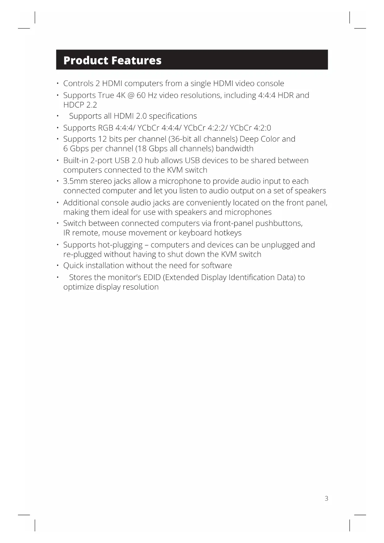
2-Port HDMI KVM Switch
4K Video, Audio and Peripheral Sharing
Model:
B005-HUA2-K
Purchased product may differ from image.
Español 9
Français 17
Deutsch 25
Italiano 37
Package Contents
• B005-HUA2-K 2-Port HDMI KVM Switch
- IR Extender
- IR Remote Control
• (2) USB 3.2 Gen 1 A/B Device Cables (M/M)
- External Power Supply (Input: 100–240V, 50/60 Hz, 0.5A; Output: 5V 3A)
- Mounting Hardware
- Owner's Manual
Optional Accessories
• P785-HKIT06 or P785-HKIT10 KVM Cables
• U322-Series USB 3.2 Gen 1 A/B Device Cables
• P312-Series Mini Stereo Audio Cables
• P568-Series High-Speed HDMI Cables
System Requirements
Console:
- HDMI monitor capable of supporting the highest resolution of any computer in the installation
• USB keyboard and mouse - Microphone and speakers with 3.5 mm stereo connectors (optional)
Computer:
- HDMI input
- USB Type-A port
• 3.5 mm stereo microphone and speaker jacks (optional) - Windows 2000/XP/Vista/Win7/Win8/Win10, Linux or Apple Mac OS operating system
Product Features
• Controls 2 HDMI computers from a single HDMI video console
• Supports True 4K @ 60 Hz video resolutions, including 4:4:4 HDR and HDCP 2.2
• Supports all HDMI 2.0 specifications
• Supports RGB 4:4:4/ YCbCr 4:4:4/ YCbCr 4:2:2/ YCbCr 4:2:0
• Supports 12 bits per channel (36-bit all channels) Deep Color and 6 Gbps per channel (18 Gbps all channels) bandwidth
• Built-in 2-port USB 2.0 hub allows USB devices to be shared between computers connected to the KVM switch
- 3.5mm stereo jacks allow a microphone to provide audio input to each connected computer and let you listen to audio output on a set of speakers
• Additional console audio jacks are conveniently located on the front panel, making them ideal for use with speakers and microphones
- Switch between connected computers via front-panel pushbuttons, IR remote, mouse movement or keyboard hotkeys
- Supports hot-plugging – computers and devices can be unplugged and re-plugged without having to shut down the KVM switch
- Quick installation without the need for software
- Stores the monitor's EDID (Extended Display Identification Data) to optimize display resolution
Panel Descriptions
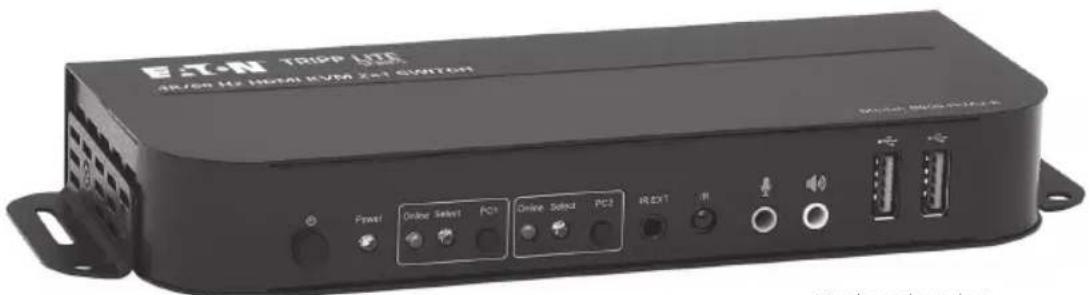
Front Panel
① Power – Press to turn the unit on and off.
② Power Indicator – Illuminates red to signal the DC power supply is connected to an outlet and the KVM switch is turned on.
3 Input Selector – Illuminates blue to indicate whether PC1 or PC2 has been selected. Select LEDs flash in a loop during automatic switching mode. LEDs illuminate when the corresponding USB-B port is connected.
4 IR EXT – Connect the included IR Extender for IR signal reception from the included IR Remote Control.
5 IR – Signal reception point for the IR Remote Control.
6 3.5 mm Microphone – Connect a microphone.
7 3.5 mm Stereo – Connect a stereo audio device.
8 USB-A 3.2 Gen 1 – Connect USB peripherals (printers, scanners, U-disks, etc.).
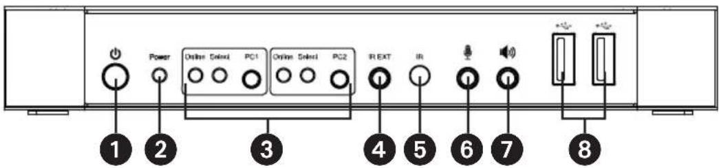
Rear Panel
9 Outputs
a. Connect a mouse and keyboard to the USB 2.0 ports.
b. Connect an amplifier to the 3.5 mm stereo port.
c. Connect a microphone to the 3.5 mm microphone port.
d. Connect a local HDMI monitor to the HDMI Out port.
10 PC 1 Input – Connect to a computer's HDMI, USB, stereo audio and microphone ports.
11 PC 2 Input – Connect to a second computer's HDMI, USB, stereo audio and microphone ports.
⑫ DC 5 V Input – Connect the included 5V/3A DC power supply.
Installation and Operation
Refer to the following steps and diagram to set up your KVM switch installation.
Note: Before making any connections, make sure power to all devices connected to the KVM switch is turned off. Unplug the power cords of any computers that have the Keyboard Power On function.

flowchart
graph TD
    A["User Interface"] --> B["USB Devices (Printer, Scanner, U-disk, etc)"]
    A --> C["Power Supply"]
    A --> D["PC1 PC2"]
    A --> E["Amplifier"]
    A --> F["HDMI Display"]
    A --> G["Desktop Computer"]
    A --> H["Mouse"]
    A --> I["Keyboard"]
    A --> J["Mic"]
    A --> K["IR Extender"]
- Connect computers to the USB-B input ports using USB cables. Connect the computers' microphone and stereo audio ports using 3.5 mm audio cables. Connect computers to the "HDMI In" ports using HDMI cables.
- Connect a keyboard and mouse to the USB-A ports on the rear panel. Connect a microphone and amplifier to the microphone and stereo audio ports using 3.5 mm audio cables. Connect a monitor to "HDMI Out" using a HDMI cable.
- Connect the included DC power supply, and press the Power button. The Power LED will illuminate. When computers are connected to the PC1 and PC2 ports, the Online LEDs will illuminate.
Installation and Operation
- Press the buttons on the front panel to select the desired computer. The Select LED will illuminate to indicate which computer is currently selected. The monitor will show the corresponding image, and the selected computer can be controlled via keyboard and mouse.
- The included IR Remote Control works the same as the pushbuttons:
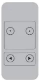
natural_image
Simple diagram with four numbered circles and two play buttons, no text or symbols presenta. For input: "1" specifies PC1 and "2" specifies PC2.
b. For loop switching: Order is PC1>PC2>PC1>...
- USB peripherals, such as printers, scanners and thumb drives, can be connected to the front-panel USB-A ports.
Special Function Operation
- Mouse Traversal Function – Place the mouse on the far right of the monitor, and continue to slide it to the right for 2 seconds. The KVM switch will automatically switch to the next port. Switching order is PC1>PC2>PC1>...
- USB-B Detection Switching Function:
a. When the unit detects that a computer is connected to the USB-B port, the unit immediately switches to that computer, and the corresponding Online and Select LEDs illuminate. For instance, if PC1 is already connected, then PC2 becomes connected via USB-B, and the KVM will automatically switch to PC2.
b. When the currently selected computer is powered off or the USB cable is dialed out, the KVM automatically switches to the next computer with the power on and the USB port connected.
Special Function Operation
3. Hotkey Function:
| Number | Hotkey Combination Function Description | |
| 1 | [Scroll Lock]++ ^1 [Scroll Lock] + → or ↓ | Switch to the next port |
| 2 | [Scroll Lock]++ [Scroll Lock] + ← or ↑ | Switch to the previous port |
| 3 | [Scroll Lock]++ [Scroll Lock] + [X] ^2 | Switch to PC "X" |
| 4 | [Scroll Lock]++ [Scroll Lock] + [S] ^3 | Enable Automatic Switching (Default: 15 seconds) |
| 5 | [Scroll Lock]++ [Scroll Lock] + [I] + [N] ^4 + [Enter] | Set the Automatic Switching Interval (Between 5 ~ 999 seconds) |
| 6 | [Scroll Lock]++ [Scroll Lock] + [B] + [1/0] ^5 | Buzzer On/Off (Default: On) |
| 7 | [Scroll Lock]++ [Scroll Lock] + [F] + [L] + [A] + [S] + [H] + [Enter] | All resume hotkey default mode ^6 |
Notes:
- Hotkeys are not case-sensitive.
- A noise sounds when switching between PC1 and PC2.
1 “++” means to press [Scroll Lock] twice in rapid succession. For example: [Scroll Lock] ++ [Scroll Lock] + [1]" means to press the Scroll Lock button twice in rapid succession and then press the number 1 button. The detection period between each hotkey code is 5 seconds. If the Scroll Lock button is pressed the first time and 5 seconds pass before the Scroll Lock button is pressed again, the hotkey code will be invalid.
^2 “X” indicates the PC input. For example, to switch to PC2, the hotkey combination is [Scroll Lock]++ [Scroll Lock] + [2].
^3 Turning on this function will cause HDMI, microphone and speaker ports to enter automatic switching mode without USB. Press any key (except Spacebar) to exit to the port used prior to the automatic switching sequence. Press Spacebar to stay at the port currently in use. When automatic switching mode is enabled, the corresponding "Select" LED of the port currently in use will flash.
^4 “N” indicates the number of switching interval, which can be 5 seconds to 999 seconds.
5 "1" means On, "0" means Off.
^6 This mode only relates to hotkey function #4 and #6.
Specifications
| Connectors | |
| KVM Connectors (Female) USB 3.2 | Gen 1-B x2 (Rear)HDMI x2 (Rear)3.5 mm Stereo Jack x2 (Green, Rear)3.5 mm Stereo Jack x2 (Pink, Rear) |
| Console Connectors (Female) USB | 2.0-A x2 (Rear)HDMI x1 (Rear)3.5 mm Stereo Jack x2 (Green, 1 Front, 1 Rear)3.5 mm Stereo Jack x2 (Pink, 1 Front, 1 Rear) |
| USB Hub Connectors (Female) USB | 3.2 Gen 1-A x2 (Front) |
| Video Resolution | |
| Maximum Resolution 4K x 2K @ 60 | Hz (4K UHD) |
Specifications
| Operating Bandwidth | |
| HDMI Bandwidth 18 Gb | |
| Environmental | |
| Operating Temperature Range 32° | ~ 113°F (0° ~ 45°C) |
| Operating Humidity Range 10% ~ 8 | 5% RH (No Condensation) |
| Storage Temperature Range 14° ~ | 176°F (-10° ~ 80°C) |
| Storage Humidity Range 5% ~ 90% | RH (No Condensation) |
| Power Requirement | |
| External Power Supply DC 5V/3A | |
| Power Consumption (Max) 12W | |
| ESD Protection | |
| Human Body Model +/- 8kV (Air Gap Discharge)+/- 4kV (Contact Discharge) | |
Warranty
3-YEAR LIMITED WARRANTY
We warrant our products to be free from defects in materials and workmanship for a period of three (3) years from the date of initial purchase. Our obligation under this warranty is limited to repairing or replacing (at its sole option) any such defective products. Visit Tripplite.Eaton.com/support/product-returns before sending any equipment back for repair. This warranty does not apply to equipment which has been damaged by accident, negligence or misapplication or has been altered or modified in any way.
EXCEPT AS PROVIDED HEREIN, WE MAKE NO WARRANTIES, EXPRESS OR IMPLIED, INCLUDING WARRANTIES OF MERCHANTABILITY AND FITNESS FOR A PARTICULAR PURPOSE. Some states do not permit limitation or exclusion of implied warranties; therefore, the aforesaid limitation(s) or exclusion(s) may not apply to the purchaser.
EXCEPT AS PROVIDED ABOVE, IN NO EVENT WILL WE BE LIABLE FOR DIRECT, INDIRECT, SPECIAL, INCIDENTAL OR CONSEQUENTIAL DAMAGES ARISING OUT OF THE USE OF THIS PRODUCT, EVEN IF ADVISED OF THE POSSIBILITY OF SUCH DAMAGE. Specifically, we are not liable for any costs, such as lost profits or revenue, loss of equipment, loss of use of equipment, loss of software, loss of data, costs of substitutes, claims by third parties, or otherwise.
Eaton has a policy of continuous improvement. Specifications are subject to change without notice. Photos and illustrations may differ slightly from actual products.
natural_image
Simple diagram of a remote control panel with four buttons (one left, one right, one left, one right) and two directional arrows (left and right), no text or symbols present.a. Para entrada: "1" especifica PC1 y "2" especifica PC2.
natural_image
Simple diagram of a mobile phone control panel with four buttons (one left, one right, one left, one right) and a play button, no text or symbols present.natural_image
Simple diagram with four circular icons labeled 1, 2, and two play buttons below (no text or symbols beyond icons)- 2-Port HDMI KVM Switch
- 4K Video, Audio and Peripheral Sharing
- Package Contents
- Optional Accessories
- System Requirements
- Console:
- Computer:
- Product Features
- Panel Descriptions
- Front Panel
- Rear Panel
- Installation and Operation
- Special Function Operation
- Hotkey Function:
- Notes:
- Specifications
- Warranty
- 3-YEAR LIMITED WARRANTY
Brand : Tripp Lite
Model : B005HUA2K
Category : Switch