
B3204X1MH - Hi-fi system Tripp Lite - Free user manual and instructions
Find the device manual for free B3204X1MH Tripp Lite in PDF.
| Product Type | 4-Port Multi-Format Presentation Switch |
| Brand | Tripp Lite |
| Model | B3204X1MH (B320-4X1-MH) |
| Number of Input Ports | 4 |
| Input Port Types | HDMI, DisplayPort, VGA + 3.5mm audio, USB-C (x2) |
| Output Port | HDMI |
| Maximum HDMI Resolution | 4096 x 2160 @ 60 Hz with 4:4:4 |
| Maximum DisplayPort/USB-C Resolution | 4096 x 2160 @ 60 Hz with 4:4:4 |
| Maximum VGA Resolution | 1920 x 1080 @ 60 Hz |
| Power Supply (AC Adapter) | Input: 100-240 V AC, Output: 24 V DC 1 A |
| USB-C PD Charging Power | Up to 90 W (100 W input, 10 W reserved for chipset) |
| Switching Methods | Front push buttons, IR remote, RS-232 commands |
| Remote Control | IR with included receiver cable |
| RS-232 Control | DB9 port, 57,600 baud rate |
| Button Lock | Yes (simultaneous press of Input 1 and Input 2 for 5 seconds) |
| Operating Temperature | 0 to 40 °C (32 to 104 °F) |
| Storage Temperature | -15 to 50 °C (5 to 122 °F) |
| Warranty | 1 year (limited) |
| Package Contents | Switch, IR remote + cable, AC adapter, 4 plug adapters, mounting hardware, manual |
Frequently Asked Questions - B3204X1MH Tripp Lite
User questions about B3204X1MH Tripp Lite
0 question about this device. Answer the ones you know or ask your own.
Ask a new question about this device
Download the instructions for your Hi-fi system in PDF format for free! Find your manual B3204X1MH - Tripp Lite and take your electronic device back in hand. On this page are published all the documents necessary for the use of your device. B3204X1MH by Tripp Lite.
USER MANUAL B3204X1MH Tripp Lite
4-Port Presentation Switch
Model: B320-4X1-HH-K1, B320-4X1-HH-K2, B320-4X1-MH, B320-4X1-MHB-K, B320-4X1-MHE-K
Español 19 • Français 37 • Русский 55
WARRANTY REGISTRATION
Register your product today and be automatically entered to win an ISOBAR ^® surge protector in our monthly drawing!
tripplite.com/warranty


Manufacturing Excellence.
1111 W. 35th Street, Chicago, IL 60609 USA • tripplite.com/support
Copyright © 2020 Tripp Lite. All rights reserved.
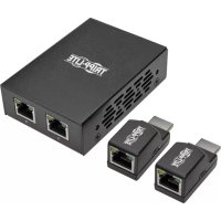
Package Contents
• B320-4X1-Series Presentation Switch
- IR Remote Control
- IR Receiver Cable, 5 ft.
• International Power Supply (Input: 100–240V; Output: 24V 1A)
• (x4) International Plug Adapters (North America, U.K., Europe, Australia)
- Mounting Hardware
- Owner's Manual
Optional Accessories
• N202-Series Cat6 24 AWG Solid-Wire Patch Cables
• P569-XXX-CERT Series High-Speed HDMI 2.0 Cables
• P580-Series DisplayPort Cables with Latches
• P502-XXX-SM 15-Pin Low-Profile VGA Coaxial Cables
• U420-Series USB-C 3.1 Gen 1/2 Cables
• P312-Series 3.5 mm Audio Cables
Product Features
B320-4X1-HH-K1
4-Port 4K @ 60 Hz HDMI over Cat6 PoC Presentation Switch/Extender Kit, 50 ft.
- Connects up to 4 HDMI sources to a single HDMI display up to 50 ft. away via Cat6 cabling.
- Switches between 4 sources using the front-panel pushbuttons, IR remote control or RS-232 commands.
- Power over Cable (PoC) technology provides power to the receiver via Cat6 cable.
- Remote receiver unit features built-in equalization (EQ) control and auto EDID image adjustment.
- Supports true 4K resolutions up to 3840 x 2160 @ 60 Hz with 4:4:4 chroma subsampling.
• HDMI 2.0 and HDCP 2.2 compliant. - Plug-and-play operation with no software required for easy, immediate installation.
B320-4X1-HH-K2
4-Port 4K @ 60 Hz HDMI over Cat6 PoC Presentation Switch/Extender Kit, 125 ft.
- Connects up to 4 HDMI sources to a single HDMI display up to 125 ft. away via Cat6 cabling.
- Switches between 4 sources using the front-panel pushbuttons, IR remote control or RS-232 commands.
- Power over Cable (PoC) technology provides power to the receiver via Cat6 cable.
- Remote receiver unit features built-in equalization (EQ) control and auto EDID image adjustment.
- Supports true 4K resolutions up to 3840 x 2160 @ 60 Hz with 4:4:4 chroma subsampling.
• HDMI 2.0 and HDCP 2.2 compliant. - Plug-and-play operation with no software required for easy, immediate installation.
Product Features
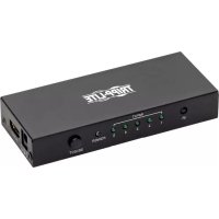
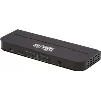
B320-4X1-MH
4-Port Multi-Format Presentation Switch
- Connects up to 4 sources to a single HDMI display.
- Switches between 4 sources using the front-panel pushbuttons, IR remote control or RS-232 commands.
- Supports true 4K HDMI, DisplayPort and USB-C™ resolutions up to 4096 x 2160 @ 60 Hz with 4:4:4 chroma subsampling.
• Supports 1080p VGA resolutions up to 1920 x 1080 @ 60 Hz. - USB-C PD 3.0 port supports up to 100W (20V 5A) and provides 90W of charging power to the USB-C source.*
- Plug-and-play operation with no software required for easy, immediate installation.
*10W is reserved for the functionality of the USB Type-C™ chipset system.
B320-4X1-MHB-K
4-Port Multi-Format PoC Presentation Switch/Extender Kit, 50 ft.
- Connects up to 4 sources to a single HDMI display up to 50 ft. away via Cat6 cabling.
- Switches between 4 sources using the front-panel pushbuttons, IR remote control or RS-232 commands.
- Power over Cable (PoC) technology provides power to the receiver via Cat6 cable.
- Remote receiver unit features built-in equalization (EQ) control and auto EDID image adjustment.
- Supports true 4K HDMI, DisplayPort and USB-C resolutions up to 3840 x 2160 @ 60 Hz with 4:4:4 chroma subsampling.
• Supports 1080p VGA resolutions up to 1920 x 1080 @ 60 Hz. - USB-C PD 3.0 port supports up to 100W (20V 5A) and provides 90W of charging power to the USB-C source.*
- Plug-and-play operation with no software required for easy, immediate installation.
*10W is reserved for the functionality of the USB Type-C chipset system.
Product Features
B320-4X1-MHE-K
4-Port Multi-Format PoC Presentation Switch/Extender Kit, 125 ft.
- Connects up to 4 sources to a single HDMI display up to 125 ft. away via Cat6 cabling.
- Switches between 4 sources using the front-panel pushbuttons, IR remote control or RS-232 commands.
- Power over Cable (PoC) technology provides power to the receiver via Cat6 cable.
- Remote receiver unit features built-in equalization (EQ) control and auto EDID image adjustment.
- Supports true 4K HDMI, DisplayPort and USB-C resolutions up to 3840 x 2160 @ 60 Hz with 4:4:4 chroma subsampling.
• Supports 1080p VGA resolutions up to 1920 x 1080 @ 60 Hz. - USB-C PD 3.0 port supports up to 100W (20V 5A) and provides 90W of charging power to the USB-C source.*
- Plug-and-play operation with no software required for easy, immediate installation.
*10W is reserved for the functionality of the USB Type-C chipset system.
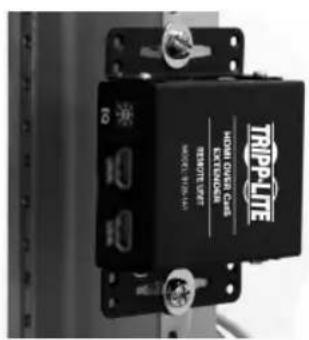
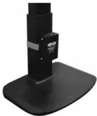
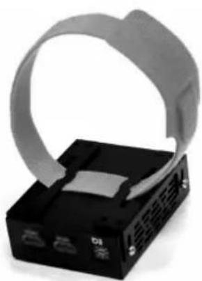
Mounting Instructions
These 4-port presentation switches include hardware for mounting on a wall, pole or 19-inch rack. The following images illustrate how the included hardware can be attached for different installations.
Note: The models shown below are for illustrative purposes only. Your product may vary by model number, size or port orientation. The mounting options for all B320-Series switches are the same.
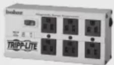
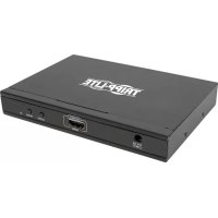
Wall-mount

natural_image
Black plastic electronic device casing with ventilation slots and mounting holes (no visible text or symbols)19" Rack-mount
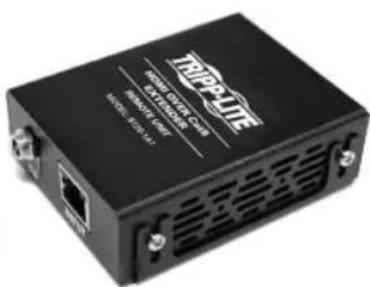
Pole-mount
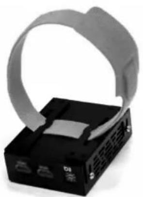
natural_image
Close-up of a black electronic device with a gray cable strap and ventilation slots (no visible text or symbols)
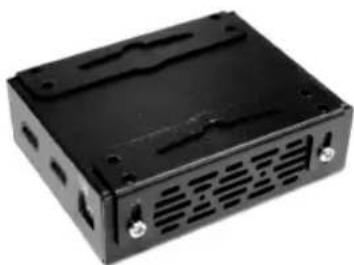
natural_image
Close-up of a black mechanical stand with a vertical support and base (no visible text or symbols)Installation
Refer to the following steps and diagram to set up your 4-port presentation switch installation.
Installation Instructions for B320-4X1-HH-K1 & B320-4X1-HH-K2
Notes:
- Test to ensure the entire installation works properly before pulling cables through ceilings/walls.
- To achieve maximum distance and performance, use 24 AWG solid-wire Cat6 cables. Using stranded-wire Cat6 cable or cable with a gauge (AWG) size higher than 24 AWG will result in shorter extension distance. Higher-gauge cabling, such as 26 AWG, has more limited transmission capability than lower-gauge cabling. All Tripp Lite N202-Series Cat6 cables are made with 24 AWG solid-wire cabling.
- External power is not required for remote receiver units, due to PoC technology incorporated in the transmitter units.
Installation
- Make sure all equipment in the installation is powered off.
- Connect the HDMI source to INPUT 1 on the presentation switch with a user-supplied HDMI cable.
- Repeat Step 2 for INPUT ports 2, 3 and 4.
- Connect the RJ45 port on the presentation switch to the RJ45 port on the remote receiver with a user-supplied Cat6 cable. Note: Maximum transmission distance via Cat6 cabling for the B320-4X1-HH-K1 and B320-4X1-HH-K2 is 50 ft. and 125 ft., respectively.
- Connect the remote receiver's HDMI port to a display with a user-supplied HDMI cable.
- (Optional) If the B320-4X1-Series switch is not in line of sight, connect the included IR receiver cable to the IR-IN port for more reliable IR reception.
- (Optional) If you wish to control the B320-4X1-Series switch from your computer, connect a user-supplied DB9 cable to the RS-232 port. See RS-232 Commands for more information.
- Turn on the power to all connected devices in the installation. Then, connect the included external power supply to the switch transmitter unit.
- The Power LED will illuminate green, indicating the unit is receiving sufficient power, and Input LEDs will illuminate orange, indicating a signal is being received from the sources.
Installation
Installation Instructions for B320-4X1-MH, B320-4X1-MHB-K & B320-4X1-MHE-K
Notes:
- Test to ensure the entire installation works properly before pulling cables through ceilings/walls.
- To achieve maximum distance and performance, use 24 AWG solid-wire Cat6 cables. Using stranded-wire Cat6 cable or cable with a gauge (AWG) size higher than 24 AWG will result in shorter extension distance. Higher-gauge cabling, such as 26 AWG, has more limited transmission capability than lower-gauge cabling. All Tripp Lite N202-Series Cat6 cables are made with 24 AWG solid-wire cabling.
- External power is not required for remote receiver units due to PoC technology incorporated in the transmitter units.
B320-4X1-MH switch
① Up to 15 ft. (4.5 m) HDMI 2.0 cable at 4K/60Hz
② Up to 15 ft. (4.5 m) DisplayPort cable at 4K/60Hz
③ Up to 15 ft. (4.5 m) VGA cable at 1080p/60Hz
④ Up to 6 ft. (1.83 m) USB Type-C cable at 4K/60Hz
⑤ Up to 30 ft. (9 m) HDMI 2.0 cable at 4K/60Hz
⑥ RS-232 cable
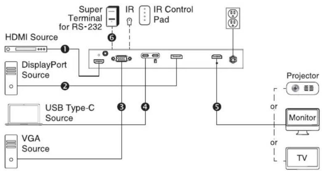
flowchart
graph TD
    A["HDMI Source"] -->|1| B["DisplayPort Source"]
    B -->|2| C["USB Type-C Source"]
    C -->|3| D["Camera"]
    C -->|4| E["Monitor"]
    C -->|5| F["TV"]
    B --> G["Super Terminal for RS-232"]
    G --> H["IR"]
    H --> I["IR Control Pad"]
    I --> J["Projector"]
    style A fill:#f9f,stroke:#333
    style B fill:#ccf,stroke:#333
    style C fill:#cfc,stroke:#333
    style D fill:#fcc,stroke:#333
    style E fill:#cff,stroke:#333
    style F fill:#ffc,stroke:#333
    style G fill:#fff,stroke:#333
    style H fill:#fff,stroke:#333
    style I fill:#fff,stroke:#333
    style J fill:#fff,stroke:#333
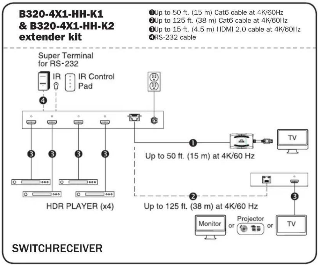
Installation
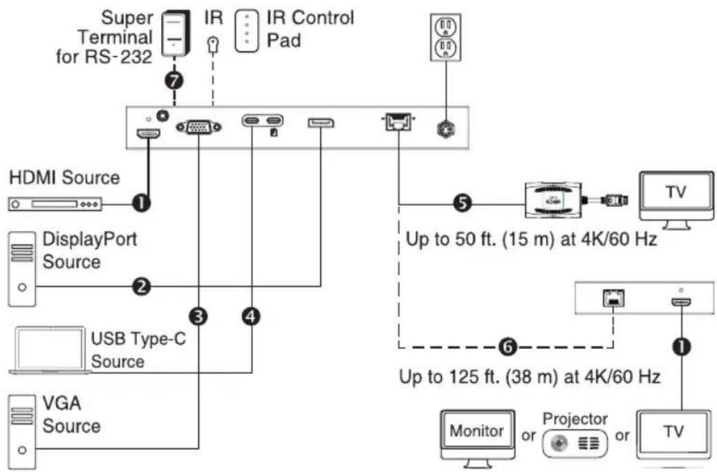
B320-4X1-MHB-K & B320-4X1-MHE-K extender kit
① Up to 15 ft. (4.5 m) HDMI 2.0 cable at 4K/60Hz
② Up to 15 ft. (4.5 m) DisplayPort cable at 4K/60Hz
③ Up to 15 ft. (4.5 m) VGA cable at 1080p/60Hz
④ Up to 6 ft. (1.83 m) USB Type-C cable at 4K/60Hz
⑤ Up to 50 ft. (15 m) Cat6 cable at 4K/60Hz
⑥ Up to 125 ft. (38 m) Cat6 cable at 4K/60Hz
⑦ RS-232 cable
flowchart
graph TD
    A["Super Terminal for RS-232"] -->|7| B["IR"]
    B --> C["IR Control Pad"]
    D["HDMI Source"] -->|1| E["+"]
    F["DisplayPort Source"] -->|2| G["+"]
    H["USB Type-C Source"] -->|3| I["+"]
    J["VGA Source"] -->|4| K["+"]
    L["Monitor or Projector or TV"] -->|5| M["+"]
    N["TV"] -->|6| O["+"]
    P["Up to 50 ft. (15 m) at 4K/60 Hz"] --> M
    Q["Up to 125 ft. (38 m) at 4K/60 Hz"] --> O
SWITCHRECEIVER
- Make sure all equipment in the installation is powered off.
- Connect the HDMI source to HDMI IN with a user-supplied HDMI cable.
- Connect the DisplayPort source to DP IN with a user-supplied DisplayPort cable.
- Connect the USB-C source to TYPE-C IN with a user-supplied USB-C cable.
- (Optional) Connect your USB-C source's power adapter to CHARGE IN, supporting up to 100W (20V 5A) and supplying up to 90W of power to your USB-C source.
- Connect the VGA source to VGA IN with a user-supplied VGA cable. Then connect the VGA source's Audio Out port to VGA AUDIO with a user-supplied 3.5 mm audio cable. Note: 15-pin VGA cables must be used. 14-pin VGA cables will not work.
Installation
- Connect the HDMI Output port to a display with a user-supplied HDMI cable.
- B320-4X1-MHB-K & B320-4X1-MHE-K only: Connect the RJ45 port on the switch transmitter to the RJ45 port on the remote receiver with a user-supplied Cat6 cable. Note: Maximum transmission distance via Cat6 cabling for the B320-4X1-MHB-K and B320-4X1-MHE-K is 50 ft. and 125 ft., respectively. Then, connect the remote receiver's HDMI port to a display with a user-supplied HDMI cable.
- (Optional) If the B320-4X1-Series switch is not in line of sight, connect the included IR receiver cable to IR-IN for more reliable IR reception.
- (Optional) If you wish to control the B320-4X1-Series switch from your computer, connect a user-supplied DB9 cable to the RS-232 port. See RS-232 Commands for more information.
- Turn on the power to all connected devices in the installation. Then, connect the included external power supply to the switch transmitter unit.
- The Power LED will illuminate green, indicating the unit is receiving sufficient power, and Input LEDs will illuminate orange, indicating a signal is being received from the sources.
Locking Front-Panel Pushbuttons
Users can lock the front-panel pushbuttons to prevent accidental changes or button clicks. To lock the front-panel pushbuttons:
- Press Input 1 and 2 simultaneously and hold for 5 seconds.
- All four Input LEDs (1-4) will blink for 5 seconds, then only the selected source LED will turn orange.
- Front-panel pushbuttons are now inoperable.
To unlock the front-panel pushbuttons:
- Press Input 1 and 2 simultaneously and hold for 5 seconds.
- All four Input LEDs (1-4) will blink for 5 seconds, then only the selected source LED will turn orange.
- Front-panel pushbuttons are now operable again.
Installation
RS-232 Serial Control Installation
- Please make sure your Terminal Emulator Software is running.
- Set up your serial COM port. Open your software, click Setup and select Serial Port from the dropdown menu.
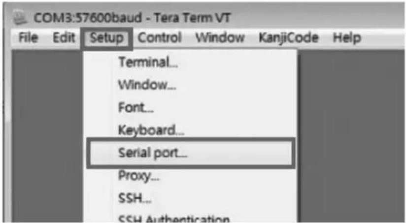
-
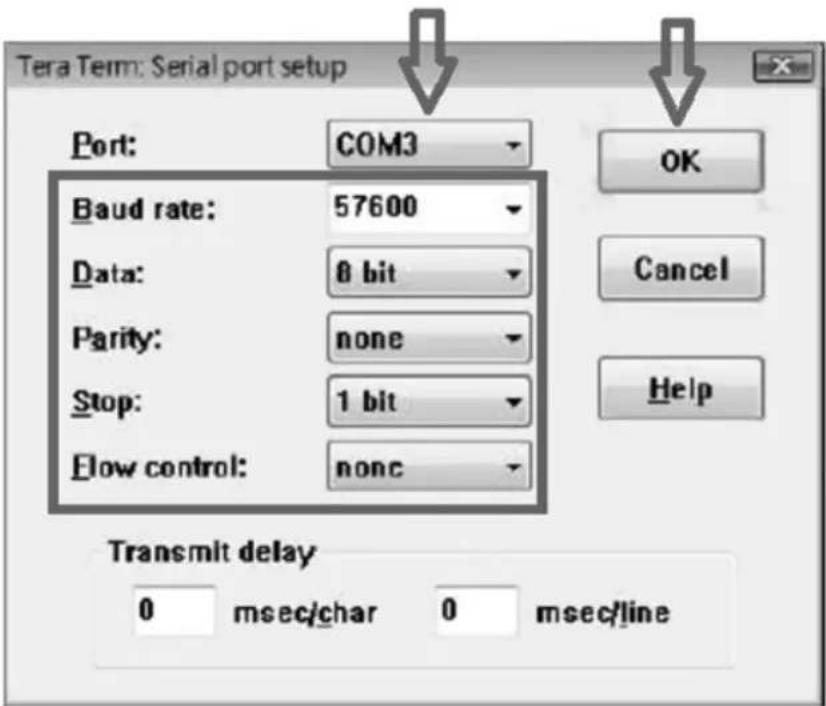
Select the COM port into which the DB9 is connected. If you use Keyspan ^® , it will automatically assign the COM port for you. Please make sure to select:
-
Baud Rate: 57600
- Data: 8 bit
- Parity: none
- Stop: 1 bit
- Flow control: None and click OK.
Installation
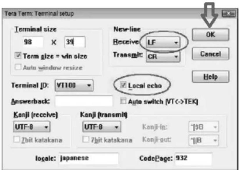
- Configure your software to allow input control. Click Setup and select Terminal from the dropdown menu.
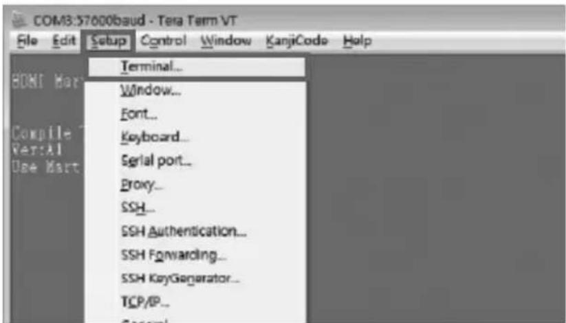
- Select LF on Receive in New-Line. Click the box to activate Local Echo. Enter the command and click OK.
Installation
RS-232 Commands
| Commands for Serial Control | |
| Command Meaning | |
| Sw1 x1 Routed to Output1, Output n to input [x1] | |
| Sw2 x1 Routed to Output1, Output n to input [x1] | |
| Sw3 x1 Routed to Output1, Output n to input [x1] | |
| Sw4 x1 Routed to Output1, Output n to input [x1] | |
| PWD Stands for Power On/Off | |
| STE State of the output | |
Important note control command:
Only one command can be issued at a time. You must wait for the switch to accept and finish the first command before sending a second. If a second command is sent/issued before the first is completed, the switch will ignore the second command.
Installation
Routing Functions
Command:
- swN M
Variations:
• N: stands for Connect Output N, default 1
• M: switch to input M
Response:
- CMD: swN M
Response Example:
- sw1 a
- CMD: sw1 A
Output 1, Select Input A
- sw2 b
- CMD: sw2 B
Output 2, Select Input B
Power Functions
Command: pwd
Response: PW
Stands for Power On/Off
- pwd
- CMD: PWD
Special Commands
Command: ste
Response: OutputN M[STATE]
Variations:
• N: Output N
• M: Input M
• [STATE]:
o [Signal] signal on from input
o [Idle] no signal from input
State of the output channel
• STE
- CMD: STATE
- Output1 A[Idle]
- Output2 A[Idle]
Specifications
| Models B320-4X1-HH-K1 B320-4X1-HH-K2 B320-4X1-MH B320-4X1-MHB-K B320-4X1-MHE-K | |||||
| Input Ports (Female) | 4x HDMI 4x HDMI HDMI, DP, VGA + | 3.5mm, 2x USB-C | HDMI, DP, VGA + 3.5mm, 2x USB-C | HDMI, DP, VGA + 3.5mm, 2x USB-C | |
| Output Ports (Female) | RJ45 RJ45 HDMI RJ45 RJ45 | ||||
| RX Max Distance | 50 ft. 125 ft. N/A 50 ft. | 125 ft. | |||
| Max Resolution | HDMI: 3840 x 2160 @ 60 Hz | HDMI: 3840 x 2160 @ 60 Hz | HDMI/DP/USB-C: 4096 x 2160 @ 60 Hz; VGA: 1920 x 1080 @ 60 Hz | HDMI/DP/USB-C: 3840 x 2160 @ 60 Hz; VGA: 1920 x 1080 @ 60 Hz | HDMI/DP/USB-C: 3840 x 2160 @ 60 Hz; VGA: 1920 x 1080 @ 60 Hz |
| Operating Temp | 32 to 104°F | 32 to 104°F | 32 to 104°F | 32 to 104°F | 32 to 104°F |
| Storage Temp | 5 to 122°F | 5 to 122°F | 5 to 122°F | 5 to 122°F | 5 to 122°F |
| PD 3.0 Charging | N/A | N/A | 20V 5A (100W) | 20V 5A (100W) | 20V 5A (100W) |
Warranty and Product Registration
1-Year Limited Warranty
Seller warrants this product, if used in accordance with all applicable instructions, to be free from original defects in material and workmanship for a period of one (1) year from the date of initial purchase. If the product should prove defective in material or workmanship within that period, Seller will repair or replace the product, at its sole discretion.
THIS WARRANTY DOES NOT APPLY TO NORMAL WEAR OR TO DAMAGE RESULTING FROM ACCIDENT, MISUSE, ABUSE OR NEGLECT. SELLER MAKES NO EXPRESS WARRANTIES OTHER THAN THE WARRANTY EXPRESSLY SET FORTH HEREIN. EXCEPT TO THE EXTENT PROHIBITED BY APPLICABLE LAW, ALL IMPLIED WARRANTIES, INCLUDING ALL WARRANTIES OF MERCHANTABILITY OR FITNESS, ARE LIMITED IN DURATION TO THE WARRANTY PERIOD SET FORTH ABOVE; AND THIS WARRANTY EXPRESSLY EXCLUDES ALL INCIDENTAL AND CONSEQUENTIAL DAMAGES. (Some states do not allow limitations on how long an implied warranty lasts, and some states do not allow the exclusion or limitation of incidental or consequential damages, so the above limitations or exclusions may not apply to you. This warranty gives you specific legal rights, and you may have other rights which vary from jurisdiction to jurisdiction.)
Some states do not permit limitation or exclusion of implied warranties; therefore, the aforesaid limitation(s) or exclusion(s) may not apply to the purchaser.
WARNING: The individual user should take care to determine prior to use whether this device is suitable, adequate or safe for the use intended. Since individual applications are subject to great variation, the manufacturer makes no representation or warranty as to the suitability or fitness of these devices for any specific application.
Product Registration
Visit tripplite.com/warranty today to register your new Tripp Lite product. You'll be automatically entered into a drawing for a chance to win a FREE Tripp Lite product!*
*No purchase necessary. Void where prohibited. Some restrictions apply. See website for details.
Warranty and Product Registration
WEEE Compliance Information for Tripp Lite Customers and Recyclers (European Union)
Under the Waste Electrical and Electronic Equipment (WEEE) Directive and implementing regulations, when customers buy new electrical and electronic equipment from Tripp Lite they are entitled to:
- Send old equipment for recycling on a one-for-one, like-for-like basis (this varies depending on the country)
- Send the new equipment back for recycling when this ultimately becomes waste
Use of this equipment in life support applications where failure of this equipment can reasonably be expected to cause the failure of the life support equipment or to significantly affect its safety or effectiveness is not recommended.


1111 W. 35th Street, Chicago, IL 60609 USA • tripplite.com/support
20-05-025 93-3CA4_RevA
1111 W. 35th Street, Chicago, IL 60609, EE UU • tripplite.com/support
natural_image
Black plastic electronic device casing with ventilation slots and mounting holes (no visible text or symbols)natural_image
Black electronic device with a gray cable strap and ventilation slots (no visible text or symbols)natural_image
Close-up of a black mechanical stand with a flat base and vertical support (no visible text or symbols)Instalación
Instalación
Instalación
Comandos de RS-232
| Comandos para Control Serial | |
| Comando Significado | |
| Sw1 x1 Enrutado a Output1, Salida N a entrada [x1] | |
| Sw2 x1 Enrutado a Output1, Salida N a entrada [x1] | |
| Sw3 x1 Enrutado a Output1, Salida N a entrada [x1] | |
| Sw4 x1 Enrutado a Output1, Salida N a entrada [x1] | |
| PWD Apoyo para Encendido y Apagado | |
| STE Estado de la salida | |
Importante tome nota del comando de control:
1111 W. 35th Street, Chicago, IL 60609, EE UU • tripplite.com/support
20-05-025 93-3CA4_RevA
1111 W. 35th Street, Chicago, IL 60609 USA • tripplite.com/support
natural_image
Black plastic electronic device casing with ventilation slots and mounting holes (no visible text or symbols)natural_image
Close-up of a black electronic device with a gray ribbon strap and two ports (no visible text or symbols)Montage sur poteau
natural_image
Close-up of a black industrial support base with a vertical cylindrical component and a flat base (no visible text or symbols)Installation
Installation
Installation
Commandes RS-232
1111 W. 35th Street, Chicago, IL 60609 USA • tripplite.com/support
20-05-025 93-3CA4_RevA
1111 W. 35th Street, Chicago, IL 60609 USA • tripplite.com/support
natural_image
Black plastic electronic device casing with ventilation slots and mounting holes (no visible text or symbols)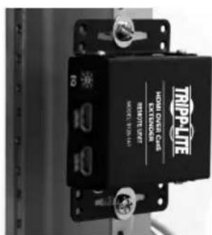
natural_image
Close-up of a black electronic device with a gray circular component attached, no visible text or symbols.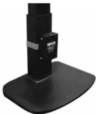
natural_image
Close-up of a black industrial stand with a base, no visible text or symbolsУстановка
Установка
Установка
1111 W. 35th Street, Chicago, IL 60609 USA • tripplite.com/support
20-05-025 93-3CA4_RevA
- 4-Port Presentation Switch
- WARRANTY REGISTRATION
- Package Contents
- Optional Accessories
- Product Features
- B320-4X1-HH-K1
- B320-4X1-HH-K2
- B320-4X1-MH
- B320-4X1-MHB-K
- B320-4X1-MHE-K
- Mounting Instructions
- Installation
- Installation Instructions for B320-4X1-HH-K1 & B320-4X1-HH-K2
- Notes:
- Installation Instructions for B320-4X1-MH, B320-4X1-MHB-K & B320-4X1-MHE-K
- B320-4X1-MH switch
- B320-4X1-MHB-K & B320-4X1-MHE-K extender kit
- SWITCHRECEIVER
- Locking Front-Panel Pushbuttons
- RS-232 Serial Control Installation
- Important note control command:
- Routing Functions
- Power Functions
- Special Commands
- Warranty and Product Registration
- 1-Year Limited Warranty
- Product Registration
- WEEE Compliance Information for Tripp Lite Customers and Recyclers (European Union)
- Instalación
- Importante tome nota del comando de control:
- Установка
Brand : Tripp Lite
Model : B3204X1MH
Category : Hi-fi system