SmartRack SRCOOL18K - Air Conditioning Tripp Lite - Free user manual and instructions
Find the device manual for free SmartRack SRCOOL18K Tripp Lite in PDF.
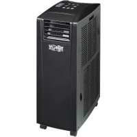
| Product Type | Self-contained portable air conditioner |
| Brand | Tripp Lite |
| Model | SmartRack SRCOOL18K |
| Cooling Capacity | 18,000 BTU/h |
| Refrigerant | R410A (environmentally friendly) |
| Power Supply | 208/240V, 60Hz, 15A |
| Dimensions (approx.) | 74.9 x 54.6 x 102.9 cm (29.5 x 21.5 x 40.5 in) |
| Weight (approx.) | 56.7 kg (125 lbs) |
| Operating Modes | Cool, Dehumidify, Fan with High/Medium/Low/Auto speeds, Silent Mode, On/Off timer |
| Cold Air Outlet | Louvered vent (pre-installed) or flexible cooling duct (optional) |
| Hot Air Exhaust | Two flexible exhaust ducts (max 300 cm) with adjustable panels for window or drop ceiling |
| Evaporation Function | Auto-evaporative: condensate is re-evaporated into the hot air stream, eliminating the need for manual draining (except in dehumidify mode or high humidity) |
| Air Filters | Front condenser filter (2 x 30.5 x 45.7 x 2.5 cm) and rear evaporator filter (2 x 35.6 x 45.7 x 2.5 cm); replaceable |
| Display and Controls | Digital temperature display, buttons for power, function, temperature, fan speed, timer, silent mode |
| Automatic Restart | Yes, after a power outage, the unit resumes with the last settings |
| Safety | Automatic shutdown if water tank is full (code E4), anti-frost protection (code dF), 3-minute compressor delay |
| Warranty | 1 year limited |
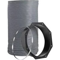
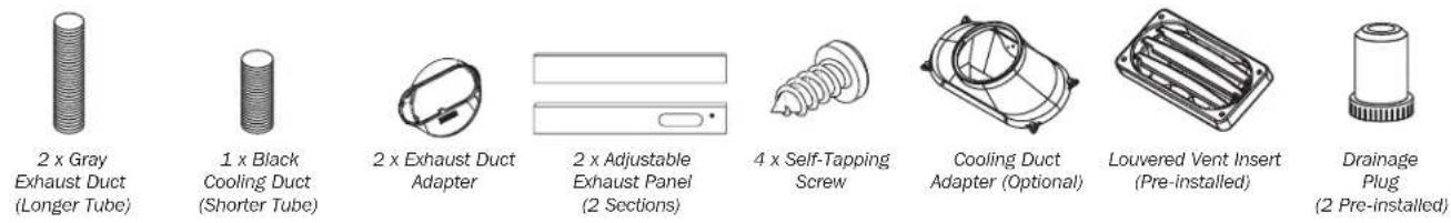
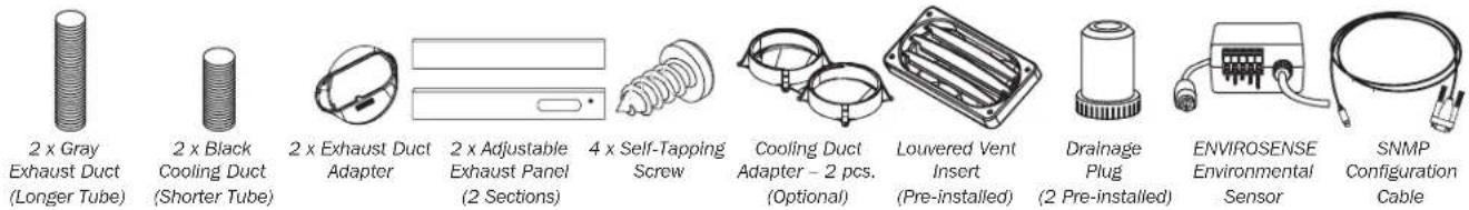
| Included Accessories | 2 gray exhaust ducts, 1 black cooling duct, 2 exhaust adapters, 2 adjustable exhaust panels, screws, drain plugs |
| Routine Maintenance | Clean filters every 2 weeks; replace worn filters; clean cabinet with a dry, non-abrasive cloth |
Frequently Asked Questions - SmartRack SRCOOL18K Tripp Lite
User questions about SmartRack SRCOOL18K Tripp Lite
0 question about this device. Answer the ones you know or ask your own.
Ask a new question about this device
Download the instructions for your Air Conditioning in PDF format for free! Find your manual SmartRack SRCOOL18K - Tripp Lite and take your electronic device back in hand. On this page are published all the documents necessary for the use of your device. SmartRack SRCOOL18K by Tripp Lite.
USER MANUAL SmartRack SRCOOL18K Tripp Lite
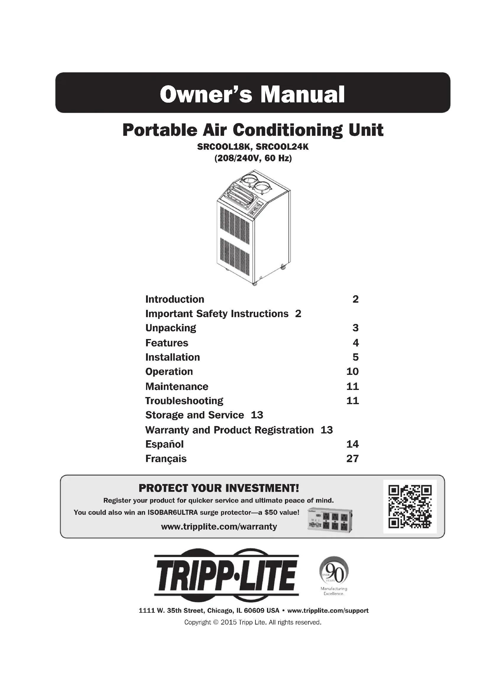
Portable Air Conditioning Unit
SRCOOL18K, SRCOOL24K (208/240V, 60 Hz)
natural_image
Line drawing of a dual-chamber air conditioning unit with cooling fans and control panel (no text or symbols)Introduction 2
Important Safety Instructions 2
Unpacking 3
Features 4
Installation 5
Operation 10
Maintenance 11
Troubleshooting 11
Storage and Service 13
Warranty and Product Registration 13
Español 14
Français 27
PROTECT YOUR INVESTMENT!
Register your product for quicker service and ultimate peace of mind.
You could also win an ISOBAR6ULTRA surge protector—a \$50 value!
www.tripplite.com/warranty


1111 W. 35th Street, Chicago, IL 60609 USA • www.tripplite.com/support
Copyright © 2015 Tripp Lite. All rights reserved.
Introduction
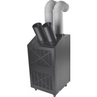
The self-contained Portable Air Conditioning Unit provides 18,000 or 24,000 BTUs of supplemental cooling capacity. Designed for IT environments, it's ideal for cooling overheated rack enclosures, IT equipment hot spots and network closets without access to facility air conditioning. The Portable Air Conditioning Unit can focus cool air through its flexible cooling duct or cool a small room through its louvered vent. The SRCOOL24K's cooling output feature allows cool air to be split between two racks. It also filters and dehumidifies air to improve operating conditions and equipment reliability. Condensate is re-evaporated for drip-free operation, so you won't waste time emptying water collection tanks. The self-contained design does not require any plumbing or special circuits, so setup is quick and easy. Eco-friendly R410A refrigerant meets environmental standards worldwide.
Recommended Applications:
natural_image
Line drawing of a server rack unit with ventilation fans and control panel (no text or symbols)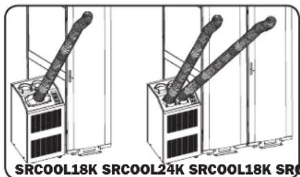
natural_image
Technical line drawing of two server rack units with diagonal connectors, no text or symbols present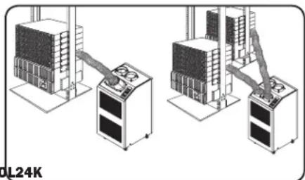
natural_image
Illustration of industrial equipment with control panels and a rack-mounted unit (no visible text or symbols)- Cooling a small room. 2. Cooling an overheated rack enclosure. 3. Cooling an equipment hot spot inside or
outside a rack enclosure.
Important Safety Instructions
SAVE THESE INSTRUCTIONS
This manual contains instructions and warnings that should be followed during the installation, operation and storage of this product. Failure to heed these warnings may affect your warranty.
Warnings
- The individual user should determine prior to use whether this device is suitable, adequate or safe for the use intended. Since individual applications are subject to great variation, the manufacturer makes no representation or warranty as to the suitability or fitness of this device for any specific application.
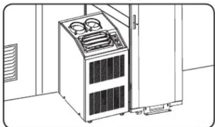
• Install the unit indoors, away from extreme temperatures or humidity, direct sunlight, dust and conductive contaminants. - Leave adequate space around the unit for ventilation, with rear and vented sides not less than 20 inches (51 cm) from walls or other obstacles.
• Install the unit on a flat surface with a gradient no more than 10^ . - Connect the unit directly to a grounded AC power outlet. Failure to do so may cause an electric shock or fire.
- This unit is designed to supply supplemental cooling for localized hot spots. It is not intended for continuous use.
- The power supply for the unit must be rated in accordance with the unit's nameplate.
- Do not modify the plug nor use an adapter that would eliminate the ground connection.
- Do not use an extension cord to connect the unit to an AC outlet. Use only the power cord that came with the unit.
- Comply with all applicable wiring and safety regulations, such as National Electrical Code (NEC) in the United States.
- Do not plug additional equipment into the outlet where the unit is plugged in. Overloading the outlet may cause an electric shock or fire.
- Do not attempt to turn the unit on or off by connecting or disconnecting the AC plug. A serious electric shock may occur. Use the ON/OFF button to turn the unit on or off.
- Turn the unit off and unplug it from the AC outlet before performing maintenance.
- Before connecting the unit to a dedicated drainage system, turn it off and unplug it. There is a risk of electric shock while the unit is plugged in.
- Maintenance should be performed by trained personnel only.
- Do not use thinners, alcohol, detergents or abrasive brushes to clean the unit's cabinet. These items may damage the cabinet.
- Do not pour water over the unit. This may cause an electric shock and damage the unit.
- Do not operate the unit without the air filter. This may cause dust accumulation that may damage the unit.
- Do not attempt to operate the unit in a room with inadequate air circulation. Provide makeup air in accordance with applicable building codes.
- Do not place objects on top of the unit.
- Use of this equipment in life support applications where failure of this equipment can reasonably be expected to cause the failure of the life support equipment or to significantly affect its safety or effectiveness is not recommended. Do not use this equipment in the presence of a flammable anesthetic mixture with air, oxygen or nitrous oxide.
Unpacking
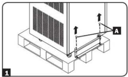
Note: Make sure the unit and attached pallet is placed on a level surface before unpacking.
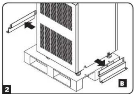
1 After removing the protective covering, wrapping, foam insulation and other packing materials (instructions found in the Unpacking Instructions guide attached to the outside of the unit), remove the four bolts A securing the unit to the pallet with an appropriately sized wrench.
2 Remove the two shipping brackets by pulling the top lip under and away from the unit B.
3 Position at least one person on each side of the unit and slowly push it toward the back of the shipping pallet c until all four casters go over the edge of the pallet and touch the floor. WARNING: Use at least one assistant when removing the unit from the pallet.
natural_image
Technical diagram of a server rack with mounting bracket and control panel (no text or symbols)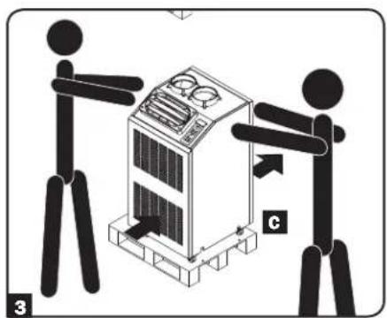
Features
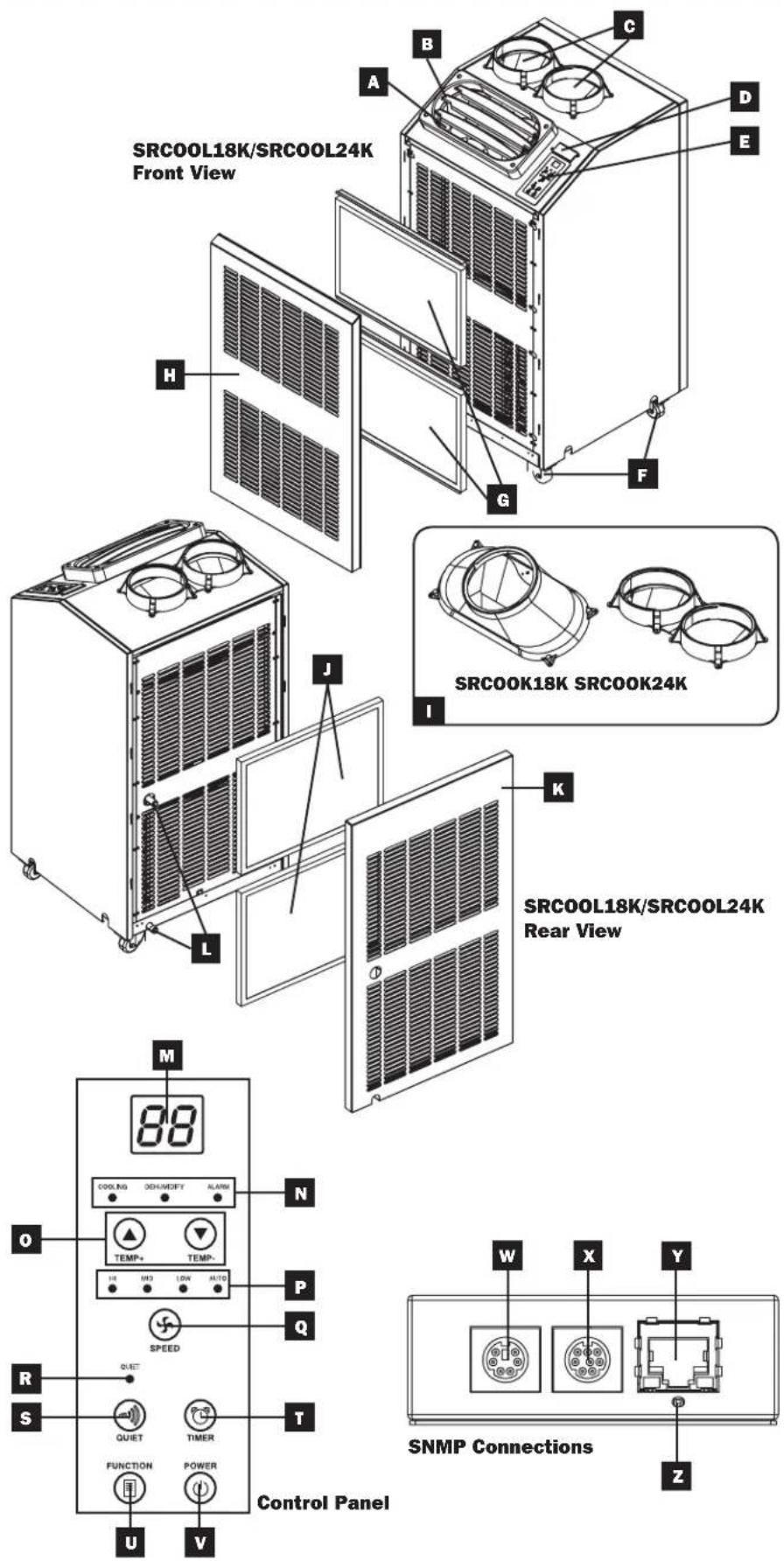
SRCOOL18K/SRCOOL24K
A Cool Air Output
B Louvered Vent Insert (Pre-Installed)
C Warm Air Exhaust
D SNMP Accessory Slot*
* SNMP card pre-installed with SRCOOL24K model
E Control Panel
F Casters
G Condenser Filters
(Included – see Maintenance section for filter replacement)
H Front Panel
1 Cooling Duct Adapter (Optional, Varies by Model)
J Evaporator Filters
(Included – see Maintenance section for filter replacement)
K Rear Panel
Evaporator Drainage Outlets
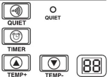
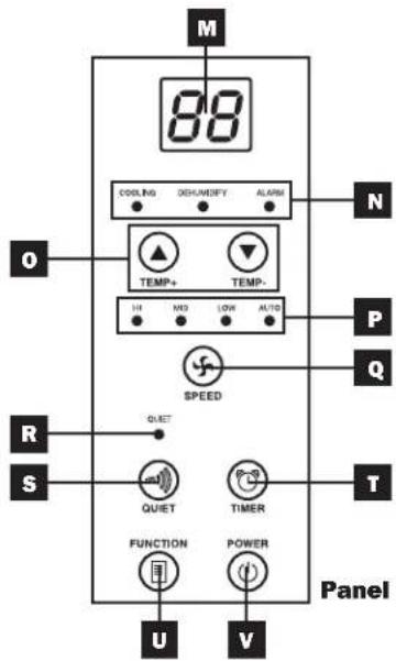
Control Panel
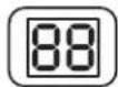
M Numeric Display
N Operating Mode LEDs
o Temperature Control Buttons
P Fan Speed Mode LEDs
Q "FAN SPEED" Button
R "QUIET" LED
S "QUIET" Button
"TIMER" Button
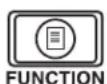
"FUNCTION" Button
"POWER" Button
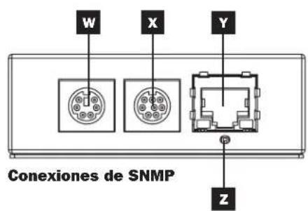
SNMP Connections
(SRCOOL24K Only)
W PS/2 Port (for use with ENVIROSENSE accessory – included with SRCOOL24K)
X Mini-DIN Serial Port
Y RJ45 Ethernet Network Port
SNMP Reset Button
Note: Use a pin, paper clip, or point tool to access the recessed reset button. Do not use excessive force when engaging the reset button.
Installation
Warning: After removing the unit from the shipping container, check for damage or missing parts (refer to the parts list below). If you notice a problem, visit www.tripplite.com/support for service. Do not attempt to operate a damaged unit.
Accessory Parts List:
SRCOOL18K
SRCOOL24K
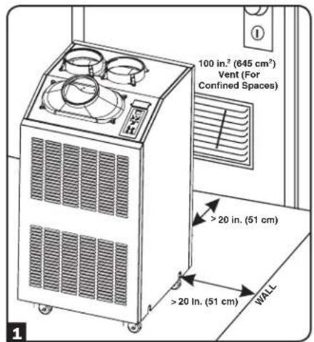
1 Unit Placement
Place the unit on a flat, level surface near a grounded AC outlet rated in accordance with the unit nameplate (90-110% of specified voltage). Leave adequate space around the unit for ventilation, with the front and rear not less than 20 inches (51 cm) from walls or other obstacles. Place the unit in a location with convenient access to a drop ceiling or window to provide the straightest, shortest path available for the flexible exhaust duct. If you plan to use the flexible cooling duct to focus cool air on a specific rack enclosure or device, place the unit near the targeted rack enclosure or device to provide the straightest, shortest path available for the cooling duct.
Warning: Do not use an extension cord to connect the unit to an AC outlet. Use only the power cord that came with the unit.
Note: If the unit will operate in a confined space (such as closet), you must supply makeup air in order to maintain airflow efficiency. A 100 in. ^2 (645 cm ^2 ) or larger vent installed near the bottom of the door should supply adequate makeup air for a typical closet. Consult applicable building codes for more information.
Exhaust hose not shown—see Section 3.
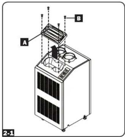
2 Cooling Duct Connection (Optional)
The pre-installed louvered vent insert is appropriate for room cooling applications. If you plan to cool a room, skip step 2 and proceed to step 3. If you plan to use the flexible cooling duct to focus cool air on a specific device or rack enclosure, follow the instructions below.
2-1 Remove the louvered vent insert A by removing the screws B using a Phillips screwdriver and lifting the vent from the unit.
Note: The SRCOOL24K's cooling duct connection allows cool air to be split between two racks.
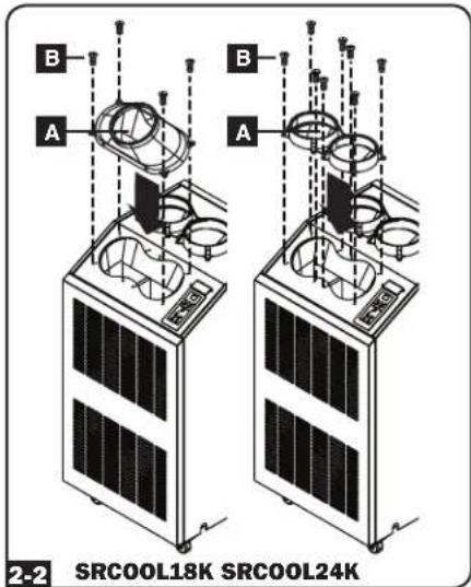
Installation (continued)
2-2 Align the cooling duct adapter with the cool air output A. Using a Phillips screwdriver, secure it to the unit with the screws used for securing the pre-installed louvered vent B.
Note: The SRCOOL24K cooling duct adapter requires four additional screws (included).
2-3 Connect the flexible black cooling duct tube A to the cooling duct adapter B. Align the duct with the circular adapter opening, push the duct downward and turn the duct clockwise until it screws into the adapter solidly.
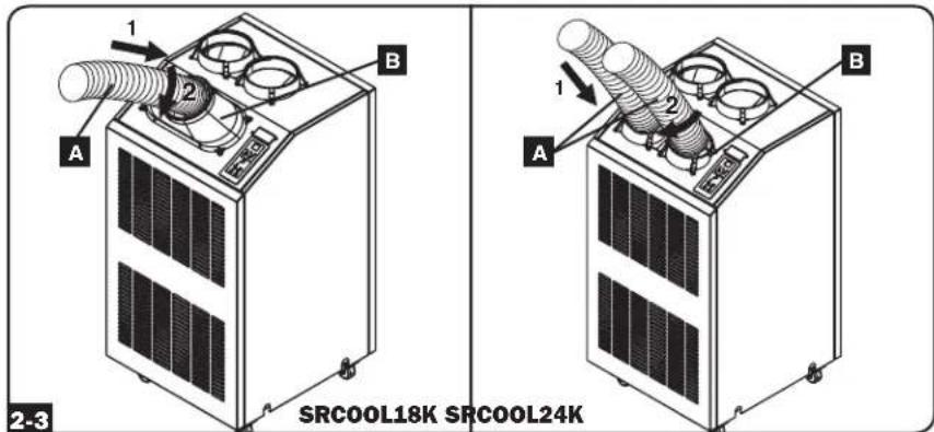
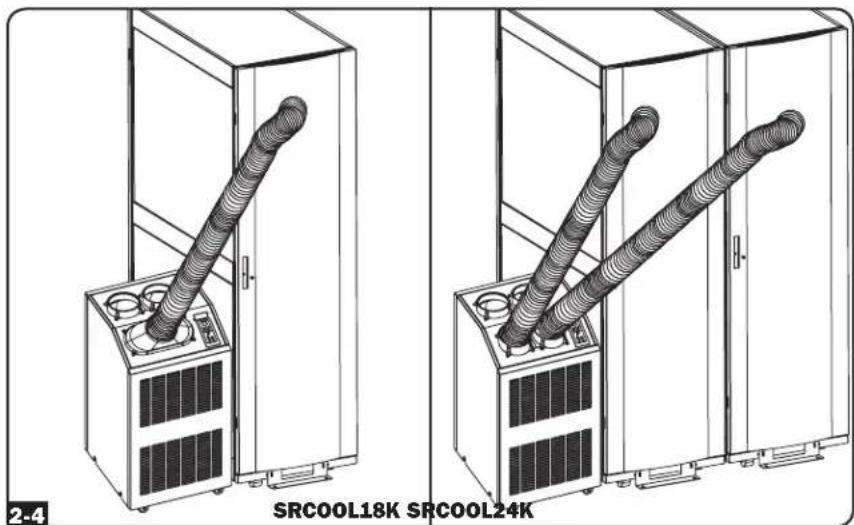
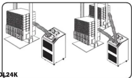
2-4 Place the other end of the cooling duct near the air intake of the target device or rack enclosure, using the straightest, shortest path available (for SRCOOL24K, repeat with the second cooling duct). If you plan to cool a rack enclosure, place the end of the cooling duct over a perforated area near the top of the enclosure's front door (or near the top of the bank of equipment that requires cooling). Cool air will sink and spread across the air intakes at the front of the rack enclosure.
natural_image
Technical line drawings of two server rack units labeled SRCOOL18K and SRCOOL24K, showing coiled ductwork (no text or symbols on the devices themselves)Installation (continued)
3 Exhaust Duct Connection
Note: The SRCOOL18K and SRCOOL24K both contain two exhaust ducts (one for each warm air exhaust) and two exhaust duct adapters. Repeat steps 3-1 and 3-2 install the second exhaust duct and adapter.
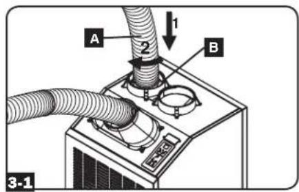
3-1 Connect the flexible gray exhaust duct tube A to the warm air exhaust vent on the rear panel of the unit B. Align the duct with the circular vent opening, push the duct inward and turn the duct clockwise until it screws into the exhaust vent solidly. Repeat for the second exhaust duct tube.
3-2 Connect the other end of the exhaust duct A to the exhaust duct adapter B. Align the duct with the circular adapter opening, push the duct inward and turn the duct clockwise until it screws into the adapter solidly. Repeat for the second exhaust duct tube. If you plan to connect the exhaust duct to a drop ceiling, proceed to step 4. If you plan to connect the exhaust duct to a window, proceed to step 5.

4 Drop Ceiling Exhaust Connection
Note: The SRCOOL18K and SRCOOL24K both contain two adjustable exhaust panels (one for each warm air exhaust duct). Repeat steps 4-1 through 4-4 to install the second exhaust panel.
Warning: Some ceilings may require modified installation procedures. The user must determine the fitness of hardware and procedures before installing. The procedures described in this manual may not be appropriate for all applications. The exhaust panels are not designed to be installed side-by-side.
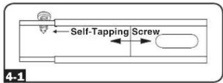
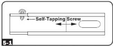
4-1 Choose a removable drop ceiling panel near the unit to provide the straightest, shortest path available for the flexible exhaust duct. Measure the width of the ceiling panel, including the portion that rests on the ceiling grid. Combine the two sections of the adjustable exhaust panel, then adjust the exhaust panel to match the width of the ceiling panel. After the exhaust panel is set to the correct width, use the included self-tapping screw to lock it in place.
Note: The exhaust panel can adjust from 20.5 to 49.2 inches (52.1 to 104.1 cm). Certain installations may require trimming the exhaust panel for a proper fit.
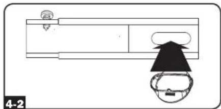
4-2 Insert the exhaust duct adapter into the oblong hole in the adjustable exhaust panel. The adapter will snap into place.
natural_image
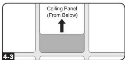
Top-down schematic of a device layout with labeled components and a circular component (no text or symbols)4-3 Slide the ceiling panel out of the way and place the exhaust panel inside the ceiling space. Allow the exhaust panel to rest on top of the ceiling grid.
Note: There must be at least 10 inches (25.4 cm) of open space above the exhaust panel to allow adequate airflow.
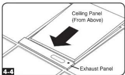
4-4 Slide the ceiling panel back into place so that it adjoins the exhaust panel and closes any gaps in the ceiling. A tight seal will permit maximum cooling efficiency. If the installation is permanent, trim the ceiling panel so it doesn't overlap the ceiling grid. Repeat for the second exhaust duct tube.
Note: The flexible exhaust duct can extend to a maximum length of 118 inches (300 cm). Provide the straightest, shortest path available. Excessive bending or stretching of the duct will reduce cooling efficiency.
After completing step 4, proceed to step 6.
Installation (continued)
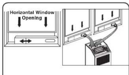
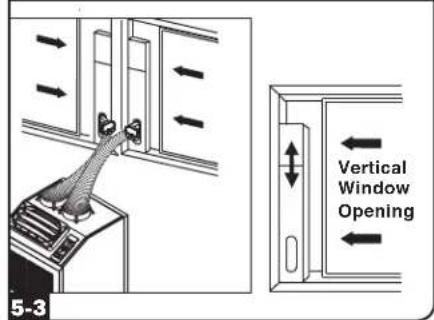
5 Window Exhaust Connection
Note: The SRCOOL18K and SRCOOL24K both contain two adjustable exhaust panels (one for each warm air exhaust duct). Repeat steps 5-1 through 5-3 to install the second exhaust panel.
Warning: Some windows may require modified installation procedures. The user must determine the fitness of hardware and procedures before installing. The procedures described in this manual may not be appropriate for all applications. The exhaust panels are not designed to be installed stacked on top of one another or side-by-side. Each exhaust panel can occupy one window pane.
5-1 Measure the window opening. Combine the two sections of the adjustable exhaust panel, then adjust the exhaust panel to match the width of the window opening. After the exhaust panel is set to the correct width, use the included self-tapping screw to lock it in place.
Note: The exhaust panel can adjust from 20.5 to 49.2 inches (52.1 to 104.1 cm). It is compatible with vertical and horizontal mounting.
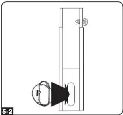
5-2 Insert the exhaust duct adapter into the oblong hole in the adjustable exhaust panel. The adapter will snap into place. Repeat for the second exhaust duct tube.

natural_image
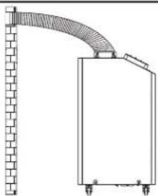
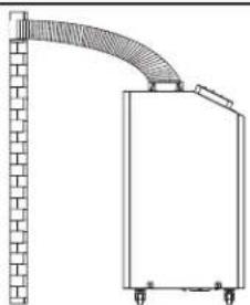
Diagram of a vertical structure with an arrow pointing to a circular component, labeled '5-2' (no text or symbols on the diagram itself)5-3 Insert the exhaust panels into the window opening, then close the window against the exhaust panels. A tight seal will permit maximum cooling efficiency.
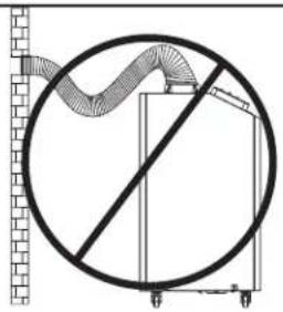
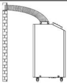
Note: There must be at least 20 inches (50.8 cm) of open space behind the rear panel to allow adequate airflow.
Note: The flexible exhaust duct can extend to a maximum length of 118 inches (300 cm). Provide the straightest, shortest path available. Excessive bending or stretching of the duct will reduce cooling efficiency.
natural_image
Diagram showing a circular structure with a wavy line and a diagonal line, possibly indicating a mechanical or electrical component (no text or symbols present)INCORRECT
natural_image
Technical line drawing of a mechanical or industrial component with a curved pipe and vertical wall (no text or symbols)CORRECT
Installation (continued)
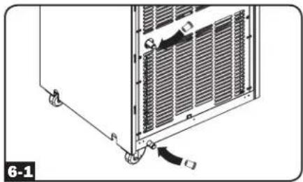
6 Drainage Plug Insertion
Warning: The unit's built-in re-evaporator will not function until you insert the drainage plug into the drainage outlet.
When the unit cools or dehumidifies, condensation forms. The unit has a built-in re-evaporator that allows it to expel condensation through the warm air exhaust stream. This feature allows the unit to operate indefinitely without requiring you to empty a water collection tank. The unit ships with both the upper and lower drainage plugs pre-installed.
6-1 Cooling Mode with Re-Evaporation
This is the default mode of operation.
Note: Both drainage plugs must remain installed to enable re-evaporation of condensation.
natural_image
Diagram of a server rack with heat exchangers and a cable, labeled '6-1' (no text or symbols on the diagram itself)6-2 Cooling Mode without Re-Evaporation
Use this mode in high humidity environments when the unit's capacity to evaporate condensation exceeds the amount of condensation produced. Also use this mode during shut downs when the "Water (Tank) Full" error frequently occurs (see Troubleshooting section for more information on error codes).
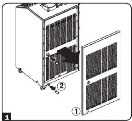
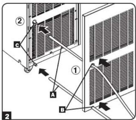
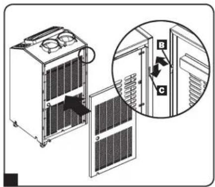
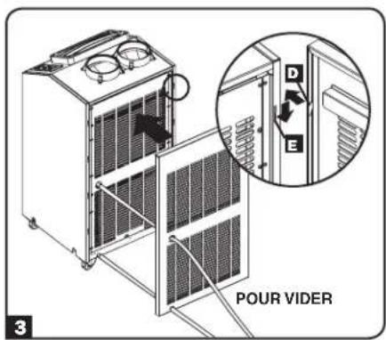
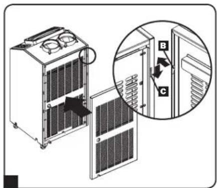
1 Remove the rear panel by lifting it up by its sides to disengage from the unit, then pulling away to detach. Remove the top and bottom drainage plugs.
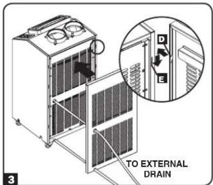
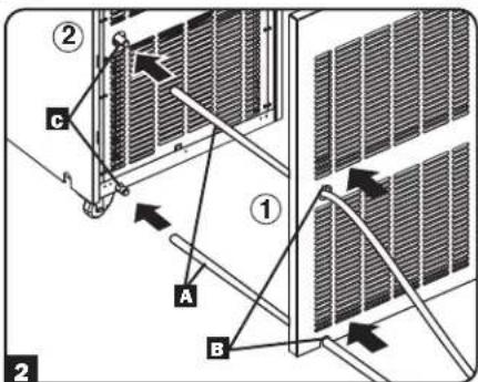
2 Route two user-supplied 3/4 inch or 18 mm drain lines A through the rear panel's top and bottom holes B, and attach to each of the unit's evaporator drainage outlets C, and route the open ends of the drain lines to external drainage.
3 To reattach the rear panel, align the panel hooks D with the unit's slots E, push in to engage, then push down to secure the panel to the unit.
6-3 Dehumidify Mode
Use this mode in environments where the air temperature is already cold (68°F / 20°C or less).
1 Remove the rear panel by lifting it up by its sides to disengage from the unit, then pulling away to detach. Remove the top and bottom drainage plugs.
2 Route two user-supplied 3/4 inch or 18 mm drain lines A through the rear panel's top and bottom holes B, and attach to each of the unit's evaporator drainage outlets C, and route the open ends of the drain lines to external drainage.
3 To reattach the rear panel, align the panel hooks D with the unit's slots E, push in to engage, then push down to secure the panel to the unit.
Note: If the drainage system becomes clogged, a small internal reservoir will collect condensation. If the drainage system is not cleared before the internal reservoir fills, the unit will shut down automatically.
Warning: Before connecting the unit to a dedicated drainage system, turn it off and unplug it. There is a risk of electric shock while the unit is plugged in.
Note: If your building's cooling system has night or weekend thermostat setbacks, has periodic shutdowns, or has limited cooling capacity, you may need to consider alternatives to the standard installation. This product is meant to be used as a supplemental cooling device, and cannot make up for significant fluctuations in building temperature or humidity.
Low Temperature Operation
The SRCOOL18K/SRCOOL24K is a high performance cooler capable of producing very cold air output. When using the SRCOOL18K/SRCOOL24K in environments that are already cold (68°F / 20°C or less), Tripp Lite recommends using the Dehumidify Mode only. This will allow the unit to continue to provide supplemental cooling while preventing any evaporator icing issues caused by the low room temperature.
Operation
Warning: Install the unit according to the instructions in the "Installation" section before attempting to operate it.
Power
Turn the unit on or off by pressing the "POWER" button.
The unit has a three-minute compressor delay in order to prevent potential circuit overloads at start up.
Automatic Restart Feature
The unit will turn on and resume operation automatically when power is restored after a power outage. The unit will use the same settings that it used immediately before the power outage occurred. Note: If the power outage is brief, the unit will run the fan alone for three minutes before resuming normal operation. The delay allows the compressor to depressurize so the unit will function properly when it enters Cool mode.
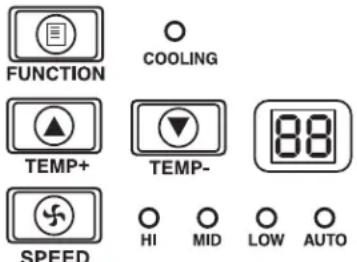
Cool Mode
Pressing the "FUNCTION" button cycles between Cool mode and Dehumidify mode. The "COOLING" LED illuminates when Cool mode is active.
Press the TEMP+ and TEMP- buttons to set the temperature in Cool mode. The selected temperature is shown on the numeric display. Once set, the desired temperature will blink five times after which the display will show the current room temperature.
Press the “FAN SPEED” button to cycle between high, medium and low fan speeds. An LED illuminates to indicate the selected fan speed. When speed is set on AUTO, the unit will automatically select a fan speed based on the set and ambient temperatures. If ambient temperature is lower than the set temperature, the fan will run and the “COOLING” LED will blink to indicate that the compressor is off. When cooling resumes, the “COOLING” LED will remain illuminated.
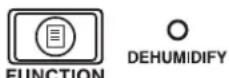
Dehumidify Mode
Pressing the "FUNCTION" button cycles between Cool mode and Dehumidify mode.
The “DEHUMIDIFY” LED illuminates when Dehumidify mode is active. In Dehumidify mode, the fan runs at a fixed speed and temperature controls are irrelevant. For optimal performance in Dehumidify mode, close windows and doors, remove the top drain plug and route user-supplied drain line to external drainage.
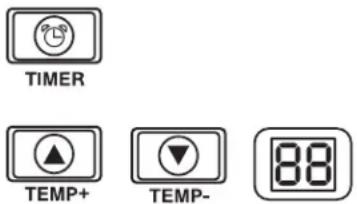
Timer
The "TIMER" button allows you to schedule the unit to turn on or off automatically.
Timer On (Note: The unit must be off to activate the Timer On function. Confirm that mode, temperature and fan speed settings are correct before activating the Timer On function.) Activate the timer by pressing the "TIMER" button. Press the TEMP+ and TEMP- buttons to set the delay (in hours) before the unit will turn on. The number of hours is shown on the numeric display. The number will flash on the screen five times before returning to the current temperature.
Timer Off (Note: The unit must be on to activate the Timer Off function.) Activate the timer by pressing the "TIMER" button. Press the TEMP+ and TEMP- buttons to set the delay (in hours) before the unit will turn off. The number of hours is shown on the numeric display. The number will flash on the screen five times before returning to the current temperature.
Quiet Control Mode
The unit includes a Quiet Control mode which regulates the cooling via the timer and microprocessor to achieve quieter operation levels when noise is an issue.
To activate, press the "QUIET" button. The Quiet LED will turn on. Set the desired temperature and then set the timer to the duration of the Quiet Control mode cycle. During the course of the cycle, the microprocessor memory will adjust the preset temperature by 0.9^ (0.5^) every 30 minutes until it reaches the desired temperature. Once the temperature is reached, the unit will maintain the temperature for the duration of the set time.
Changing Degree Units
The unit can display temperature in both Celsius and Fahrenheit. The default setting is Fahrenheit.
To toggle between temperature modes, put the unit in standby mode. The air conditioner is in standby mode when it is plugged into live AC power, but powered off. Then, hold the "FUNCTION" key for 10 seconds. To verify the degree units have changed, power on the unit.
Operation (continued)
Alarm
When the water tank is full, the unit will display the message "E4" on its screen. To resume normal function, turn the unit off, remove the drainage plug and drain the excess water from the unit. Replace the plug and turn the unit on to begin cooling.
O
ALARM
Maintenance
Periodic maintenance extends the unit's lifespan and permits maximum operating efficiency.
Replacing the Air Filters
The SRCOOL18K and SRCOOL24K use replaceable air filters available for purchase at your local hardware or home improvement store (two per front and rear panel, see below for filter dimensions). It is important to keep the air filters clean and free of dust. When the filters are dirty or clogged with dust, it decreases cooling efficiency and can threaten air quality. Tripp Lite recommends cleaning the filters at least once every two weeks.
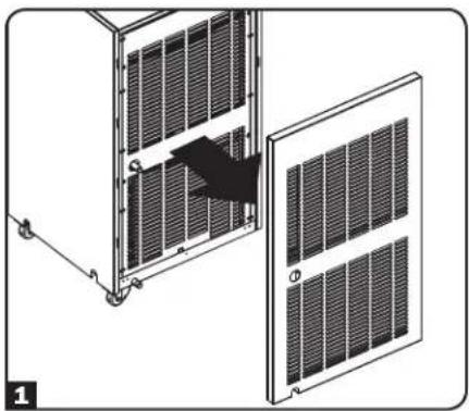
Filter Replacement (Front and Rear Panels)
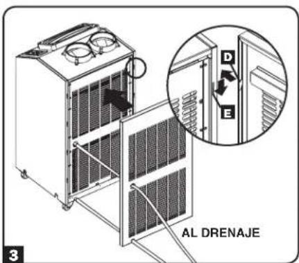
1 Remove the panel by lifting it up by its sides to disengage from the unit, then pulling away to detach.
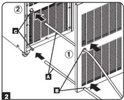
2 On the inside of the front panel, replace both of the used filters with two new filters A (see table below for filter dimensions).
3 To reattach the panel, align the panel hooks B with the unit's slots C, push in to engage, then push down to secure the panel to the unit.
| Filter Type Panel Location Number of Filters Filter Dimensions | ||
| Condenser Filter Front 2 12 x 18 x 1" | ||
| Evaporator Filter Rear 2 14 x 18 x 1" |
natural_image
Diagram of a solar panel installation showing two panels with a black arrow indicating assembly or movement (no text or symbols present)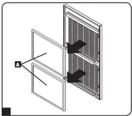
Cleaning the Cabinet

Before cleaning the cabinet, turn the unit off and unplug it! There is a risk of electric shock while the unit is plugged in.
- Turn the unit off and unplug it.
- Wipe the unit with a dry, non-abrasive cloth. Do not use gasoline, benzene, thinners or other harsh chemicals that may damage the surface. Do not pour water directly over the unit or into the working parts. This causes a risk of electrical shock and deterioration of electrical components and wiring insulation.
- In extreme cases, wipe the unit with a damp cloth to remove residue.
Troubleshooting
Review the possible solutions below. If the problem persists, please visit www.tripplite.com/support for service.
| Problem Possible Cause Possible Solution | ||
| The unit does not function. The unit is turned off. Turn the unit on. (See "Operation" section.) | ||
| Cooling performance is unsatisfactory. | The air exhaust or intake is blocked. | Confirm that all ducts and intakes are clear of obstructions. |
| The temperature setting is too high. Adjust the temperature setting. | ||
| The fan speed setting is too low. Adjust the fan setting. | ||
| The air filters are dirty. Clean or replace the air filters. | ||
| The wallage of the rack enclosure, the size of the room or the ambient temperature exceeds the cooling capacity of a single unit. | Install additional units or contact Tripp Lite for additional cooling solutions suitable for your application. | |
| The unit leaks water. | The drainage plug is not installed. | Insert the drainage plug in the drainage outlet. (See "Installation" section.) |
| The unit generates excessive noise or vibration. | The unit is on an uneven or unstable surface. Move the unit to a level, stable surface. | |
| The unit has ice or frost buildup. | The unit is operating in an environment with excess humidity. | OPTION 1: Turn off the unit, and let the unit defrost. Once defrosted, ensure the unit is operating with the fan speed set on HIGH.OPTION 2: Turn off the unit, and let the unit defrost. Once defrosted, operate the unit in DEHUMIDIFY MODE, or increase the desired temperature setpoint. |
Additional Display Codes
Error Codes
The Tripp Lite SRCOOL18K and SRCOOL24K has the ability to continually monitor itself. Should an error occur, the display will show one of 5 codes:
| Error Code | Description |
| E0 | Internal Communication Error |
| E1 | Indoor Temperature Sensor Error |
| E2 | Internal Temperature Sensor Error |
| E3 | Refrigerant Error |
| E4 | Water Full |
Code E4 can be cleared by emptying the water tank. Consult the Alarm entry in the Operation section for details.
For Codes E0, E1, E2, and E3 follow these steps:
- Power cycle the unit by unplugging it from the source for 5 minutes.
- Plug the unit back in.
- Restart the unit.
If the code remains clear, continue to operate the unit as normal. If the code returns, please contact Tripp Lite for further instructions.
dF Code
“dF” will display when the unit detects a condition in which the coil is operating below 33.8^ F ( 1^ C) for more than 15 minutes.
During a dF code event, the unit's fans will run without the compressor to prevent the evaporator from freezing up. Once the coil temperature is above 33.8^ (1^) , the compressor will resume normal operation.
If this condition persists, the unit is operating in an environment that is too cold. Tripp Lite recommends that the unit operate in Dehumidify mode only if operating temperatures are below 68^ F ( 20^ C). See Low Temperature Operation in section 16-3 for more information.
Storage and Service
Storage
Before storing the unit, confirm that the ducts and vents are secured or removed and cared for properly. Also confirm that the unit is drained of condensation.
Service
Your Tripp Lite product is covered by the warranty described in this manual. A variety of Extended Warranty and On-Site Service Programs are also available from Tripp Lite. For more information on service, visit www.triplite.com/support. Before returning your product for service, follow these steps:
- Review the installation and operation procedures in this manual to insure that the service problem does not originate from a misreading of the instructions.
- If the problem continues, do not contact or return the product to the dealer. Instead, visit www.tripplite.com/support.
- If the problem requires service, visit www.triplite.com/support and click the Product Returns link. From here you can request a Returned Material Authorization (RMA) number, which is required for service. This simple on-line form will ask for your unit's model and serial numbers, along with other general purchaser information. The RMA number, along with shipping instructions will be emailed to you. Any damages (direct, indirect, special or consequential) to the product incurred during shipment to Tripp Lite or an authorized Tripp Lite service center is not covered under warranty. Products shipped to Tripp Lite or an authorized Tripp Lite service center must have transportation charges prepaid. Mark the RMA number on the outside of the package. If the product is within its warranty period, enclose a copy of your sales receipt. Return the product for service using an insured carrier to the address given to you when you request the RMA.
Warranty and Product Registration
Warranty
1-YEAR LIMITED WARRANTY
Seller warrants this product, if used in accordance with all applicable instructions, to be free from original defects in material and workmanship for a period of 1 year from the date of initial purchase. If the product should prove defective in material or workmanship within that period, Seller will repair or replace the product, in its sole discretion. Service under this Warranty can only be obtained by your delivering or shipping the product (with all shipping or delivery charges prepaid) to: Tripp Lite, 1111 W. 35th Street, Chicago, IL 60609 USA. Seller will pay return shipping charges.
THIS WARRANTY DOES NOT APPLY TO NORMAL WEAR OR TO DAMAGE RESULTING FROM ACCIDENT, MISUSE, ABUSE OR NEGLECT. SELLER MAKES NO EXPRESS WARRANTIES OTHER THAN THE WARRANTY EXPRESSLY SET FORTH HEREIN. EXCEPT TO THE EXTENT PROHIBITED BY APPLICABLE LAW, ALL IMPLIED WARRANTIES, INCLUDING ALL WARRANTIES OF MERCHANTABILITY OR FITNESS, ARE LIMITED IN DURATION TO THE WARRANTY PERIOD SET FORTH ABOVE; AND THIS WARRANTY EXPRESSLY EXCLUDES ALL INCIDENTAL AND CONSEQUENTIAL DAMAGES. (Some states do not allow limitations on how long an implied warranty lasts, and some states do not allow the exclusion or limitation of incidental or consequential damages, so the above limitations or exclusions may not apply to you. This Warranty gives you specific legal rights, and you may have other rights which vary from jurisdiction to jurisdiction).
WARNING: The individual user should determine prior to use whether this device is suitable, adequate or safe for the use intended. Since individual applications are subject to great variation, the manufacturer makes no representation or warranty as to the suitability or fitness of this device for any specific application.
PRODUCT REGISTRATION
Visit www.triplite.com/warranty today to register your new Tripp Lite product. You'll be automatically entered into a drawing for a chance to win a FREE Tripp Lite product!*
* No purchase necessary. Void where prohibited. Some restrictions apply. Open to U.S. residents only. See www.triplite.com for details.
Regulatory Compliance Identification Numbers
For the purpose of regulatory compliance certifications and identification, your Tripp Lite product has been assigned a unique series number. The series number can be found on the product nameplate label, along with all required approval markings and information. When requesting compliance information for this product, always refer to the series number. The series number should not be confused with the marking name or model number of the product.

WEEE Compliance Information for Tripp Lite Customers and Recyclers (European Union)
Under the Waste Electrical and Electronic Equipment (WEEE) Directive and implementing regulations, when customers buy new electrical and electronic equipment from Tripp Lite they are entitled to:
- Send old equipment for recycling on a one-for-one, like-for-like basis (this varies depending on the country)
- Send the new equipment back for recycling when this ultimately becomes waste
Tripp Lite has a policy of continuous improvement. Product specifications are subject to change without notice.


Manufacturing Excellence.
1111 W. 35th Street, Chicago, IL 60609 USA • www.tripplite.com/support
natural_image
Line drawing of a dual-chamber air conditioning unit with control panel and fan (no text or symbols)Introducción 15
1111 W. 35th Street, Chicago, IL 60609 USA • www.tripplite.com/support
natural_image
Line drawing of a server rack unit with ventilation fans and control panel (no text or symbols)natural_image
Technical line drawing of two industrial equipment units with diagonal bracing (no text or symbols)00L24K
natural_image
Illustration of two server rack setups with a hand operating a control panel (no text or symbols visible)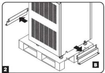
natural_image
Technical diagram of a server rack with mounting bracket and control panel, labeled B (no text or symbols present)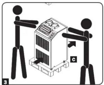
Características
SRCOOL18K/SRCOOL24K
Instalación
natural_image
Technical line drawings of two server rack units labeled SRC00L18K and SRC00L24K, showing coiled ductwork (no text or symbols on the devices themselves)natural_image
Simple line drawing of a table with a lamp and a circular object, no text or symbols present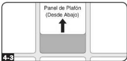
natural_image
Diagram of a vertical structure with a circular component and directional arrow, labeled '5-2' (no text or symbols on the diagram itself)natural_image
Diagram of a circular structure with a diagonal line and wavy top section, possibly indicating a mechanical or structural component (no text or symbols present)INCORRECTO
natural_image
Technical line drawing of a mechanical component with a curved pipe or duct, mounted on a brick wall (no text or symbols)CORRECTO
natural_image
Diagram of a server rack with heat exchangers and a cable, showing no text or symbols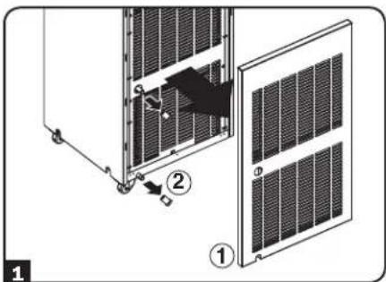
natural_image
Diagram showing two panels of a device with a handle inserted, no text or symbols present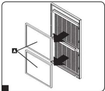
natural_image
Diagram of a solar panel with two arrows pointing to the side panel, labeled 'A' (no text or symbols on panel)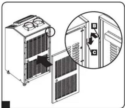
1111 W. 35th Street, Chicago, IL 60609 USA • www.tripplite.com/support
natural_image
Line drawing of a dual-chamber air conditioning unit with ventilation grilles and control panel (no text or symbols)Introduction 28
Manufacturing Excellence.
1111 W. 35th Street, Chicago, IL 60609 USA • www.tripplite.com/support
natural_image
Line drawing of a server rack unit with ventilation fans and control panel (no text or symbols)natural_image
Technical line drawing of two industrial electrical equipment units (SRCOOL18K and SRCOOL24K) with no visible text or symbols on the components themselves.natural_image
Illustration of two industrial systems with control panels and a hand operating it (no text or symbols visible)natural_image
Technical diagram of a server rack with heat exchangers and mounting base (no text or symbols)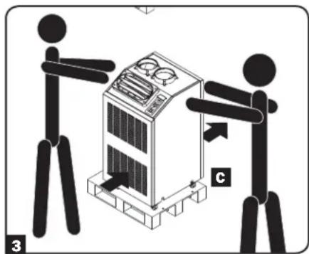
Caractéristiques
SRCOOL18K/SRCOOL24K
Installation (suite)
natural_image
Technical line drawings of server rack units with coiled ducts, no text or symbols presentInstallation (suite)
natural_image
Simple line drawing of a cabinet with an attached lamp and a circular component, no text or symbols present.Installation (suite)
natural_image
Diagram showing a circular structure with a diagonal line and a wavy line above it, next to a brick wall (no text or symbols)INCORRECT
natural_image
Diagram of a vertical wall-mounted device with a curved duct and wheels, no text or symbols presentCORRECT

natural_image
Diagram of a vertical structure with an arrow pointing to a circular component, labeled '5-2' (no text or symbols on the diagram itself)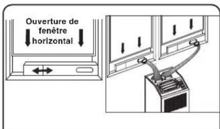
Installation (suite)
natural_image
Diagram of a mechanical assembly with a bracket and mounting feet, showing a fastener or clamp attachment (no text or symbols present)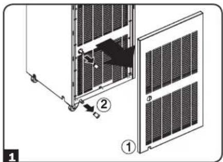
natural_image
Diagram of a solar panel installation showing two panels with a directional arrow indicating movement (no text or symbols present)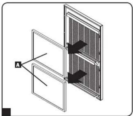
1111 W. 35th Street, Chicago, IL 60609 USA • www.tripplite.com/support


1111 W. 35th Street, Chicago, IL 60609 USA • www.tripplite.com/support