
PDU3XMV6G32 - Power Strip Tripp Lite - Free user manual and instructions
Find the device manual for free PDU3XMV6G32 Tripp Lite in PDF.

| Product Type | Three-phase Power Distribution Unit (PDU) with Instrumentation |
| Model | PDU3XMV6G32 |
| Brand | Tripp Lite |
| Power Input | IEC 309 red 32A 3P+N+T, 360-415V AC, 50/60 Hz |
| Output Voltage | 208-240V AC |
| Total Number of Outlets | 42 (6 rows of 1 C19 outlet + 6 C13 outlets) |
| Circuit Breakers | 6 single-pole, 20A each |
| Maximum Input Current | 32A (limited by cord and plug) |
| Cord Length | 1.8 m (6 ft) |
| Digital Display | 3 digits + 2 digits, displays amperes, kW, voltage, % imbalance |
| LED Indicators per Bank | Green (normal), Yellow (>80% load), Red (under voltage), Red flashing (breaker tripped) |
| Mounting | Rack-mount, with tool-free mounting buttons or included mounting brackets |
| Rotation Accessory | PDUMVROTATEBRKT to orient outputs to the rear of the rack |
| Retention Sleeves | C14 and C20 sleeves included to retain plugs |
| Additional Mounting Hardware | 4 additional mounting buttons included |
| Grounding Screw | Yes |
| Operating Temperature | 0°C to 50°C |
| Usage | Indoor only, controlled environment |
| Warranty | 2-year limited |
| Maintenance | No user-serviceable parts. Clean with a dry cloth. |
Frequently Asked Questions - PDU3XMV6G32 Tripp Lite
User questions about PDU3XMV6G32 Tripp Lite
0 question about this device. Answer the ones you know or ask your own.
Ask a new question about this device
Download the instructions for your Power Strip in PDF format for free! Find your manual PDU3XMV6G32 - Tripp Lite and take your electronic device back in hand. On this page are published all the documents necessary for the use of your device. PDU3XMV6G32 by Tripp Lite.
USER MANUAL PDU3XMV6G32 Tripp Lite
3-Phase Metered 0U Power Distribution Unit
(Phase and Bank Measurements)
PDU3XMV6G32
(Series Number: AG-00BD)
Important Safety Instructions 2
Installation 3
Digital Display 5
Using the Digital Display 6
Features 12
Service 13
Warranty and 14
Product Registration
Español 15
Français 29
Русский 43
Deutsch 57
PROTECT YOUR INVESTMENT!
Register your product for quicker service and ultimate peace of mind.
You could also win an ISOBAR6ULTRA surge protector— a \$100 value!
www.tripplite.com/warranty


TrippLite.Eaton.com/support
Copyright © 2023 Tripp Lite. All rights reserved.
Important Safety Instructions

SAVE THESE INSTRUCTIONS
This manual contains instructions and warnings that should be followed during the installation, operation, and storage of this product. Failure to heed these instructions and warnings may affect the product warranty.
CAUTION Only those who are properly trained or qualified to use this device should do so. Anyone who is not trained or qualified should not use this device unless it is under the supervision of someone who is properly trained or qualified to do so.
Children must be supervised to ensure that they do not use the device as a toy.
Never use the device if the cord and plug are damaged; if it is not working properly, or if it has been dropped or damaged, take it to an authorized service center for inspection and repair.
If the power cord is damaged, it must be replaced by the manufacturer, its authorized service agent, or by qualified personnel in order to avoid a danger.
- The PDU provides the convenience of multiple outlets, but DOES NOT provide surge or line noise protection for connected equipment.
- The PDU is designed for indoor use only, in a controlled environment, away from excess moisture, temperature extremes, conductive contaminants, dust or direct sunlight.
- Keep indoor ambient temperature between 32°F and 122°F (0°C and 50°C).
- The PDU must be installed by a qualified technician only.
- Do not attempt to mount the PDU to an insecure or unstable surface.
• Install in accordance with National Electrical Code standards. Be sure to use the proper overcurrent protection for the installation, in accordance with the plug/equipment rating. - Connect the PDU to an outlet that is in accordance with your local building codes and that is adequately protected against excess currents, short circuits and earth faults.
- The electrical outlets supplying power to the equipment should be installed near the equipment and easily accessible.
- Do not connect the PDU to an ungrounded outlet or to extension cords or adapters that eliminate the connection to ground.
- Be sure to provide a local disconnect device on any models that are permanently installed without a plug that is easily accessible.
- Never attempt to install electrical equipment during a thunderstorm.
- Individual equipment connected to the PDU should not draw more current than the individual PDU's outlet's rating.
- The total load connected to the PDU must not exceed the maximum load rating for the PDU.
- Do not attempt to modify the PDU, input plugs or power cables.
- Do not drill into or attempt to open any part of the PDU housing. There are no user-serviceable parts inside.
- Do not attempt to use the PDU if any part of it becomes damaged.
- Use of this equipment in life support applications where failure of this equipment can reasonably be expected to cause the failure of the life support equipment or to significantly affect its safety or effectiveness is not recommended. Do not use this equipment in the presence of a flammable anesthetic mixture with air, oxygen or nitrous oxide.
Installation
Mounting the PDU
Note: The illustrations may differ somewhat from your PDU model. Regardless of configuration, the user must determine the fitness of hardware and procedures before mounting. The PDU and included hardware are designed for common rack and rack enclosure types and may not be appropriate for all applications. Exact mounting configurations may vary. Screws for attaching the mounting brackets to the PDU are included. Use only the screws supplied by the manufacturer or their exact equivalent.
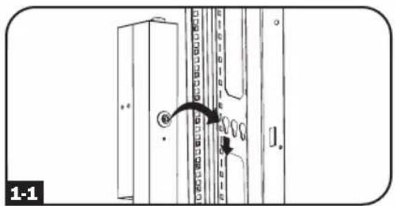
Note: Mounting buttons come preinstalled to the PDU for toolless mounting.
1-1 To mount the PDU using the pre-installed mounting buttons, position the PDU as desired in the rack enclosure, align the buttons with the rack mounting slots, and slide the PDU into position.
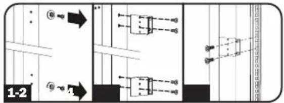
1-2 To attach the mounting brackets to the PDU, remove the mounting buttons.
1-3 Attach the mounting brackets to the PDU with the included screws.
1-4 Attach the PDU to a vertical rail in your rack or rack enclosure. (Use the mounting hardware that came with your rack or rack enclosure to attach the mounting brackets to the rail.)
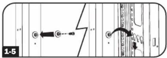
1-5 To reinstall the mounting buttons for toolless mounting, remove the mounting brackets then install the mounting buttons onto the PDU.
Note: Be sure to insert the 2 buttons into either the upper hole at each end of the PDU or into the lower hole at each end of the PDU.
1-6 To install the PDU with its outlets facing the rear of the rack, use the included PDUMVROTATEBRKT accessory. First, attach the mounting button A to the V-shaped bracket B using the included screw and washer. Then, use the button-mount slot to attach the bracket to the PDU and the mounting button to attach the PDU to the rack. The bracket effectively repositions the mounting brackets allowing for the PDU outlets to face the rear of the rack.
![graph TD A["Sensor Input"] --> B{Switch} B --> C["Close"] C --> D["Load"] D --> E["Output"] subgraph Section 1 F["Shake Screen"] --> G["Switch"] G --> H["Close"] H --> I["Load"] I --> J["Output"] subgraph Section 2 K["Shake Screen"] --> L["Switch"] L --> M["Close"] M --> N["Load"] N --> O["Output"]…](/content/2026/03/533537/images/1d57985845918ab52d1906f5ac6ab0822e7b40d4d377881e5461dcd46005c8bb.jpg)
Installation
Connecting the PDU
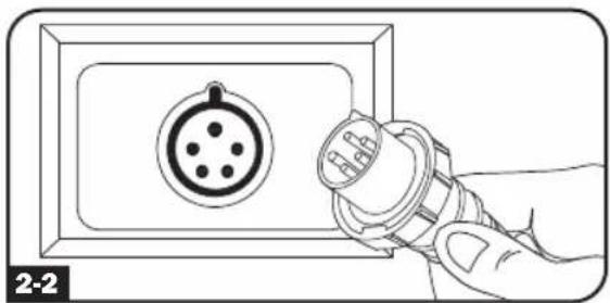
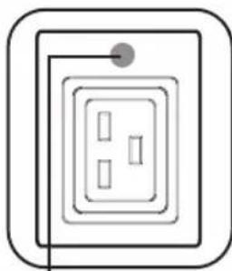
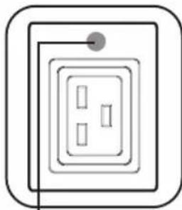
2-1 The PDU3XMV6G32 is equipped with a 32A Red IEC 309 3P + N + E plug.

| Model Name Input | Plug | Max Input Amps (Limited by Input Cord and Plug) | Input Voltage Range | Output Voltage Range Breakers | Cord Length Outlets | |
| PDU3XMV6G32 | 32A Red IEC 309 3P + N + E | 32A 360-415V | 208-240V | 6 x Single Pole, 20A Branch-Rated | 6 ft. (1.8 m) | |
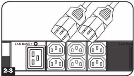
2-2 Connect the input plug to your facility's compatible AC power source.
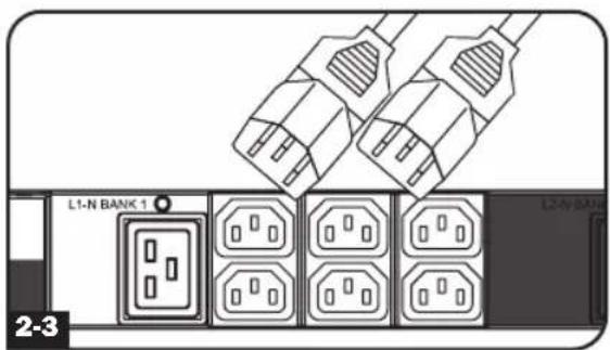
2-3 Connect your equipment's input plugs to the appropriate outlets on the PDU. The LED near each bank illuminates when the bank is ready to distribute live AC power.
Note: It is recommended that you do not connect a live load to the PDU. If the load you intend to connect has an ON/OFF switch, please turn the switch to OFF prior to connection.
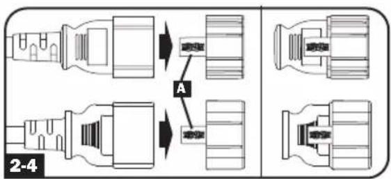
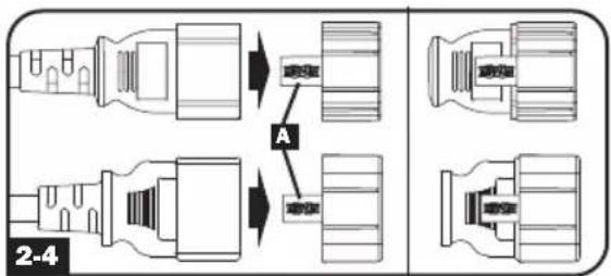
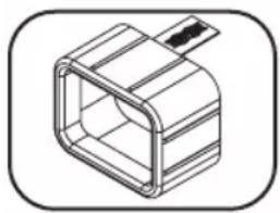
2-4 Optional Cord Retention Procedure
Use the included C14 and C20 plastic sleeves to secure plugs to receptacles. Attach the sleeve to the plug, making sure that the pull tabs A remain outside the plug and that the fit is secure. To unplug equipment properly, use the pull tabs to remove the plug and sleeve from the receptacle.
Digital Display
![graph TD A["INPUT PHASE (L#) UNBALANCED % (UB) LOAD BANK (B#) OUTPUT POWER (OP)"] --> B["MODE"] B --> C["BC"] D["A"] --> E["kW"] E --> F["V"] F --> G["%UB"] G --> H["Output"] I["A"] --> J["Output"] K["BC"] --> L["Output"]](/content/2026/03/533537/images/021725ce7ff941fd227180fba256827c7e380e5a46df249ad10fc64ee7065c90.jpg)
A 3-Digit Display: Shows measured or calculated values such as Amperage, Kilowatts, Voltage and Power Unbalance Percentage.
B Arrow Buttons: Scroll through indicated Input, Bank, Power, Load Balance and Display Brightness options using these buttons. A long press of the up or down arrow buttons allows the user to skip to the next sequential measurement category.
C Mode Button: When a menu option is selected using the Arrow Buttons, the Mode Button scrolls through the sub-options within each category. Sub-options are shown by the Indicator LEDs.
D Indicator LEDs: Lit LED indicates which value is being displayed on the 3-digit screen.
Amps (A): When selected, the load on the selected Input Phase (L#) or Load Bank (B#) is displayed in amps.
Wattage (kW): When selected, the load on the selected Load Bank (B#) or Total Output Power (OP) is displayed in kW.
Voltage (V): Input Phase (L#) or Load Bank (B#) voltage is displayed.
Unbalanced Load (%UB): When lit, the display shows the unbalanced load percentage deviance from the average measured value. A value that is zero or closest to zero is desirable.
E 2-Digit Display: This display indicates which Input Phase (L#), Load Unbalance (UB), Load Bank (B#) or Output Power (OP) option is selected.
Button Response Definitions:
| Switch Action | Control Function | |
| Up Pushbutton | Depress 1/2 sec | Sequentially, moves up one selection in the menu. |
| Depress 3 sec | Advances up to the next measurement category. | |
| Down Pushbutton | Depress 1/2 sec | Sequentially, moves down one selection in the menu. |
| Depress 3 sec | Advances down to the next measurement category. | |
| Mode Pushbutton | Depress 1/2 sec | Displays available options for a given measurement category. |
| Depress 3 sec | Selects the chosen available option for a given configuration category. |
Digital Display
Load Bank Receptacle Location and Display References
PDU3XMV6G32
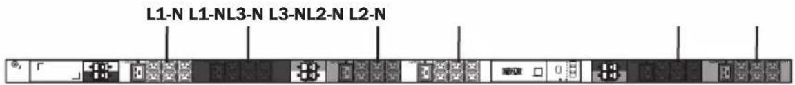
| MODEL SILKSCREEN LABEL DESCRIPTION | 2-DIGIT DISPLAY REFERENCE | |
| PDU3XMV6G32 | L1-N (Bank 1) | B1 |
| L2-N (Bank 2) | B2 | |
| L3-N (Bank 3) | B3 | |
| L1-N (Bank 4) | B4 | |
| L2-N (Bank 5) | B5 | |
| L3-N (Bank 6) | B6 |
INPUT PHASE REFERENCE
| INPUT PHASE REPORTED 2-DIGIT DISPLAY REFERENCE | |
| L1-N | L1 |
| L2-N | L2 |
| L3-N | L3 |
Using the Digital Display
Scrolling Through Input Phases and Options (Measurement Category)
Press Mode button to toggle between options and data within a menu. A momentary press of the arrow buttons switches between menus. A long press skips between measurement categories. The scrolling pattern of the display is outlined below.
Input Phase 1
Amps Volts*
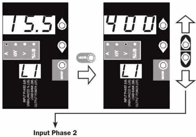
* Note: Voltages displayed are phase-to-phase voltages (i.e., L1 display will indicate L1-L2 voltage).
Using the Digital Display
Input Phase 2
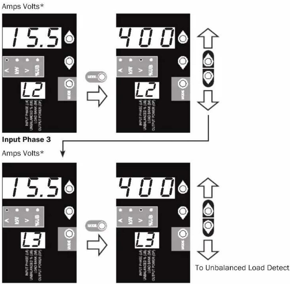
Unbalanced Load Detect (Measurement Category)
Phase Imbalance %

Using the Digital Display
Scrolling Through Load Banks and Options (Measurement Category)
Scroll through the parameter display for each Load Bank using Mode and ↓buttons.
![graph TD A["Amps"] --> B["Kilowatts"] B --> C["Volts"] C --> D["Amps"] D --> E["Kilowatts"] E --> F["Volts"] F --> G["Amps Kilowatts Volts"] subgraph Amps H["10.9 kW V %UB 63"] I["2.18 kW V %UB 63"] J["2.08 kW V %UB 63"] end subgraph Kilowatts K["2.18 kW V %UB 62"] L["2.18 kW V %UB 62"] M["2.08 kW V…](/content/2026/03/533537/images/f1ffe9ac288a2ccbbc593b83bee39ff2e60323b8184afd348d9ecc64cdb0fc7f.jpg)
Note: Continue for Load Banks 4-6.
Using the Digital Display
Press Mode button to toggle between options and data within a menu. A momentary press of the arrow buttons switches between menus. A long press skips between measurement categories. The scrolling pattern of the display is outlined below.
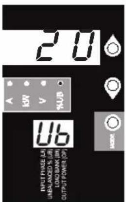
Total Output Power (Measurement Category)
Kilowatts

To Scroll Function Options
Press Mode button to toggle between options and data within a menu. A momentary press of the arrow buttons switches between menus. A long press skips between measurement categories. The scrolling pattern of the display is outlined below.
Scroll Function Options (Configuration Category)
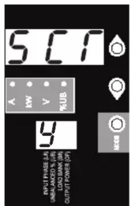

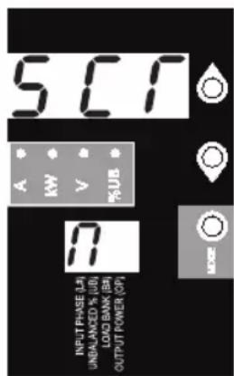

When enabled, the Auto Scroll function displays data for Input Phases, Load Unbalance and Load Banks in 4-second intervals. Y indicates the function is enabled; N indicates that it is disabled. Pressing any button interrupts the auto scroll function, allowing the user to navigate between menu options. If no button is pressed, there is a 10 second timeout.
Note: Hold Mode button for 3 seconds to switch between options. The letter in the 2-digit display indicates the selected option.
Using the Digital Display
LED Brightness and Color Scheme (Configuration Category)
Hold the Mode button for 3 seconds to scroll through each option. The number in the 2-digit display is defined as: 1=25%; 2=50%; 3=75%; 4=100%
![graph TD A["Input Phase Ia UNbalanced % UII LOAD BANK BE OUTPUT POWER OP"] --> B["4"] B --> C["MODE"] C --> D["LED"] D --> E["1"] E --> F["MODE"] F --> G["2"] G --> H["MODE"] H --> I["LED"] I --> J["3"] J --> K["MODE"] K --> L["LED"] L --> M["IND"] M --> N["MODE"] N --> O["2"] O --> P["MODE"] P -->…](/content/2026/03/533537/images/f7e4064d9d080f1ecdfd3651d25fbeb540bca2532143124e3e661ef2b689031a.jpg)
Hold the Mode button for 3 seconds to switch between options. The number in the 2-digit display indicates the selected scheme. 1=Standard, 2=Alternate
Using the Digital Display
BANK INDICATOR LED DEFINITIONS:
| LED Configuration | LED Color Bank Status | Description | |
| Standard1 | Off Off Bank power is absent | ||
| Green On Circuit breaker is on - Bank power is present | |||
| Yellow On | Bank has exceeded 80% of its current rating - Bank power is present | ||
| Red Off | Bank is below the Low Voltage threshold - Bank is disabled | ||
| Red Flashing Off Circuit breaker has tripped - Bank power is absent | |||
| Alternate | Off Off Bank power is absent | ||
| Red On Circuit breaker is on - Bank power is present | |||
| Red Flashing On | Bank has exceeded 80% of its current rating - Bank power is present | ||
| Green Off | Bank is below the Low Voltage threshold - Bank is disabled | ||
| Green Flashing Off Circuit breaker has tripped - Bank power is absent | |||
1 This is the default configuration.
Display Options
LED Test
Hold the Mode button for 3 seconds to test the display. For 5 seconds, all LEDs and display segments will light green, while all Load Indicator LEDs will light yellow. Please visit www.tripplite.com/support for issues with display segment or Indicator LED functionality.
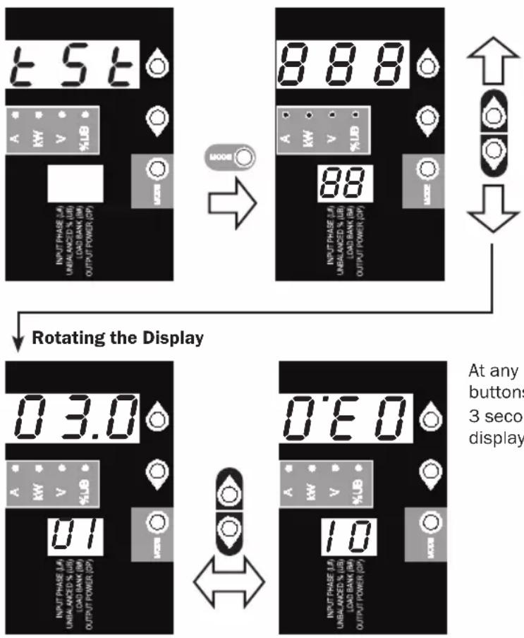
At any point, pressing both of the arrow buttons simultaneously and holding for 3 seconds rotates the 2-digit and 3-digit displays.
Features
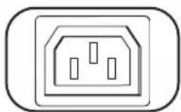
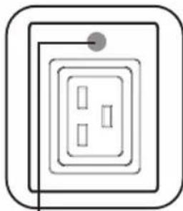
C13
Outlets: During normal operation, the outlets distribute AC power to connected equipment.
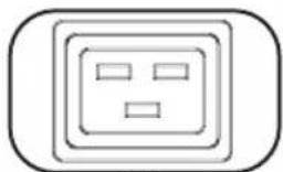
C19
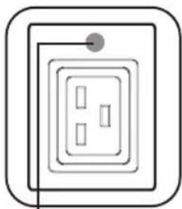
Bank Status LED
Bank Status LED: Once the unit is powered on, each Bank Status LED will illuminate when the associated bank is ready to distribute live AC power.
| LED Color Bank Status Comments/Notes | |
| Green On Normal operation. | |
| Yellow On Bank's current has exceeded 80% of its current rating. | |
| Red Off Bank's voltage is below the Low Voltage threshold. | |
| Red Flashing Off Circuit breaker for this bank has tripped. | |
| Off Off Bank is powered off. | |
Note: Colors noted here reflect standard LED configuration. See chart on page 9 for full LED color definitions.
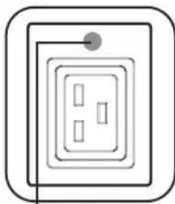
Push-to-Reset Guard
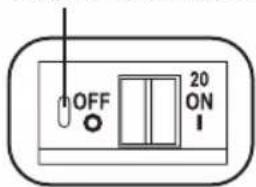
Circuit Breaker: Each Load Bank is protected by a circuit breaker. If the connected equipment load exceeds the Maximum Load Rating for those banks of the PDU, the circuit breaker will trip. Disconnect excess load and reset the breaker.
Note: Each breaker comes equipped with a push-to-reset guard to prevent accidental breaker tripping. To turn off the breaker, insert a flathead screwdriver into the reset slot.
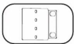
Mounting Brackets: Use these brackets as an alternate PDU mounting method.
Mounting Buttons: Come pre-installed on the back side of the PDU and are used for toolless mounting.
Note: Four additional mounting buttons are included for alternate rack styles.

PDUMVROTATEBRKT Mounting Accessory: Use these V-shaped brackets to mount the PDU with its outlets facing the rear of the rack.
Features
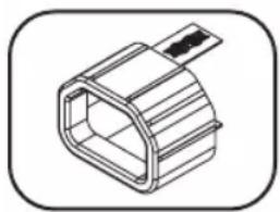
C14 Plug Sleeve: (Optional) Use the included C14 plastic sleeves to secure plugs to receptacles. Attach the sleeve to the plug making sure that the pull tabs remain outside the plug and that the fit is secure. To unplug equipment properly, use the pull tabs to remove the plug and sleeve from the receptacle.

C20 Plug Sleeve: (Optional) Use the included C20 plastic sleeves to secure plugs to receptacles. Attach the sleeve to the plug making sure that the pull tabs remain outside the plug and that the fit is secure. To unplug equipment properly, use the pull tabs to remove the plug and sleeve from the receptacle.

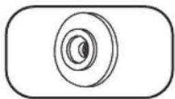
Ground Screw: Use this to connect any equipment that requires a chassis ground.
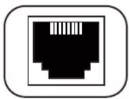
RJ-45 Configuration Port: For factory use only.
Service
Your Tripp Lite product is covered by the warranty described in this manual. A variety of Extended Warranty and On-Site Service Programs are also available from Tripp Lite. For more information on service, visit www.tripplite.com/support. Before returning your product for service, follow these steps:
- Review the installation and operation procedures in this manual to ensure that the service problem does not originate from a misreading of the instructions.
- If the problem continues, do not contact or return the product to the dealer. Instead, visit www.tripplite.com/support.
- If the problem requires service, visit www.tripplite.com/support and click the Product Returns link. From here you can request a Returned Material Authorization (RMA) number, which is required for service. This simple on-line form will ask for your unit's model and serial numbers, along with other general purchaser information. The RMA number, along with shipping instructions will be emailed to you. Any damages (direct, indirect, special or consequential) to the product incurred during shipment to Tripp Lite or an authorized Tripp Lite service center is not covered under warranty. Products shipped to Tripp Lite or an authorized Tripp Lite service center must have transportation charges prepaid. Mark the RMA number on the outside of the package. If the product is within its warranty period, enclose a copy of your sales receipt. Return the product for service using an insured carrier to the address given to you when you request the RMA.
Warranty and Product Registration
2- YEAR LIMITED WARRANTY
Seller warrants this product, if used in accordance with all applicable instructions, to be free from original defects in material and workmanship for a period of 2 years from the date of initial purchase. If the product should prove defective in material or workmanship within that period, Seller will repair or replace the product, in its sole discretion. Service under this Warranty can only be obtained by your delivering or shipping the product (with all shipping or delivery charges prepaid) to: Tripp Lite, 1111 W. 35th Street, Chicago, IL 60609 USA. Seller will pay return shipping charges. Visit www.triplite.com/support before sending any equipment back for repair.
THIS WARRANTY DOES NOT APPLY TO NORMAL WEAR OR TO DAMAGE RESULTING FROM ACCIDENT, MISUSE, ABUSE OR NEGLECT. SELLER MAKES NO EXPRESS WARRANTIES OTHER THAN THE WARRANTY EXPRESSLY SET FORTH HEREIN. EXCEPT TO THE EXTENT PROHIBITED BY APPLICABLE LAW, ALL IMPLIED WARRANTIES, INCLUDING ALL WARRANTIES OF MERCHANTABILITY OR FITNESS, ARE LIMITED IN DURATION TO THE WARRANTY PERIOD SET FORTH ABOVE; AND THIS WARRANTY EXPRESSLY EXCLUDES ALL INCIDENTAL AND CONSEQUENTIAL DAMAGES. (Some states do not allow limitations on how long an implied warranty lasts, and some states do not allow the exclusion or limitation of incidental or consequential damages, so the above limitations or exclusions may not apply to you. This Warranty gives you specific legal rights, and you may have other rights which vary from jurisdiction to jurisdiction).
WARNING: The individual user should take care to determine prior to use whether this device is suitable, adequate or safe for the use intended. Since individual applications are subject to great variation, the manufacturer makes no representation or warranty as to the suitability or fitness of these devices for any specific application.
PRODUCT REGISTRATION
Visit www.triplite.com/warranty today to register your new Tripp Lite product. You'll be automatically entered into a drawing for a chance to win a FREE Tripp Lite product!*
* No purchase necessary. Void where prohibited. Some restrictions apply. See website for details.
FCC Notice, Class A
This device complies with part 15 of the FCC Rules. Operation is subject to the following two conditions: (1) This device may not cause harmful interference, and (2) this device must accept any interference received, including interference that may cause undesired operation.
Note: This equipment has been tested and found to comply with the limits for a Class A digital device, pursuant to part 15 of the FCC Rules. These limits are designed to provide reasonable protection against harmful interference when the equipment is operated in a commercial environment. This equipment generates, uses, and can radiate radio frequency energy and, if not installed and used in accordance with the instruction manual, may cause harmful interference to radio communications. Operation of this equipment in a residential area is likely to cause harmful interference in which case the user will be required to correct the interference at his own expense. The user must use shielded cables and connectors with this equipment. Any changes or modifications to this equipment not expressly approved by Tripp Lite could void the user's authority to operate this equipment.
Regulatory Compliance Identification Numbers
For the purpose of regulatory compliance certifications and identification, your Tripp Lite product has been assigned a unique series number. The series number can be found on the product nameplate label, along with all required approval markings and information. When requesting compliance information for this product, always refer to the series number. The series number should not be confused with the marking name or model number of the product.
WEEE Compliance Information for Tripp Lite Customers and Recyclers (European Union)

Under the Waste Electrical and Electronic Equipment (WEEE) Directive and implementing regulations, when customers buy new electrical and electronic equipment from Tripp Lite they are entitled to:
- Send old equipment for recycling on a one-for-one, like-for-like basis (this varies depending on the country)
- Send the new equipment back for recycling when this ultimately becomes waste
The policy of Tripp Lite is one of continuous improvement. Specifications are subject to change without notice.

TrippLite.Eaton.com/support
| MODELO DESCRIPCIÓN DE ETIQUETA DE SERIGRAFÍA REFERENCIA DE PANTALLA DE 2 DÍGITOS | ||
| PDU3XMV6G32 | L1-N (Banco 1) | B1 |
| L2-N (Banco 2) | B2 | |
| L3-N (Banco 3) | B3 | |
| L1-N (Banco 4) | B4 | |
| L2-N (Banco 5) | B5 | |
| L3-N (Banco 6) | B6 | |
C13
C19
Installation
C13
C19
DEL d'état du banc
C13
C19
Installation 59 English 1
Digitalanzeige
![graph TD A["INPUT PHASE (L#) UNBALANCED % (UB) LOAD BANK (B#) OUTPUT POWER (OP)"] --> B["MODE"] B --> C["BC"] D["A"] --> E["kW"] E --> F["V"] F --> G["%UB"] G --> H["Output"] I["A"] --> J["Output"] K["BC"] --> L["Output"]](/content/2026/03/533537/images/74d6b4119dd8a72342f96864418b1e9218953d782208d4d8b45d22a68b928447.jpg)

Zur LED-
Helligkeit
C13
C19
Bank-Status-LED


The Ground Truth image displays a single, solid horizontal line. According to Rule 2 (UNDERSCORE & LINE RULES), this is a stylistic or background line, not a placeholder underscore. Therefore, the OCR result must ignore it and output nothing or only meaningful text. The provided OCR content is "____", which consists of four underscores. This is an incorrect interpretation of the line as a placeholder, violating the rule that stylistic lines must be ignored. The OCR has hallucinated underscores where none should exist based on the GT's visual context. Hence, the OCR result is inconsistent with the Ground Truth.


- 3-PHASE METERED 0U POWER DISTRIBUTION UNIT
- PROTECT YOUR INVESTMENT
- IMPORTANT SAFETY INSTRUCTIONS
- SAVE THESE INSTRUCTIONS
- INSTALLATION
- MOUNTING THE PDU
- CONNECTING THE PDU
- DIGITAL DISPLAY
- LOAD BANK RECEPTACLE LOCATION AND DISPLAY REFERENCES
- USING THE DIGITAL DISPLAY
- SCROLLING THROUGH INPUT PHASES AND OPTIONS (MEASUREMENT CATEGORY)
- SCROLLING THROUGH LOAD BANKS AND OPTIONS (MEASUREMENT CATEGORY)
- TOTAL OUTPUT POWER (MEASUREMENT CATEGORY)
- SCROLL FUNCTION OPTIONS (CONFIGURATION CATEGORY)
- LED BRIGHTNESS AND COLOR SCHEME (CONFIGURATION CATEGORY)
- DISPLAY OPTIONS
- LED TEST
- FEATURES
- SERVICE
- WARRANTY AND PRODUCT REGISTRATION
- YEAR LIMITED WARRANTY
- PRODUCT REGISTRATION
- FCC NOTICE, CLASS A
- REGULATORY COMPLIANCE IDENTIFICATION NUMBERS
- WEEE COMPLIANCE INFORMATION FOR TRIPP LITE CUSTOMERS AND RECYCLERS (EUROPEAN UNION)
- DIGITALANZEIGE
Brand : Tripp Lite
Model : PDU3XMV6G32
Category : Power Strip