B127E1A1HH - Receiver Tripp Lite - Free user manual and instructions
Find the device manual for free B127E1A1HH Tripp Lite in PDF.
| Product Type | HDMI over IP Receiver |
| Brand | Tripp Lite |
| Model | B127E1A1HH |
| Supported Resolution | Up to 4K (3840 x 2160) @ 60 Hz 4:4:4 |
| Maximum Distance | Up to 100 m (328 ft) via Cat6 cable |
| Power Supply | Power over Cable (PoC) – powered by transmitter via Cat6 cable |
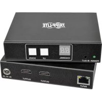
| Connectors | HDMI (input), RJ45, 2x USB-A, 2x 3.5 mm IR jacks, RS-232 (3-pin phoenix) |
| Supported Audio | Surround sound up to 7.1 channels |
| HDMI Compatibility | HDMI 2.0, HDCP 2.2 |
| Mounting | Wall, 19" rack, pole (hardware included) |
| Remote Control | Bi-directional IR, RS-232, USB 1.1 (keyboard/mouse) |
| Dimensions (approx.) | 10.2 x 8.1 x 2.5 cm |
| Weight (approx.) | 200 g |
| Plug and Play | Yes, no driver required |
| Warranty | Limited 1-year warranty |
| Included Accessories | IR cables, RS-232 adapters, mounting hardware, user manual |
Frequently Asked Questions - B127E1A1HH Tripp Lite
User questions about B127E1A1HH Tripp Lite
0 question about this device. Answer the ones you know or ask your own.
Ask a new question about this device
Download the instructions for your Receiver in PDF format for free! Find your manual B127E1A1HH - Tripp Lite and take your electronic device back in hand. On this page are published all the documents necessary for the use of your device. B127E1A1HH by Tripp Lite.
USER MANUAL B127E1A1HH Tripp Lite
4K HDMI Over Cat6 Extender Kit
Model:
B127E-1A1-HH
text_image
ETN TRIPP LTE (8002) STRASMT75.0 ETN TRIPP LTE (8003) POWER To GOA UK 8001 BLOO H210 H210 H210 H210 H210 H210 H210 H210 H210 H210 H210 H210 H210 H210 H210 H210 H210 H210 H210 H210 H215 H215 H215 H215 H215 H215 H215 H215 H215 H215 H215 H215 H215 H215 H215 H215 H215 H215 H215 H215 H210 H210 H210 H210 H210 H210 H210 H210 H210 H210 H210 H210 H210 H210 H210 H210 H210 H210 H210 H214 H214 H214 H214 H214 H214 H214 H214 H214 H214 H214 H214 H214 H214 H214 H214 H214 H214 H214 H214 H216 H216 H216 H216 H216 H216 H216 H216 H216 H216 H216 H216 H216 H216 H216 H216 H216 H216Purchased product may differ from image.
Español 9
Français 18
Deutsch 27
Italiano 36
Package Contents
• Transmitter and Receiver Units
• External Power Supply Plug Adapters: AS/NZS 3112 Australia; BS 1363 U.K.; CEE 7/16 Schuko; NEMA 1-15P North America
- IR-Out Cable
- IR-In Cable
• (x2) RS-232 Adapters
- Mounting Hardware
- Owner's Manual
Optional Accessories:
• N202-Series Cat6 24 AWG Solid-Wire Patch Cables
• P569-XXX-CERT or P568-XXX-2A Series High-Speed HDMI 2.0 Cables
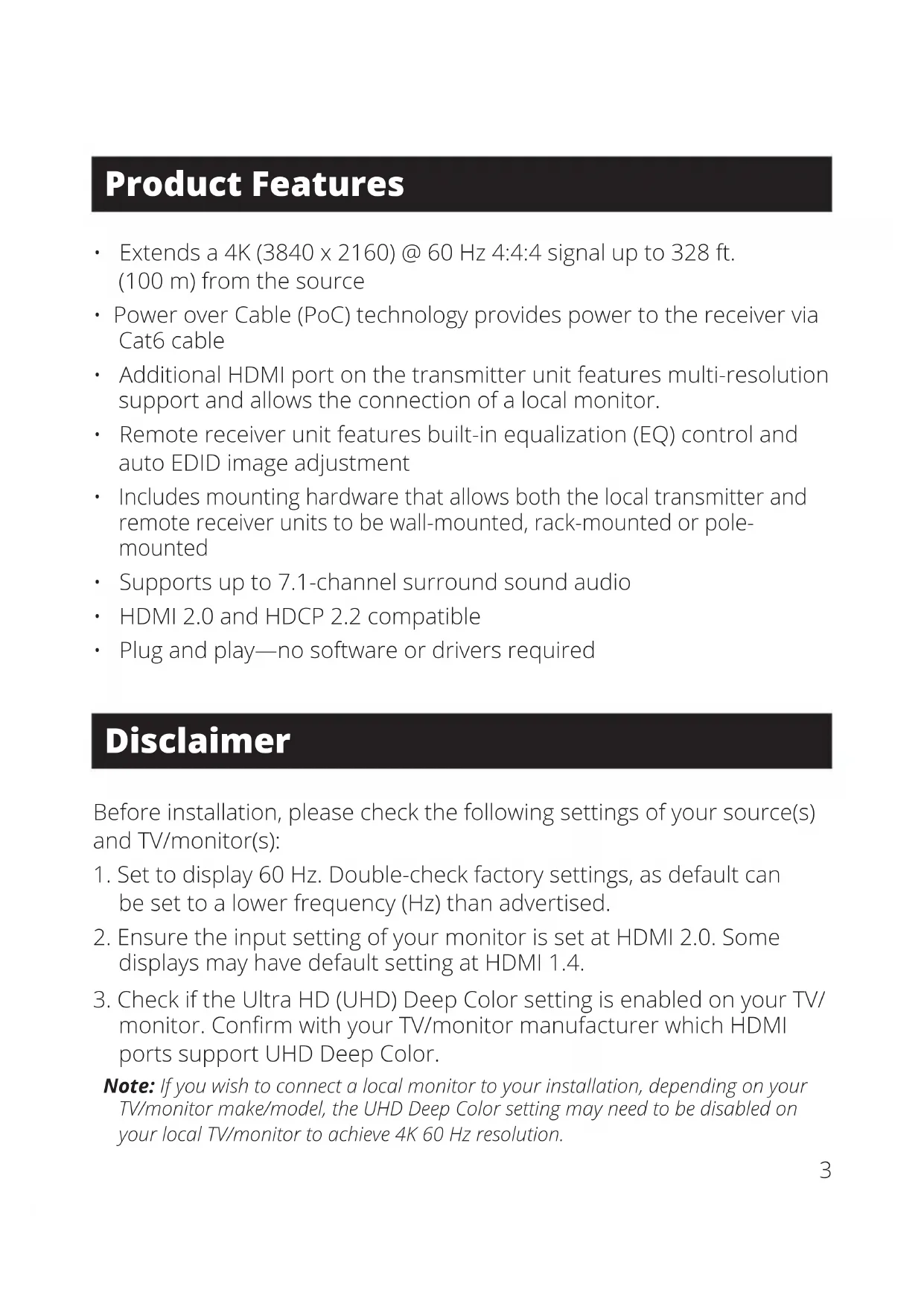
Product Features
- Extends a 4K (3840 x 2160) @ 60 Hz 4:4:4 signal up to 328 ft. (100 m) from the source
- Power over Cable (PoC) technology provides power to the receiver via Cat6 cable
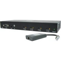
- Additional HDMI port on the transmitter unit features multi-resolution support and allows the connection of a local monitor.
- Remote receiver unit features built-in equalization (EQ) control and auto EDID image adjustment
- Includes mounting hardware that allows both the local transmitter and remote receiver units to be wall-mounted, rack-mounted or pole-mounted
• Supports up to 7.1-channel surround sound audio
• HDMI 2.0 and HDCP 2.2 compatible - Plug and play—no software or drivers required
Disclaimer
Before installation, please check the following settings of your source(s) and TV/monitor(s):
- Set to display 60 Hz. Double-check factory settings, as default can be set to a lower frequency (Hz) than advertised.
- Ensure the input setting of your monitor is set at HDMI 2.0. Some displays may have default setting at HDMI 1.4.
- Check if the Ultra HD (UHD) Deep Color setting is enabled on your TV/monitor. Confirm with your TV/monitor manufacturer which HDMI ports support UHD Deep Color.
Note: If you wish to connect a local monitor to your installation, depending on your TV/monitor make/model, the UHD Deep Color setting may need to be disabled on your local TV/monitor to achieve 4K 60 Hz resolution.
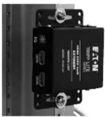
Mounting Instructions (select models only)
The B127E-1A1-HH includes mounting hardware that allows for a variety of mounting methods. The following images illustrate how the included mounting brackets can be attached for different installations.
Note: The model shown in the below images is for illustrative purposes only. Your product may vary by model number, size or port orientation. The mounting options for all over IP units are the same.
Wall-mount
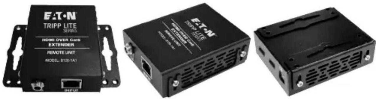
19" Rack-mount Pole-mount
text_image
E-T-N TRIPPU LIFE SUN HAWA OVER-EAS EXTERIOR REWATT LIME MOUNT BEATLE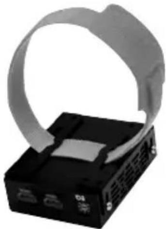
natural_image
Black electronic device with a coiled cable and ventilation slots, no visible text or symbols
natural_image
Close-up of a black mechanical device with a base and top, no visible text or symbolsStandard Extender Kit Installation
Notes:
1) Test to ensure the entire installation works properly before pulling cables through ceilings/walls.
2) To achieve maximum distance and performance, use 24 AWG solid-wire Cat6 cable. Using stranded-wire Cat6 cable, or cable with a gauge (AWG) size higher than 24 AWG, will result in shorter extension distance. Higher gauge cabling, such as 26 AWG, has a more limited transmission capability than lower gauge cabling. N202-Series Cat6 cables are made with 24 AWG solid-wire cabling.
3) The installation diagram shows a B127E-1A1-HH unit.
4) External power is not required for remote receiver units due to Power-over-Cable (PoC) technology incorporated in the transmitter units.
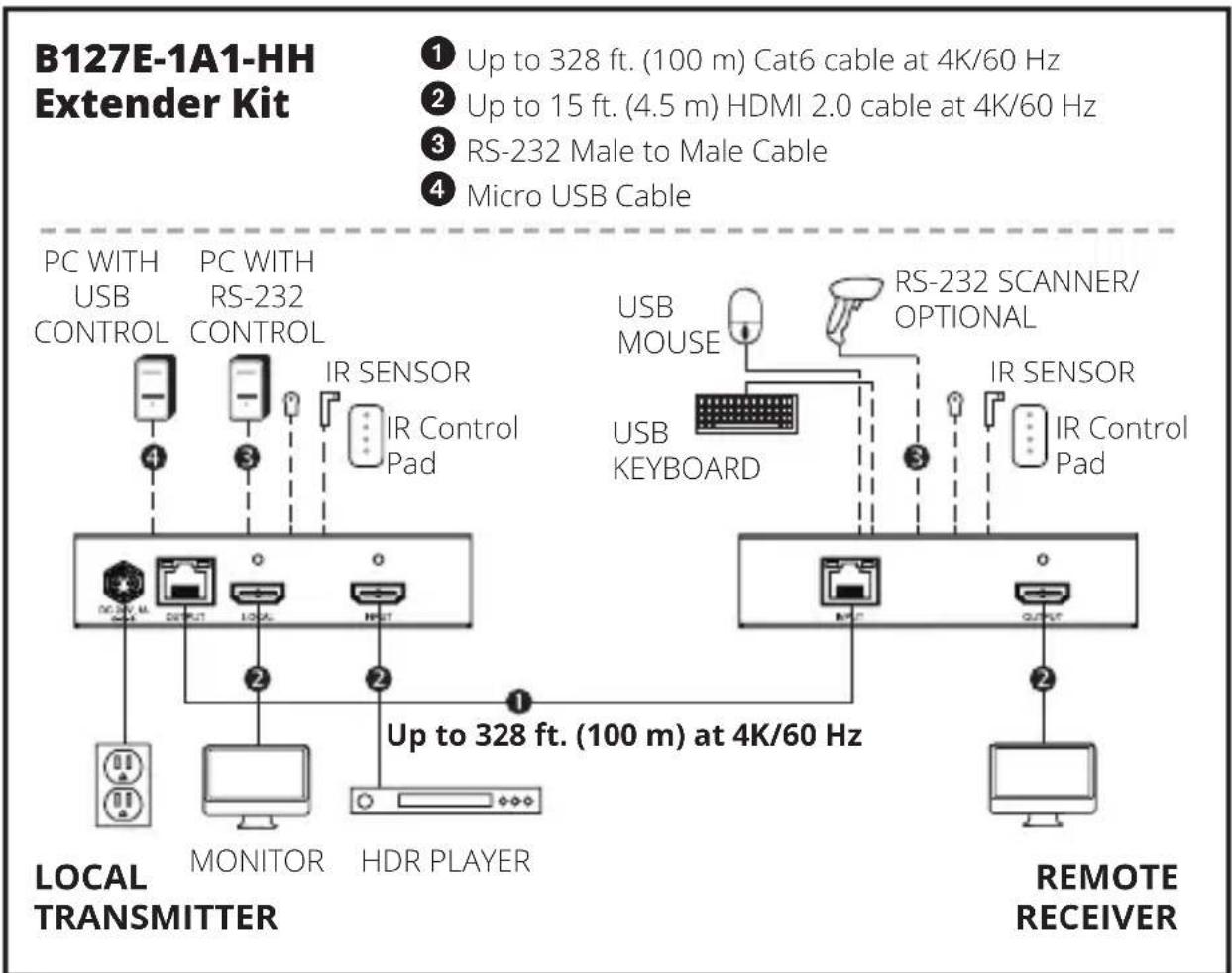
text_image
B127E-1A1-HH Extender Kit ① Up to 328 ft. (100 m) Cat6 cable at 4K/60 Hz ② Up to 15 ft. (4.5 m) HDMI 2.0 cable at 4K/60 Hz ③ RS-232 Male to Male Cable ④ Micro USB Cable PC WITH USB CONTROL PC WITH RS-232 CONTROL IR SENSOR IR Control Pad USB MOUSE RS-232 SCANNER/ OPTIONAL USB KEYBOARD IR SENSOR IR Control Pad DC: 6 V. ML D: 3 V. M. LOCAL MONITOR HDR PLAYER Up to 328 ft. (100 m) at 4K/60 Hz LOCAL TRANSMITTER REMOTE RECEIVERStandard Extender Kit Installation
- Make sure all equipment in the installation—such as TVs, Blu-ray players and the transmitter—is powered OFF.
- Using an HDMI 2.0 cable (such as P569-XXX-CERT or P568-XXX-2A Series cables), connect the HDMI source to the INPUT port on the local transmitter unit.
- Optional: Using an HDMI 2.0 cable (such as P569-XXX-CERT or P568-XXX-2A Series cables), connect a local monitor to the LOCAL port on the B127E-1A1-HH local transmitter unit. Monitors with varying resolutions such as 4K 30Hz or 1080p can be connected without affecting the 4K 60Hz signal transmission.
- Using Cat6 cable up to 328 ft. (100 m), connect the RJ45 port on the local transmitter unit to the RJ45 port on the remote receiver unit.
- Using an HDMI 2.0 cable (such as P569-XXX-CERT or P568-XXX-2A Series cables), connect the remote receiver unit's HDMI port to a monitor.
- Turn the power ON to your connected TVs/monitors. The LOCAL (orange) LED will illuminate to indicate the local port has been connected to a display.
- Connect the external power supply to the local transmitter unit and plug it into an available wall outlet or (optional) a Surge Protector, Power Distribution Unit (PDU) or Uninterruptible Power Supply (UPS). The POWER (green) LED on the local transmitter unit will illuminate to indicate the unit is receiving power from the external power supply. The POWER (green) LED on the remote receiver unit will illuminate to indicate the unit is receiving power from the local transmitter unit through PoC technology.
- Turn ON the power to the HDMI source. The TX (orange) LED on the local transmitter unit illuminates to indicate a signal is being received from the source. The RX (orange) LED on the receiver unit illuminates to indicate a signal is being received from the source to the display.
Standard Extender Kit Installation
- The (orange) Link LEDs will illuminate on both local transmitter and remote receiver units to indicate a successful connection has been made between the two units. The screen should now display on the connected monitor.
USB/IR/RS-232 Controls
The extender kit provides the following functional controls:
- USB 1.1 – One Micro-USB input at transmitter, dual USB-A outputs at receiver
- Bi-Directional IR-Dual 3.5 mm jacks at both the transmitter and receiver
- RS-232 – One 3-pin phoenix connector at both the transmitter and receiver
(Optional) Connect the computer's DB9 port to the transmitter unit's RS-232 serial port. The serial port is a 3-position phoenix connector for RS-232 (DB connector) pin 2, 3 and 7 connection. Connect your RS-232 device (e.g. barcode scanner) to the 3-position phoenix connector on the receiver unit.
(Optional) Connect the included IR-OUT cable to the transmitter unit's IR-OUT port. Place the sensor on the IR-OUT cable in an unobstructed area within clear view of the device being controlled. Then connect the included IR-IN cable to the receiver unit's IR-IN port. The IR-IN cable will communicate the desired command via the transmitter's IR-OUT cable.
Note: The IR-OUT cable receives the signal from the remote control and sends it to the device being controlled (e.g. Blu-ray™ player, etc.).
(Optional) With a user-supplied USB Micro-B cable (such as U050-XXX Series USB cable), connect to the transmitter's Micro-B port. Then connect a keyboard and mouse to the available USB-A ports on the receiver unit.
Warranty
1-Year Limited Warranty
We warrant our products to be free from defects in materials and workmanship for a period of one (1) year from the date of initial purchase. Our obligation under this warranty is limited to repairing or replacing (at its sole option) any such defective products. Visit Tripplite.Eaton.com/support/product-returns before sending any equipment back for repair. This warranty does not apply to equipment which has been damaged by accident, negligence or misapplication or has been altered or modified in any way.
EXCEPT AS PROVIDED HEREIN, WE MAKE NO WARRANTIES, EXPRESS OR IMPLIED, INCLUDING WARRANTIES OF MERCHANTABILITY AND FITNESS FOR A PARTICULAR PURPOSE. Some states do not permit limitation or exclusion of implied warranties; therefore, the aforesaid limitation(s) or exclusion(s) may not apply to the purchaser.
EXCEPT AS PROVIDED ABOVE, IN NO EVENT WILL WE BE LIABLE FOR DIRECT, INDIRECT, SPECIAL, INCIDENTAL OR CONSEQUENTIAL DAMAGES ARISING OUT OF THE USE OF THIS PRODUCT, EVEN IF ADVISED OF THE POSSIBILITY OF SUCH DAMAGE. Specifically, we are not liable for any costs, such as lost profits or revenue, loss of equipment, loss of use of equipment, loss of software, loss of data, costs of substitutes, claims by third parties, or otherwise.
WEEE Compliance Information for Customers and Recyclers (European Union)
Under the Waste Electrical and Electronic Equipment (WEEE) Directive and implementing regulations, when customers buy new electrical and electronic equipment from Eaton, they are entitled to:
- Send old equipment for recycling on a one-for-one, like-for-like basis (this varies depending on the country)
- Send the new equipment back for recycling when this ultimately becomes waste
WARNING
Use of this equipment in life support applications where failure of this equipment can reasonably be expected to cause the failure of the life support equipment or to significantly affect its safety or effectiveness is not recommended.
Eaton has a policy of continuous improvement. Specifications are subject to change without notice. Photos and illustrations may differ slightly from actual products.

Powering Business Worldwide
Eaton
1000 Eaton Boulevard
Cleveland, OH 44122
United States
Eaton.com
© 2024 Eaton
All Rights Reserved
Publication No. 23-09-191 /
93-3B89_RevB
February 2024

933B89
Eaton is a registered trademark.
All trademarks are property of their respective owners.
natural_image
Three black electronic devices labeled E-T-N TRIPP LITE SERIES, EXTENDER, and MODE 8126-1A1, shown from different angles (no visible text or symbols on the devices themselves)natural_image
Three black electronic devices: a E-T-N trip-lite switch, a cable strap device, and a stand-mounted device (no visible text or symbols on the devices themselves)Powering Business Worldwide
Eaton
1000 Eaton Boulevard
Cleveland, OH 44122
Estados Unidos
Eaton.com
© 2024 Eaton
natural_image
Black electronic device with a coiled cable and ventilation slots (no visible text or symbols)
natural_image
Black mechanical device with a base and vertical support, no visible text or symbolsPowering Business Worldwide
Eaton
1000 Eaton Boulevard
Cleveland, OH 44122
États-Unis
Eaton.com
© 2024 Eaton
natural_image
Black plastic electronic device casing with ventilation slots and mounting holes (no visible text or symbols)natural_image
Black electronic device with a coiled cable and ventilation slots, no visible text or symbols
natural_image
Close-up of a black mechanical device with a base and top, no visible text or symbolsPowering Business Worldwide
Eaton
1000 Eaton Boulevard
Cleveland, OH 44122
Vereinigte Staaten
Eaton.com
© 2024 Eaton
natural_image
Two black electronic devices: a circular device with a strap and a vertical stand (no visible text or symbols)Powering Business Worldwide
Eaton
1000 Eaton Boulevard
Cleveland, OH 44122
Stati Uniti
Eaton.com
© 2024 Eaton