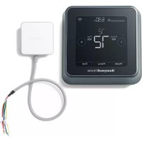
FocusPro TH5320R - Thermostat HONEYWELL - Free user manual and instructions
Find the device manual for free FocusPro TH5320R HONEYWELL in PDF.
Download the instructions for your Thermostat in PDF format for free! Find your manual FocusPro TH5320R - HONEYWELL and take your electronic device back in hand. On this page are published all the documents necessary for the use of your device. FocusPro TH5320R by HONEYWELL.
USER MANUAL FocusPro TH5320R HONEYWELL
RedLINK™ Wireless System With Equipment Interface Module® U.S. Registered Trademark.Copyright © 2011 Honeywell International Inc. All rights reserved. System Installation Guide 69-2091EFS-07 Wireless control for up to 3 Heat/2 Cool heat pump systems or up to 2 Heat/2 Cool conventional systems. Installation guide for:
- Wireless remote control
- Wireless outdoor air sensor
- Return air sensor DISCONNECT POWER BEFORE BEGINNING INSTALLATION. Can cause electrical shock or equipment damage. MERCURY NOTICE: If this product is replacing a control that contains mercury in a sealed tube, do not place the old control in the trash. Contact your local waste management authority for instructions regarding recycling and proper disposal. Must be installed by a trained, experienced technician. Read these instructions carefully. Failure to follow these instructions can damage the product or cause a hazardous condition. Français : voir la page 21 • Español: vea la página 41RedLINK
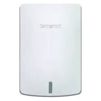
Installation Guide (EIM) 69-2091EFS—07 2 System installation at a glance The THM5320R equipment interface module (EIM) provides control of all heating and cooling equipment from any FocusPRO wireless thermostat. Installation procedure Mount and wire EIM .................................................................. Pages 3-4 Install batteries in wireless devices ...............................................Page 5 Link all devices to wireless network ........................................ Pages 5-7 Exit wireless setup ..........................................................................Page 8 Customize thermostat (installer setup) .................................. Pages 8-12 Mount thermostat and outdoor sensor .......................................Page 13 To replace system components if needed, see page 15 For system-specific wiring guides, see pages 16-17 If you have more than one Equipment Interface Module (EIM): Thermostats are linked to specific EIMs. Optional accessories must be linked to each EIM separately. DISCONNECT POWER BEFORE BEGINNING INSTALLATION. Can cause electrical shock or equipment damage. RemotecontrolThermostatOptional outdoorair sensorM28484HVAC equipment EIM
Mount and wire EIM Mount EIM on wall near HVAC equipment, or on the equipment itself. Do not install inside HVAC equipment. Use screws & anchors as appropriate for mounting surface. EIM wiring
GREEN: CONNECTED TO REMOTE DEVICE(S) CONNECTED POWER HEAT COOL FAN M28468M28469 Install EIM Install return air sensor (optional)** The return air sensor maintains safe indoor temperature (62° F in Heat, 82° F in Cool) if thermostat power is lost. Drill 1/4” hole (6.4mm) Install sensor on return air duct at least 12” (305mm) upstream from ventilator, humidifier or dehumidifier (do not mount downstream) Strip 1/4” insulation, then insert wires as shown. Press tabs only to remove wires from terminal block if necessary. Wiring must comply with local electrical codes. Continued on next page >> ** For hydronic applications, use C7189U1005 Remote Indoor Sensor and mount in the living space.RedLINK
Install batteries in wireless devices When system wiring is complete, install batteries in all devices. Make sure batteries are inserted properly (see polarity marks on illustrations below).
Link all devices to wireless network M28472M28473M28475M28476M28495 Thermostat Remote control (optional) Outdoor air sensor (optional) Restore AC power, then press and release the CONNECT button at the EIM. Wait for green flashing light to begin linking devic- es to the wireless network (see pages 6-7). If the light stops flashing before you have linked all devices, press CONNECT again. If light does not flash, another EIM/ wireless adapter may be in wireless setup mode. Exit wireless setup at the other EIM/wireless adapter. Continued on next page >> Install 2 fresh AA batteries Install quick reference card Programmable models only Install 3 fresh AA batteries Install 2 fresh AA lithium batteries Press and release CONNECT Flashing status light times out after 15 minutes of inactivity. Press CONNECT again if necessary.RedLINK
Wireless Setup Next M28478
Wireless Setup Next BackM28479Wireless SetupConnectBackM28480Wireless SetupConnectedDone Link thermostat to wireless network Zone number Zone name Press NEXT (always leave zone number set to zero). Zone numbers 1-4 are for use with TrueZONE panels only. Press NEXT (or see page 11 to change the zone name if needed). Change zone name only if you have more than one thermostat and EIM. Press CONNECT to establish a link to the wire- less network. If E1 appears, see error codes on page 14. After a brief pause, the confirmation screen at left should be displayed, to verify that the wireless connection has been established. Press DONE to display the home screen.Français : voir la page 21 • Español: vea la página 41 7 69-2091EFS—07 Link remote control to wireless network (optional) Link outdoor sensor to wireless network (optional) CONNECT WIRELESS SETUP M28481M28483 NOYES CONNECT MORE? M28482 1 Make sure the Connected light on the EIM is flashing (see page 5). 2 Press CONNECT at the remote. There will be a short delay as the remote seeks a signal from the wireless network. 3 When the screen displays "Connected," press DONE. 4 Press NO at the next screen to save and exit. (Or press YES and repeat steps 1-4 to link another EIM.) 1 Make sure the Connected light on the EIM is flashing (see page 5). 2 Press and release the CONNECT button on the back of the sensor. 3 Check thermostat to verify that the outdoor sensor is working. After about 15 seconds, the thermostat should display outdoor temperature and humidity. Press to link another EIM Press to save and exit If E1 appears, see error codes on page 14. The linking procedure may time out if there is no keypress within 30 minutes. To begin again, press and hold the blank space (or arrow, if present) in the lower right corner of the screen until the display changes (about 3 seconds). Press and release (If you are installing more than one EIM, repeat steps 1-3 for each.)RedLINK Installation Guide (EIM)69-2091EFS—07 8
Customize thermostat (installer setup) Press CONNECT at the EIM to exit wireless setup (light should stop flashing). Follow the steps below to begin installer setup. At each function screen, press s or t to change the setting as desired, then press NEXT to advance to the next function screen. See tables on pages 9-11 for a description of options for each function. Press s or t to change setting (see tables on pages 9-11).Press NEXT to display next function screen.Note: The EIM will automatically exit wireless setup after 15 minutes of inactivity.Note: If installing more than one thermostat and EIM, you must exit wireless setup before installing an additional thermostat and EIM.FANM28485 To begin, press and hold the FAN and s buttons until the display changes (about 3 seconds).FunctionPress DONE to save & exit.SettingM28486
Next Back Done M28487
Next Back Done M28488Français : voir la page 21 • Español: vea la página 41 9 69-2091EFS—07 Installer setup tables Setup function Settings & options (factory default in bold) 0 Zone number 0 No zoning (single thermostat used with THM5320R EIM) [Options: select zone 1, 2, 3 or 4] 1 System type 0 1 heat/1 cool conventional 1 1 heat/1 cool heat pump (no aux. heat) 2 Heat only (includes Series 20) 3 Heat only with fan 4 Cool only 5 2 heat/1 cool heat pump 6 2 heat/2 cool conventional 7 2 heat/1 cool conventional 8 1 heat/2 cool conventional 9 2 heat/2 cool heat pump 10 3 heat/2 cool heat pump 2 Changeover valve (O/B terminal) 0 O/B terminal controls valve in cooling 1 O/B terminal controls valve in heating 3 Fan control (conventional heat) 0 Gas/Oil heat (equipment controls fan) 1 Electric furnace (thermostat controls fan) 4 Backup heat (Aux & EmHeat) 1 Electric backup heat 0 Fossil fuel backup heat 5 Stage 1 heat cycle rate (CPH: cycles/ hour) 5 Gas or oil furnaces (less than 90% efficiency) 1 Steam or gravity systems 3 Hot water systems & furnaces of over 90% efficiency 9 Electric furnaces [Cycle rate options: 1 to 12 CPH] 6 Stage 2 heat cycle rate (CPH) 5 Gas or oil furnaces (less than 90% efficiency) 1 Steam or gravity systems 3 Hot water systems & furnaces of over 90% efficiency 9 Electric furnaces [Cycle rate options: 1 to 12 CPH] 7 Stage 3 heat cycle rate (CPH) 5 Gas or oil furnaces (less than 90% efficiency) 1 Steam or gravity systems 3 Hot water systems & furnaces of over 90% efficiency 9 Electric furnaces [Cycle rate options: 1 to 12 CPH] 8 Emergency heat cycle rate (CPH) 9 Electric furnace [Cycle rate options: 1 to 12 CPH] 9 Stage 1 compressor cycle rate 3 Recommended cycle rate [Cycle rate options: 1 to 6 CPH] 10 Stage 2 compressor cycle rate 3 Recommended cycle rate [Cycle rate options: 1 to 6 CPH] 11 Heat pump type 0 Air to Air Heat Pump 1 Geothermal heat pump 12 Manual/Auto changeover 0 Manual (User options: Heat/Cool/Off) 1 Automatic (User options: Heat/Cool/Auto/Off) 13 Adaptive Intelligent Recovery™ Applies only to Model TH6320 1 On 0 Off 14 Temperature display 0 Fahrenheit 1 CelsiusRedLINK
Installation Guide (EIM) 69-2091EFS—07 10 15 Compressor off time (minimum) 5 5 minutes (Heat On/Cool On flashes during off time) [Options: 0 to 4 minutes] 16 Schedule format Applies only to Model TH6320 0 Weekday/weekend program schedule 1 Weekday/Saturday/Sunday program schedule 17 External fossil fuel kit 1 External fossil fuel kit controls backup heat 0 Thermostat controls backup heat (outdoor sensor required) 18 Dual fuel heat pump control 1 Droop control** 0 No droop control** 2 Droop control with Aux Heat Lockout** 20 Droop temperature (dual fuel) 2 Auto temperature droop 2° F (1° C) [Options: 2 to 5 (2 to 5° F / 1 to 2.5° C)] 21 Dual fuel upstage to furnace timer 1 1 hour** [Options: 0 (off) to 16 hours] 22 Outdoor air sensor? 0 No 1 Yes 24 Heat pump compressor lockout (balance point) 0 No heat pump compressor lockout** 1 5° F (-15° C) 7 35° F (1.5° C) 2 10° F (-12° C) 8 40° F (4.5° C) 3 15° F (-9.5° C) 9 45° F (7° C) 4 20° F (-6.5° C) 10 50° F (10° C) 5 25° F (-4° C) 11 55° F (13° C) 6 30° F (-1° C) 12 60° F (15.5° C) 25 Heat pump auxiliary lockout 0 No heat pump auxiliary lockout** 1 5° F (-15° C) 8 40° F (4.5° C) 2 10° F (-12° C) 9 45° F (7° C) 3 15° F (-9.5° C) 10 50° F (10° C) 4 20° F (-6.5° C) 11 55° F (13° C) 5 25° F (-4° C) 12 60° F (15.5° C) 6 30° F (-1° C) 13 65° F (18.5° C) 7 35° F (1.5° C) 26 Auxiliary heat control Applies only to Model TH5320 0 Comfort** 1 Economy 27 Maximum heat setpoint 90 Max. heat temperature setting is 90° F (32° C) [Options: 40 °F to 90 °F (4.5 °C to 32 °C)] 28 Minimum cool setpoint 50 Min. cool temperature setting is 50° F (10° C) [Options: 50 °F to 99 °F (10 °C to 37 °C)] 32 Temp. display offset (indoor) 0 Thermostat displays actual temperature [Options: -3 to +3 °F offset (-1.5 to +1.5 °C)] 33 Temp. display offset (outdoor) 0 Thermostat displays actual temperature [Options: -5 to +5 °F offset (-2.5 to +2.5 °C)] 35 Humidity display offset (outdoor) 3 Thermostat displays actual humidity [Other options: 0 = -15%, 1 = -10%, 2 = -5%, 4 = +5%, 5 = +10%, 6 = +15% offset] Setup function Settings & options (factory default in bold) ** See page 11 Installer setup tablesFrançais : voir la page 21 • Español: vea la página 41 11 69-2091EFS—07 Setup function Settings & options (factory default in bold) 36 Zone name 52 Thermostat 1 Basement 16 Exercise Room 30 Library 44 Porch2 Bathroom 17 Family Room 31 Living Room 45 Rec Room3 Bathroom 1 18 Fireplace 32 Lower Level 46 Sewing Room4 Bathroom 2 19 Foyer 33 Master Bath 47 Spa5 Bathroom 3 20 Game Room 34 Master Bed 48 Storage Room 6 Bedroom 21 Garage 35 Media Room 49 Studio 7 Bedroom 1 22 Great Room 36 Music Room 50 Sun Room 8 Bedroom 2 23 Guest Room 37 Nursery 51 Theater 9 Bedroom 3 24 Gym 38 Office 52 Thermostat 10 Bedroom 4 25 Kid's Room 39 Office 1 53 Upper Level 11 Boat House 26 Kitchen 40 Office 2 54 Utility Room 12 Bonus Room 27 Kitchen 1 41 Pantry 55 Walk In Closet 13 Computer Room 28 Kitchen 2 42 Play Room 56 Wine Cellar 14 Den 29 Laundry Room 43 Pool Room 57 Workshop 15 Dining Room 39 Wireless setup 0 Disconnect thermostat from wireless system 1 Thermostat is connected to wireless system 90 RESET 0 No reset 1 Reset installer options & program schedule to factory default settings Special functions Comfort/Economy — Setup Function 26 (Not available when Setup Function 17 is set to 0): If you choose Comfort, auxiliary heat will respond quickly to meet the temperature setpoint. If you choose Economy, the system will wait longer. Auxiliary heat will be activated only if the setpoint is not reached within a reasonable time. Heat Pump Control — Fossil Fuel Backup (Setup Function 18): Note: If temperature is not reached in a reasonable time, set the upstage to furnace timer (function 21). After the designated time, the compressor will turn off and the system will switch to back up heat. Heat Pump Control — Electric Backup (Setup Functions 24-25): Installer setup tables
Next BackDoneSystem test number System status System test System status 02 Wireless test 0 Off 1 Test radio signal (after a brief pause, screen displays 1-10 to show signal strength; 5 or higher recommended) 04 Return air sensor Screen displays return air temperature if device is installed and working properly 10 Heating system 0 Heat and fan turn off. 1 Heat turns on 2 Stage 2 heat turns on 3 Stage 3 heat turns on 20 Emergency heating system 0 Heat and fan turn off 1 Heat and fan turn on 30 Cooling system 0 Compressor and fan turn off 1 Compressor and fan turn on 2 Stage 2 compressor turns on 40 Fan system 0 Fan turns off 1 Fan turns on 70 Thermostat information (for reference only) 71 Software revision number (major revisions) 72 Software revision number (minor revisions) 73 Configuration identification code (major) 74 Configuration identification code (minor) 75 Production configuration date code (week) 76 Production configuration date code (year) CAUTION: EQUIPMENT DAMAGE HAZARD. Compressor protection (minimum off time) is bypassed during testing. To prevent equipment damage, avoid cycling the compressor quickly.Français : voir la page 21 • Español: vea la página 41 13 69-2091EFS—07 Outdoor sensor (optional)
Mount thermostat & outdoor sensor M28490 3/16" holes for drywall 7/32" holes for plaster Wall anchor Detach wallplate Mounting screw Wallplate M28483M28491M28492 Mount the sensor on a vertical exterior wall, at least 6 inches below any overhang. Choose a location protected from direct sunlight. Place sensor securely in bracket, facing away from wall. Press and release To check location before mounting: Restore thermostat Home screen, then hold the sensor where you intend to install it and press the CONNECT button. If sensor is working properly, thermostat will switch to display outdoor temperature and humidity.RedLINK
- Power: EIM is working properly.
- Heat: Heating system is on.
- Cool: Cooling system is on.
- Fan: Fan is on. Wireless status lights
- Solid green: EIM is working properly and communicating with wireless devices
- Flashing green: Linking to wireless devices (light flashes for 15 minutes after you press CONNECT).
- Solid red: Communication problem. Check EIM and wireless devices. Note: If connected light is flashing, press CONNECT button to turn off flashing light, then recheck status lights. If E1 or E appears, check error code number (right side of screen): 23 EIM does not have dual fuel capability. Replace EIM if you have fossil fuel backup heat or change Installer Setup Function 4 to ELECTRIC if you have electric backup heat (see pages 8-10). 29 Attempting to connect incompatible wireless devices. 30 Invalid zone number. Zone number must be set to zero (see page 6). 33 Check Return Air Sensor wiring. If removing the sensor permanently, press and hold the CONNECT button on the EIM for 10 seconds (until flashing orange) to clear this error code. See page 15, then pages 5-8 to reconnect wireless devices. 34 Low signal strength. Move wireless device to a different location and try again. 38 Make sure Connected light on EIM is flashing and you are 2+ feet away from EIM. 53 Thermostat is not receiving Outdoor Temperature and Outdoor Humidity:
1. Thermostat may be configured for dual fuel, compressor lockout or auxiliary
lockout with no outdoor sensor. Follow Wireless Setup procedure to connect outdoor sensor to the EIM (see pages 5 and 7).
2. If E53 continues, outdoor sensor may not be communicating. Install 2 fresh AA
Lithium batteries in the outdoor sensor.Français : voir la page 21 • Español: vea la página 41 15 69-2091EFS—07 Replacing system components Thermostat To replace a thermostat, install batteries and follow the procedures on pages 5-6 to link it to the wireless network. If necessary, modify settings as needed (see tables on pages 9-11). Remote control & outdoor sensor To replace a remote control or outdoor air sensor, install batteries and follow the procedures on pages 5-7 to link it to the wireless network. Equipment interface module (EIM) After installing a new EIM, you must re-set the thermostat and remote control to communicate with the new EIM, as described below. At the thermostat: 1 Press and hold the FAN and s buttons for 3 seconds. 2 Press BACK twice to display Function 39 (wireless setup). 3 Press t to change Function 39 setting to 0 (disconnect from old EIM). 4 Follow the procedures on pages 5-6 to link to new EIM. At the remote control: 1 Press and hold the blank space (or arrow if present) in the lower right corner of the screen until the display changes (about 3 seconds). 2 Press REMOVE, then YES to disconnect from old EIM. 3 Follow the procedure on page 7 to link to new EIM. Press and hold for about 3 seconds.RedLINK
Installation Guide (EIM) 69-2091EFS—07 16 System-specific wiring guides Conventional systems See [notes] on next page. 1H/1C System (1 transformer) C 24VAC commonR Power [1]Rc [R+Rc+Rh joined by jumper]Rh [R+Rc+Rh joined by jumper]W Heat relayY Compressor contactorG Fan relay Heat-only System [3] C 24VAC commonR Power [1]Rc [R+Rc+Rh joined by jumper]Rh [R+Rc+Rh joined by jumper]W Heat relay Heat-only System (Series 20) [3] C 24VAC common R Series 20 valve terminal "R" [1] Rc [R+Rc+Rh joined by jumper]Rh [R+Rc+Rh joined by jumper]W Series 20 valve terminal "B"Y Series 20 valve terminal “W” Heat-only System (normally open zone valve) [3]C 24VAC commonR Power [1]Rc [R+Rc+Rh joined by jumper]Rh [R+Rc+Rh joined by jumper]Y Normally open zone valve Heat Only System With Fan [4] C 24VAC commonR Power [1]Rc [R+Rc+Rh joined by jumper]Rh [R+Rc+Rh joined by jumper]W Heat relayG Fan relay Cool Only System [5] C 24VAC commonR Power [1]Rc [R+Rc+Rh joined by jumper]Rh [R+Rc+Rh joined by jumper]Y Compressor contactorG Fan relay 1H/1C System (2 transformers) C 24VAC commonR Power [1]Rc Power (cooling) [1, 2]Rh Power (heating) [1, 2]W Heat relayY Compressor contactorG Fan relay 2H/2C System (1 transformer) [6] C 24VAC commonR Power [1]Rc [R+Rc+Rh joined by jumper]Rh [R+Rc+Rh joined by jumper]W Heat relay (stage 1)W2 Heat relay (stage 2)Y Compressor contactor (stage 1)Y2 Compressor contactor (stage 2)G Fan relay 2H/2C System (2 transformers) [6] C 24VAC commonR Power [1]Rc Power (cooling) [1, 2]Rh Power (heating) [1, 2]W Heat relay (stage 1)W2 Heat relay (stage 2)Y Compressor contactor (stage 1)Y2 Compressor contactor (stage 2)G Fan relayFrançais : voir la page 21 • Español: vea la página 41 17 69-2091EFS—07 System-specific wiring guides Heat pump systems See [notes] below. 1H/1C Heat Pump [8] C 24VAC commonR Power [1]Rc [R+Rc+Rh joined by jumper]Rh [R+Rc+Rh joined by jumper]O/B Changeover valve [7]Y Compressor contactorG Fan relay 2H/1C Heat Pump [9] C 24VAC commonR Power [1]Rc [R+Rc+Rh joined by jumper]Rh [R+Rc+Rh joined by jumper]O/B Changeover valve [7]Aux Auxiliary heat relayY Compressor contactorG Fan relayL Relay [12] 2H/2C Heat Pump [10] C 24VAC commonR Power [1]Rc [R+Rc+Rh joined by jumper]Rh [R+Rc+Rh joined by jumper]O/B Changeover valve [7]Y Compressor contactor (stage 1)Y2 Compressor contactor (stage 2)G Fan relay 3H/2C Heat Pump [11] C 24VAC commonR Power [1]Rc [R+Rc+Rh joined by jumper]Rh [R+Rc+Rh joined by jumper]O/B Changeover valve [7]Aux Auxiliary heat relayY Compressor contactor (stage 1)Y2 Compressor contactor (stage 2)G Fan relayL Relay [12] [1] Power supply. Provide disconnect means and overload protection as required. [2] Remove jumper (Rc to Rh) for systems with two transformers. [3] In Installer Setup, set system type to Heat Only. [4] In Installer Setup, set system type to Heat Only with Fan. [5] In Installer Setup, set system type to Cool Only. [6] In Installer Setup, set system type to 2 Heat/2 Cool Conventional. [7] In Installer Setup, set changeover valve to O or B. [8] In Installer Setup, set system type to 1 Heat/1 Cool Heat Pump. [9] In Installer Setup, set system type to 2 Heat/1 Cool Heat Pump. [10] In Installer Setup, set system type to 2 Heat/2 Cool Heat Pump. [11] In Installer Setup, set system type to 3 Heat/2 Cool Heat Pump. [12] “L” terminal sends a continuous output when thermostat is set to Em. Heat. Connect to zoning panel and switch to Emergency Heat.RedLINK
Installation Guide (EIM) 69-2091EFS—07 18 Specifications & replacement parts Operating Ambient Temperature Thermostat: 32 to 120° F (0 to 48.9° C) Remote control: 32 to 120° F (0 to 48.9° C) EIM: -40 to 165° F (-40 to 73.9° C) Outdoor air sensor: -40 to 140° F (-40 to 60° C) Return air sensor: 0 to 200° F (-17.8 to 93.3° C) Operating Relative Humidity Thermostat: 5% to 90% (non-condensing) Remote control: 5% to 90% (non-condensing) EIM: 5% to 95% (non-condensing) Outdoor air sensor: 0% to 100% (condensing) Physical Dimensions (height, width, depth) Thermostat: 3-9/16 x 5-13/16 x 1-1/2 inches (91 x 147 x 38 mm) EIM: 8-1/8 x 8 x 1-7/8 inches (206 x 203 x 47 mm) Outdoor air sensor: 5 x 3-1/2 x 1-11/16 inches (127 x 89 x 43 mm) Return air sensor: 3-7/8 x 4-1/8 x 1-1/4 inches (77 x 102 x 25 mm) Sensor probe is 3-3/4 inches long (77 mm) Terminal Voltage (50/60Hz) Running Current W (heating) 18-30 VAC 1.00A Y (cooling) 18-30 VAC 1.00A G (fan) 18-30 VAC 0.60A O/B (changeover) 18-30 VAC 0.60A W2 (heating) 18-30 VAC 0.60A Y2 (cooling) 18-30 VAC 0.60A Aux/E (auxiliary) 18-30 VAC 1.00A L (output) 18-30 VAC 0.60A Item Part Number Equipment Interface Module (EIM) THM5320R1000 Wireless adapter THM4000R1000 FocusPRO
wireless thermostat (non-programmable) TH5320R1002 Remote control REM5000R1001 Outdoor air sensor C7089R1013 Return air sensor (for backup control) C7735A1000 Remote indoor sensor C7189U1005 (alternative sensor for backup control in hydronic applications) Battery holder 50007072-001 Cover plate (covers marks left by old thermostats) 50002883-001 Electrical Ratings (EIM) Accessories & Replacement PartsFrançais : voir la page 21 • Español: vea la página 41 19 69-2091EFS—07 Regulatory information FCC Compliance Statement (Part 15.19) (USA only) This device complies with Part 15 of the FCC Rules. Operation is subject to the following two conditions: 1 This device may not cause harmful interference, and 2 This device must accept any interference received, including interference that may cause undesired operation. FCC Warning (Part 15.21) (USA only) Changes or modifications not expressly approved by the party responsible for compliance could void the user’s authority to operate the equipment. FCC Interference Statement (Part 15.105 (b)) (USA only) This equipment has been tested and found to comply with the limits for a Class B digital device, pursuant to Part 15 of the FCC Rules. These limits are designed to provide reasonable protection against harmful interference in a residential installation. This equipment generates uses and can radiate radio frequency energy and, if not installed and used in accordance with the instructions, may cause harmful interference to radio communications. However, there is no guarantee that interference will not occur in a particular installation. If this equipment does cause harmful interference to radio or television reception, which can be determined by turning the equipment off and on, the user is encouraged to try to correct the interference by one of the following measures:
- Reorient or relocate the receiving antenna.
- Increase the separation between the equipment and receiver.
- Connect the equipment into an outlet on a circuit different from that to which the receiver is connected.
- Consult the dealer or an experienced radio/TV technician for help. EIM, thermostats and outdoor sensor To comply with FCC and Industry Canada RF exposure limits for general population/ uncontrolled exposure, the antenna(s) used for these transmitters must be installed to provide a separation distance of at least 20 cm from all persons and must not be co-located or operating in conjunction with any other antenna or transmitter. Remote control This portable transmitter with its antenna complies with FCC and Industry Canada RF exposure limits for general population/uncontrolled exposure. This device must not be co-located or operating in conjunction with any other antenna or transmitter.
Section 7.1.5 of RSS-GEN
Operation is subject to the following two conditions: 1 this device may not cause interference, and 2 this device must accept any interference, including interference that may cause undesired operation of the device.® U.S. Registered Trademark. © 2011 Honeywell International Inc. 69-2091EFS—07 M.S. Rev. 03-11 Printed in U.S.A. Automation and Control Solutions Honeywell International Inc. 1985 Douglas Drive North Golden Valley, MN 55422 Honeywell Limited-Honeywell Limitée 35 Dynamic Drive Toronto, Ontario M1V 4Z9 http://yourhome.honeywell.com Need Help? For assistance with this product please visit http://customer.honeywell.com or call Honeywell Customer Care toll-free at 1-800-468-1502® Marque de commerce déposée aux É.-U. Brevets en instance. © 2011 Honeywell International Inc. Tous droits réservés. Système sans fil RedLINK
Wireless Setup Next M28478
Next Back Done M28487
Wireless Setup Next M28478