
SDV2790 - TV Antenna PHILIPS - Free user manual and instructions
Find the device manual for free SDV2790 PHILIPS in PDF.
| Product Type | Indoor TV Antenna |
| Brand | Philips |
| Model | SDV2790 |
| Power Supply | 120 V AC / 9 V DC via included AC adapter |
| Antenna Connector | Integrated coaxial cable |
| Reception Bands | VHF (30-300 MHz) and UHF (300 MHz-3 GHz) |
| Reception | Analog and digital (ATSC, HDTV) |
| Amplification | Adjustable via gain knob (UHF/VHF) |
| Built-in Antennas | UHF log-periodic antenna + VHF whip antenna |
| DC Power Input | 9 V DC connector (for portable use) |
| Warranty | 1 year (limited, material and workmanship defects) |
| Country of Compliance | United States (FCC Class B) and Canada (ICES-003) |
| Recycling | Recyclable product, do not dispose with household waste |
| Maintenance | Clean with a soft, dry cloth. Do not use solvents. |
| Safety | Read the manual before installation. Avoid metal surfaces. |
Frequently Asked Questions - SDV2790 PHILIPS
User questions about SDV2790 PHILIPS
0 question about this device. Answer the ones you know or ask your own.
Ask a new question about this device
Download the instructions for your TV Antenna in PDF format for free! Find your manual SDV2790 - PHILIPS and take your electronic device back in hand. On this page are published all the documents necessary for the use of your device. SDV2790 by PHILIPS.
USER MANUAL SDV2790 PHILIPS
Register your product and get support at
www.philips.com/welcome
SDV2790/27
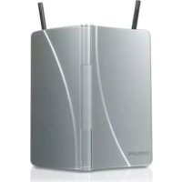
natural_image
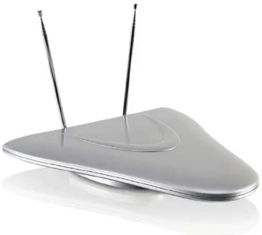
Modern silver electronic device with two antenna ports, no visible text or symbolsEN User manual
FR Mode d'emploi
For VHF/FM reception 7
For UHF reception 7
Set up a digital tuner with this antenna 8
5 Frequently asked questions 8
6 Warranty and Service 9
7 Glossary 9
1 Important
Safety
This manual contains important information about the Philips indoor television antenna. Read it carefully before you start the installation and setup.
Notice for USA
This equipment has been tested and found to comply with the limits for a Class B digital device, pursuant to part 15 of the FCC Rules. These limits are designed to provide reasonable protection against harmful interference in a residential installation. This equipment generates, uses and can radiate radio frequency energy and, if not installed and used in accordance with the instruction manual, may cause harmful interference to radio communications.
However, there is no guarantee that interference will not occur in a particular installation. If this equipment does cause harmful interference to radio or television reception, which can be determined by turning the equipment off and on, the user is encouraged to try to correct the interference by one or more of the following measures:
Relocate the receiving antenna.
Increase the separation between • equipment and receiver.
Connect the equipment into an outlet on • a circuit different from that to which the receiver is connected.
Consult the dealer or an experienced • radio/TV technician for help.
Notice for Canada
Class B Clause
This digital apparatus does not exceed the Class B limits for radio noise emissions from digital apparatus as set out in the Radio Interference Regulations of the Canadian Department of Communications.
This Class B digital apparatus complies with Canadian ICES-003.
Recycling

Your product is designed and manufactured with high quality materials and components, which can be recycled and reused.
Never dispose of your product with other household waste. Please inform yourself about the local rules on the separate collection of electrical and electronic products. The correct disposal of your old product helps prevent potentially negative consequences on the environment and human health.
The packaging of this product is intended to be recycled. Contact your local authorities for information about how to recycle the packaging.

When this logo is attached to a product, it means a financial contribution has been paid to the associated national recovery and recycling system.
© 2009 Koninklijke Philips Electronics N.V. All rights reserved. Reproduction in whole or in part is prohibited without the written consent of the copyright owner. Trademarks are the property of Koninklijke Philips Electronics N.V. or their respective owners.
2 Your SDV2790
Congratulations on your purchase and welcome to Philips!
To fully benefit from the support that Philips offers, register your product at www.philips.com/welcome.
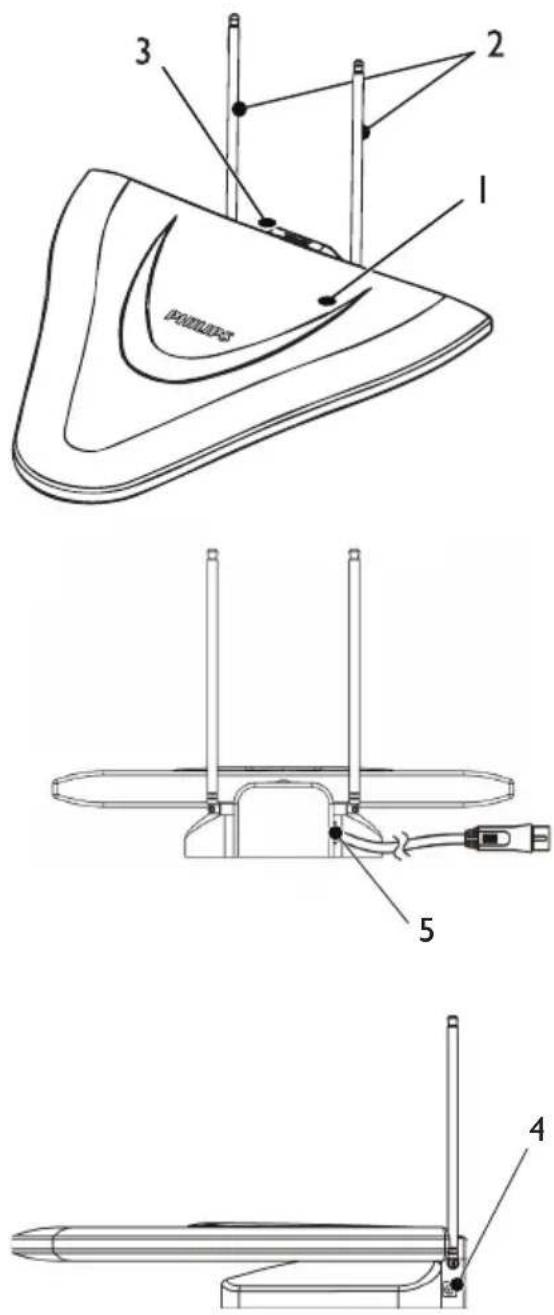
Overview
natural_image
Line drawing of a mechanical device with a coiled cable and labeled component (no text or symbols present)1 UHF log periodic antenna
2 VHF rod antenna
3 UHF/VHF gain control switch
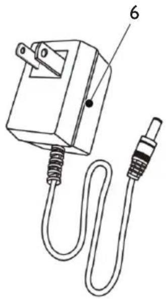
4 9V DC power connection
5 Coaxial cable (for TV connection)
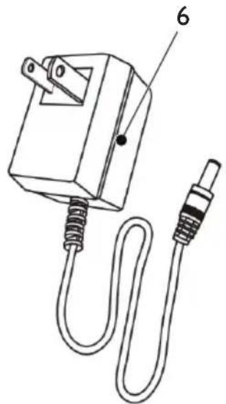
6 120V AC/9V DC power adaptor (included)
3 Get started
To ensure the antenna to work properly, read the user manual of your television before you start. Set the television so that it receives the signal from an ANTENNA instead of CABLE or SATELLITE.
Installation
Determine the signal strength
Before Installation, determine the best location for optimum reception. It is important for the antenna to have an unobstructed path to the transmitter. For best results, ensure the antenna faces the location of the transmitter.

Note
Choose a location near a window which gives the antenna a clear view of the transmitter.

Note
Place the antenna away from the metal surface to avoid interference.
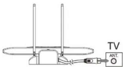
Connect to the TV
1 Connect the other end of the built-in coaxial cable to the input on the TV receiver.
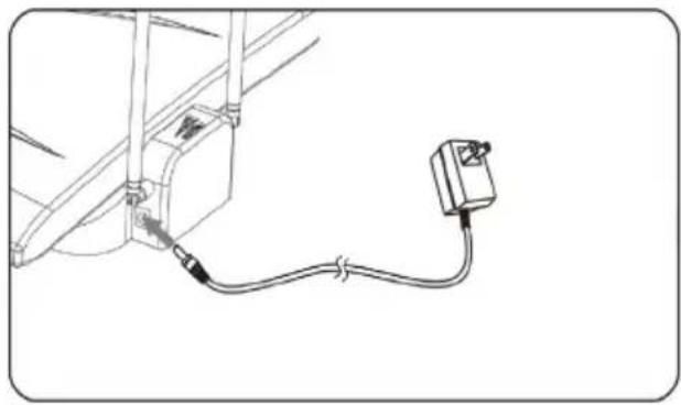
2 Connect the DC plug to the antenna and the power supply to a 120V AC outlet.
natural_image
Pure electrical circuit lines without any symbols3 Turn the power switch on.
natural_image
Simple line drawing of a triangular arch structure with a small mechanical component at the base (no text or symbols)4 Set up SDV2790
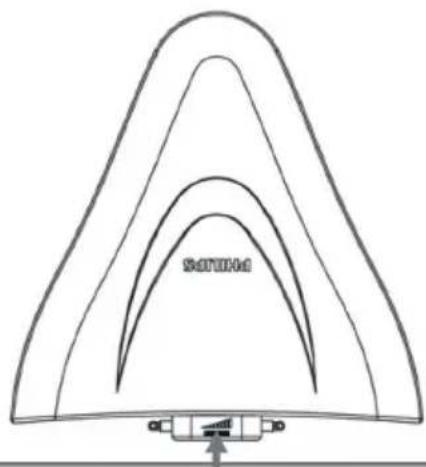
For VHF/FM reception
1 To turn the amplifier up, switch the gain control towards the max level.
natural_image
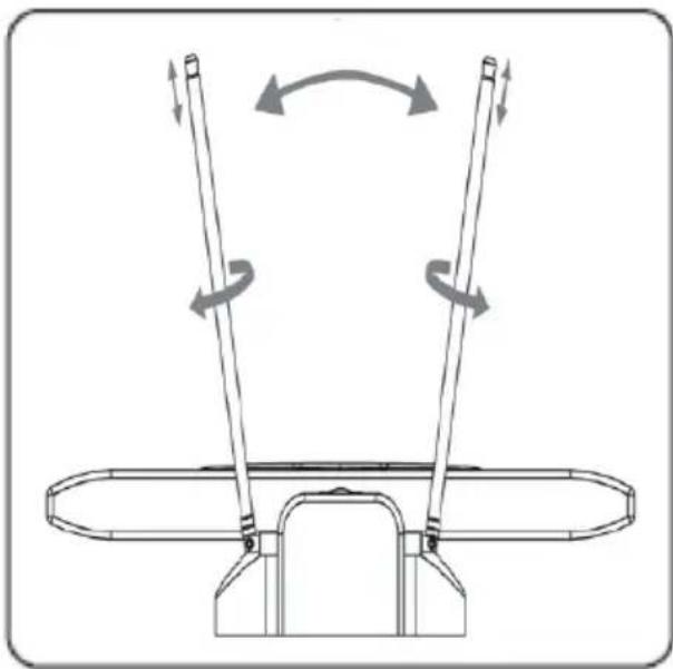
Simple line drawing of a triangular structure with curved layers and a small bracket at the base (no text or symbols)2 Extend the VHF rod antenna to the longest possible length.
3 Tum the TV or FM radio to the desired channel/station. Move the VHF rod antenna in different directions up and down until the reception is achieved.
natural_image
Technical diagram of a mechanical device with two vertical rods and rotational arrows indicating motion (no text or symbols)
Note
It is possible to switch the gain control level down for best reception.

Note
To check the distance from the local TV broadcast • transmitters to your location, visit www.antennaweb.org for more information.
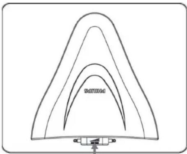
For UHF reception
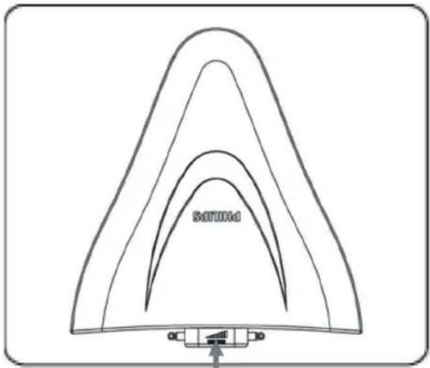
1 Turn the TV to the desired channel/ station.
2 To turn the amplifier up, switch the gain control towards the max level.
natural_image
Simple line drawing of a triangular structure with curved layers and a small connector at the base (no text or symbols)
Note
It is possible to switch the gain control level down for best reception.
Set up a digital tuner with this antenna
You can install available channels with the digital TV tuner. This automatic process is part of the setup of the tuner. Ensure the antenna has set up properly before the tuner can receive viewable channels.
There are two ways to connect the antenna to the TV:
Connect the antenna to a digital tuner. • If the signal strength is good enough, the channels can be memorized in the tuner automatically.
Connect the antenna directly to the TV. • Tune to the analogue channels and find the best antenna location. Then re-connect the antenna to the digital tuner. Ensure the signal strength is good enough before you install the channels with the tuner.
5 Frequently asked questions
Can this antenna work with Analogue transmissions?
Yes, this antenna can receive analogue television broadcasts in the UHF and VHF bandwidths.
Can this antenna receive digital or work with ATSC broadcasts?
Yes, this antenna is designed to receive ATSC and HDTV broadcasts in the UHF & VHF bandwidths.
Can the antenna be powered by a DC power supply in a boat, RV or camper?
Yes, there is a DC power socket located at the back of the antenna. Plug your cable/adapter
into the antenna and then into your power source.
Where should I place the antenna in order to get the best reception possible?
Choose a location near a window which gives the antenna a clear view of the transmitter.

Note
For best reception, place the antenna away from the metal surface to avoid interference.
How do I know how much gain (amplification) is required to receive a clear picture?
Once you have the VHF dipoles extended to the longest length, turn on the amplifier. Turn the amplifier up to the max position and then reduce as needed. In some case, you need to turn the amplifier down to receive a clearer picture.
Can I set up this antenna with a digital tuner?
Yes, this antenna can be set up with a digital tuner. (see 'Set up a digital tuner with this antenna' on page 8)
6 Warranty and Service
Limited One-Year Warranty Philips warrants that this product shall be free from defects in material, workmanship and assembly, under normal use, in accordance with the specifications and warnings, for one year from the date of your purchase of this product. This warranty extends only to the original purchaser of the product, and is not transferable. To exercise your rights under this warranty, you must provide proof of purchase in the form of an original sales receipt that shows the product name and the date of purchase. For customer support or to obtain warranty service, please call 919-573-7854. THERE ARE NO OTHER EXPRESS OR IMPLIED WARRANTIES. Philips' liability is limited to repair or, at its sole option, replacement of the product. Incidental, special and consequential damages are disclaimed where permitted by law. This warranty gives you specific legal rights. You may also have other rights that vary from state to state.
Warranty information can also be found at: www.philips.com/welcome
For technical support, send us an email with the model number of the product and a detailed description of your problem to:accessorysupport@philips.com
7 Glossary
A
Amplifier
A device, either a single stage or a large scale circuit with multiple stages for creating gain, i.e. it makes small signals larger.
Antenna
A device, such as a rod or wire, which picks up a received radio frequency signal or radiates a transmitted RF signal.
ATSC (Advanced Television Systems Committee)
The Advanced Television Systems Committee, Inc., is an international, non-profit organization developing voluntary standards for digital television. The high definition television standards defined by the ATSC produce wide screen 16:9 images up to 1920x1080 pixels in size -- more than six times the display resolution of the earlier standard. However, many different image sizes are also supported, so that up to six standard-definition “virtual channels” can be broadcast on a single 6 MHz TV channel.
C
Coaxial
A single copper conductor, surrounded with a layer of insulation, covered by a surrounding copper shield and finally, an insulating jacket. An unbalanced transmission line with constant impedance. In audio, this type is commonly used for low level, line signals terminated in RCA connectors.
F
Female connector
A female connector is a connector attached to a wire, cable, or piece of hardware, having one or more recessed holes with electrical terminals inside, and constructed in such a way that a plug with exposed conductors (male connector) can be inserted snugly into it to ensure a reliable physical and electrical connection.
FM (Frequency Modulation)
In radio broadcasting: a method of modulation in which the frequency of the carrier voltage is varied with the frequency of the modulation voltage.
H
HDTV (High-Definition Television)
It is a digital television broadcasting system with higher resolution than traditional television systems (standard-definition TV, or SDTV). HDTV is digitally broadcast; the earliest implementations used analog broadcasting, but today digital television (DTV) signals are used, requiring less bandwidth due to digital video compression.
M
Male connector
A male connector is a connector attached to a wire, cable, or piece of hardware, having one or more exposed, unshielded electrical terminals, and constructed in such a way that it can be inserted snugly into a receptacle (female connector) to ensure a reliable physical and electrical connection.
U
UHF (Ultra high frequency)
In radio or TV broadcasting: it is the frequency range of electromagnetic waves which lies between 300 MHz and 3 GHz (3000 MHz).
V
VHF (Very high frequency)
In radio or TV broadcasting: it is the frequency range of electromagnetic waves which lies between 30 MHz and 300 MHz.
Table des matières
natural_image
Line drawing of a mechanical device with a coiled cable and labeled component (no text or symbols present)natural_image
Pure electrical circuit lines without any symbolsnatural_image
Pure technical diagram of a triangular structure with internal curved lines and a base component (no text or symbols)4 Configuration de SDV2790
natural_image
Simple line drawing of a triangular structure with curved layers and a small bracket at the base (no text or symbols)natural_image
Technical line drawing of a mechanical device with two vertical rods and rotational arrows indicating motion (no text or symbols)
Remarque
natural_image
Simple line drawing of a triangular arch structure with a small labeled component at the base (no text or symbols)
Remarque
ATSC (Advanced Television Systems Committee)
FM (Frequency Modulation)
UHF (Ultra high frequency, ultrahaute fréquence)
natural_image
Line drawing of a mechanical device with a coiled cable and labeled component (no text or symbols present)natural_image
Pure electrical circuit lines without any symbolsnatural_image
Simple line drawing of a triangular arch structure with a small base and arrow, no text or symbols present.natural_image
Simple line drawing of a triangular arch structure with a small labeled component at the base (no text or symbols)natural_image
Technical line drawing of a mechanical device with two vertical rods and rotational arrows indicating motion (no text or symbols)
Nota
natural_image
Simple line drawing of a triangular arch structure with a small inset showing a device labeled 'SOTOM' (no text or symbols on the main diagram)
Nota

- Frequently asked questions 8
- Warranty and Service 9
- Glossary 9
- Important
- Safety
- Notice for USA
- Notice for Canada
- Class B Clause
- Recycling
- Your SDV2790
- Get started
- Installation
- Determine the signal strength
- Note
- Connect to the TV
- Set up SDV2790
- For VHF/FM reception
- For UHF reception
- Set up a digital tuner with this antenna
- There are two ways to connect the antenna to the TV:
- Frequently asked questions
- Warranty and Service
- Glossary
- A
- Amplifier
- Antenna
- ATSC (Advanced Television Systems Committee)
- C
- Coaxial
- F
- Female connector
- FM (Frequency Modulation)
- H
- HDTV (High-Definition Television)
- M
- Male connector
- U
- UHF (Ultra high frequency)
- V
- VHF (Very high frequency)
- Table des matières
- Configuration de SDV2790
- Remarque
- UHF (Ultra high frequency, ultrahaute fréquence)
- Nota
Brand : PHILIPS
Model : SDV2790
Category : TV Antenna