
Maui G2 - Speaker LD Systems - Free user manual and instructions
Find the device manual for free Maui G2 LD Systems in PDF.
| Brand | LD Systems |
| Model | Maui G2 |
| Category | Active column loudspeaker |
| Type | Active 2-way PA system |
| Cabinet material | Aluminum and steel |
| Available color | Black or white |
| Column connectors | SpeakON-compatible connector, screw terminal, multi-pin connector |
| Subwoofer connectors | SpeakON-compatible connector, screw terminal |
| Power supply | 230 V AC, 50-60 Hz (estimated) |
| Nominal power | 500 W RMS (estimated) |
| Key features | Wall or pole mount, adjustable tilt and orientation |
| Included accessories | Installation kits (depending on version) |
| Operating temperature | Non-tropical use, max altitude 2000 m |
| Maximum sound level | Do not exceed 90 dB SPL during prolonged use |
| Maintenance and cleaning | Use a dry cloth |
| Safety | Read the preventive measures in the manual carefully |
| Spare parts and repairability | Installation kits available separately; repair by qualified personnel |
| Manufacturer warranty | According to Adam Hall conditions (see manual) |
Frequently Asked Questions - Maui G2 LD Systems
User questions about Maui G2 LD Systems
0 question about this device. Answer the ones you know or ask your own.
Ask a new question about this device
Download the instructions for your Speaker in PDF format for free! Find your manual Maui G2 - LD Systems and take your electronic device back in hand. On this page are published all the documents necessary for the use of your device. Maui G2 by LD Systems.
USER MANUAL Maui G2 LD Systems
natural_image
Product display of black rectangular electronic devices with stands, no visible text or symbolsMAUI G2 INSTALLATION KIT
LDMG2IK1(W) PARALLEL WALL MOUNT
LDMG2IK2(W) TILT AND SWIVEL
LDMG2SPS(W) FLOOR STAND
ENGLISH
PREVENTIVE MEASURES 3-4
INTRODUCTION 4
COMPONENTS 4-5
ADAPTER FOR SPEAKER COLUMN 6
ADAPTER FOR SUBWOOFER 6
WALL MOUNTING LDMG2IK1 7
DIMENSIONS OF MOUNTING RAIL 8
WALL MOUNTING LDMG2IK2 9
DIMENSIONS OF MOUNTING PLATE 10
POSITIONING TILT & SWIVEL BRACKET 10
MOUNTING LDMG2SPS 11
TECHNICAL DATA 12-14
MANUFACTURER'S DECLARATIONS 14
DEUTSCH
We have designed this product to operate reliably over many years. LD Systems stands for this with its name and many years of experience as a manufacturer of high-quality audio products. Please read this User's Manual carefully, so that you can begin making optimum use of your LD Systems product quickly.
You can find more information about LD-SYSTEMS at our Internet site WWW.LD-SYSTEMS.COM
PREVENTIVE MEASURES
- Please read these instructions carefully.
- Keep all information and instructions in a safe place.
- Follow the instructions.
- Observe all safety warnings. Never remove safety warnings or other information from the equipment.
- Use the equipment only in the intended manner and for the intended purpose.
- Use only sufficiently stable and compatible stands and/or mounts (for fixed installations). Make certain that wall mounts are properly installed and secured. Make certain that the equipment is installed securely and cannot fall down.
- During installation, observ e the applicable safety regulations for your country.
- Never install and operate the equipment near radiators, heat registers, ovens or other sources of heat. Make certain that the equipment is always installed so that is cooled sufficiently and cannot overheat.
- Never place sources of ignition, e.g., burning candles, on the equipment.
- Ventilation slits must not be blocked.
- Do not use this equipment in the immediate vicinity of water (does not apply to special outdoor equipment - in this case, observe the special instructions noted below. Do not expose this equipment to flammable materials, fluids or gases. Avoid direct sunlight!
- Make certain that dripping or splashed water cannot enter the equipment. Do not place containers filled with liquids, such as vases or drinking vessels, on the equipment.
- Make certain that objects cannot fall into the device.
- Use this equipment only with the accessories recommended and intended by the manufacturer.
- Do not open or modify this equipment.
- After connecting the equipment, check all cables in order to prevent damage or accidents, e.g., due to tripping hazards.
- During transport, make certain that the equipment cannot fall down and possibly cause property damage and personal injuries.
- If your equipment is no longer functioning properly, if fluids or objects have gotten inside the equipment or if it has been damaged in anot her way, switch it off immediately and unplug it from the mains outlet (if it is a powered device). This equipment may only be repaired by authorized, qualified personnel.
- Clean the equipment using a dry cloth.
- Comply with all applicable disposal laws in your country. During disposal of packaging, please separate plastic and paper/cardboard.
- Plastic bags must be kept out of reach of children.
FOR EQUIPMENT THAT CONNECTS TO THE POWER MAINS
- CAUTION: If the power cord of the device is equipped with an earthing contact, then it must be connected to an outlet with a protective ground. Never deactivate the protective ground of a power cord.
- If the equipment has been exposed to strong fluctuations in temperature (for example, after transport), do not switch it on immediately. Moisture and condensation could damage the equipment. Do not switch on the equipment until it has reached room temperature.
- Before connecting the equipment to the power outlet, first verify that the mains voltage and frequency match the values specified on the equipment. If the equipment has a voltage selection switch, connect the equipment to the power outlet only if the equipment values and the mains power values match. If the included power cord or power adapter does not fit in your wall outlet, contact your electrician.
- Do not step on the power cord. Make certain that the power cable does not become kinked, especially at the mains outlet and/or power adapter and the equipment connector.
- When connecting the equipment, make certain that the power cord or power adapter is always freely accessible. Always disconnect the equipment from the power supply if the equipment is not in use or if you want to clean the equipment. Always unplug the power cord and power adapter from the power outlet at the plug or adapter and not by pulling on the cord. Never touch the power cord and power adapter with wet hands.
- Whenever possible, avoid switching the equipment on and off in quick succession because otherwise this can shorten the useful life of the equipment.
- IMPORTANT INFORMATION: Replace fuses only with fuses of the same type and rating. If a fuse blows repeatedly, please contact an authorised service centre.
- To disconnect the equipment from the power mains completely, unplug the power cord or power adapter from the power outlet.
- If your device is equipped with a Volex power connector, the mating Volex equipment connector must be unlocked before it can be removed. However, this also means that the equipment can slide and fall down if the power cable is pulled, which can lead to personal injuries and/or other damage. For this reason, always be careful when laying cables.
- Unplug the power cord and power adapter from the power outlet if there is a risk of a lightning strike or before extended periods of disuse.

CAUTION:
To reduce the risk of electric shock, do not remove cover (or back). There are no user serviceable parts inside. Maintenance and repairs should be exclusively carried out by qualified service personnel.
The warning triangle with lightning symbol indicates dangerous uninsulated voltage inside the unit, which may cause an electrical shock.

The warning triangle with exclamation mark indicates important operating and maintenance instructions.
Warning! This symbol indicates a hot surface. Certain parts of the housing can become hot during operation. After use, wait for a cool-down period of at least 10 minutes before handling or transporting the device.

Warning! This device is designed for use below 2000 metres in altitude.

Warning! This product is not intended for use in tropical climates.
CAUTION! HIGH VOLUMES IN AUDIO PRODUCTS!
This device is meant for professional use. Therefore, commercial use of this equipment is subject to the respectively applicable national accident prevention rules and regulations. As a manufacturer, Adam Hall is obligated to notify you formally about the existence of potential health risks.
Hearing damage due to high volume and prolonged exposure: When in use, this product is capable of producing high sound-pressure levels (SPL) that can lead to irreversible hearing damage in performers, employees, and audience members. For this reason, avoid prolonged exposure to volumes in excess of 90 dB.
NOTE: This equipment has been tested and found to comply with the limits for a Class B digital device, pursuant to Part 15 of the FCC Rules. These limits are designed to provide reasonable protection against harmful interference in a residential installation. This equipment generates, uses and can radiate radio frequency energy and, if not installed and used in accordance with the instructions, may cause harmful interference to radio communications. However, there is no guarantee that interference will not occur in a particular installation. If this equipment does cause harmful interference to radio or television reception, which can be determined by turning the equipment off and on, the user is encouraged to try to correct the interference by one or more of the following measures:
- Reorient or relocate the receiving antenna.
- Increase the separation between the equipment and receiver.
- Connect the equipment into an outlet on a circuit different from that to which the receiver is connected.
- Consult the dealer or an experienced radio/TV technician for help.
INTRODUCTION
The mounting kits for the MAUI G2 series speaker columns facilitate elegant, discreet and flexible installation. The set includes two adapters with speakON-compatible sockets, terminal block connections and multi-pin sockets for connecting the column to the subwoofer. All sets are available in black or white.
IMPORTANT: In the event of separate mounting, always take care to ensure that both pillar elements are used and never only the upper pillar element. Otherwise, the automatic detection function will not work correctly and the system can potentially suffer damage.
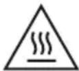
COMPONENTS
Installation kit for parallel wall mounting of MAUI 11 G2 and MAUI 28 G2 speaker columns
LDMG2IK1 (black)
LDMG2IK1W (white)
- Adapter for connecting to the speaker column (with speakON-compatible connection and terminal block connections)
- Adapter for connecting to the MAUI G2 subwoofer (with speakON-compatible connection and terminal block connections)
- Mounting rail for vertical mounting on a wall
- Hanging bracket for attaching to the speaker column
(1 x set of screws for attaching the hanging bracket to the speaker column and 1 x locking screw included. Tools required: 3 mm and 4 mm Allen keys or internal hex socket)
natural_image
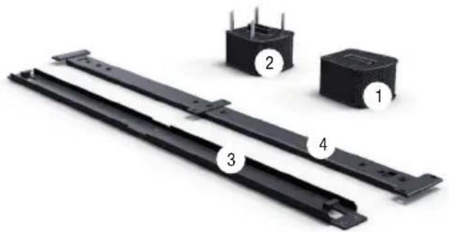
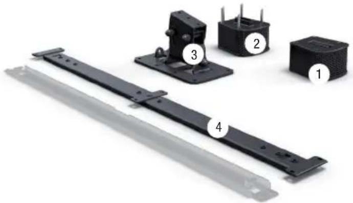
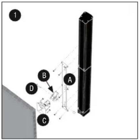
Exterior view of four electronic components with numbered labels (1, 2, 3, 4) showing structural details (no text or symbols beyond labels)Installation kit with tilt and swivel mechanism for wall mounting the MAUI 11 G2 and MAUI 28 G2 speaker columns
LDMG2IK2 (black)
LDMG2IK2W (white)
- Adapter for connecting to the speaker column (with speakON-compatible connection and terminal block connections)
- Adapter for connecting to the MAUI G2 subwoofer (with speakON-compatible connection and terminal block connections)
- Tilt and swivel bracket for vertical wall mounting
- Mounting bracket for attaching to the speakers column (the mounting rail is greyed out in the picture. It is included for logistical reasons, but is not required for this type of installation)
(1 x set of screws for attaching the hanging bracket to the speaker column and the tilt and swivel bracket to the hanging bracket included.
Tools required: 3 mm and 4 mm Allen keys or internal hex socket)
natural_image
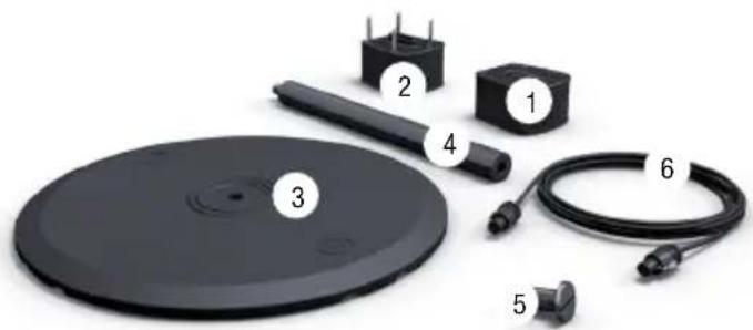
Exploded view of four electronic components (labeled 1 to 4) shown in a black plastic assembly with mounting brackets and a metal bracket (no text or symbols beyond labels)Floor stand kit for MAUI 11 G2 and MAUI 28 G2 speaker columns
LDMG2SPS (black)
LDMG2SPSW (white)
- Adapter for connecting to the speaker column (with speakON-compatible connection and terminal block connections)
- Adapter for connecting to the MAUI G2 subwoofer (with speakON-compatible connection and terminal block connections)
- Cast iron base for attaching to the rod attachment or the column adapter
- Rod attachment (height 55 cm) with M20 threaded bolt at the upper end and M20 thread at the lower end
- M20 bolt for connecting the rod attachment or the column adapter to the cast iron base
- 4-wire connection cable with speakON-compatible connectors
(tools required: large flat screwdriver, 3 mm Allen key or hex socket)
natural_image
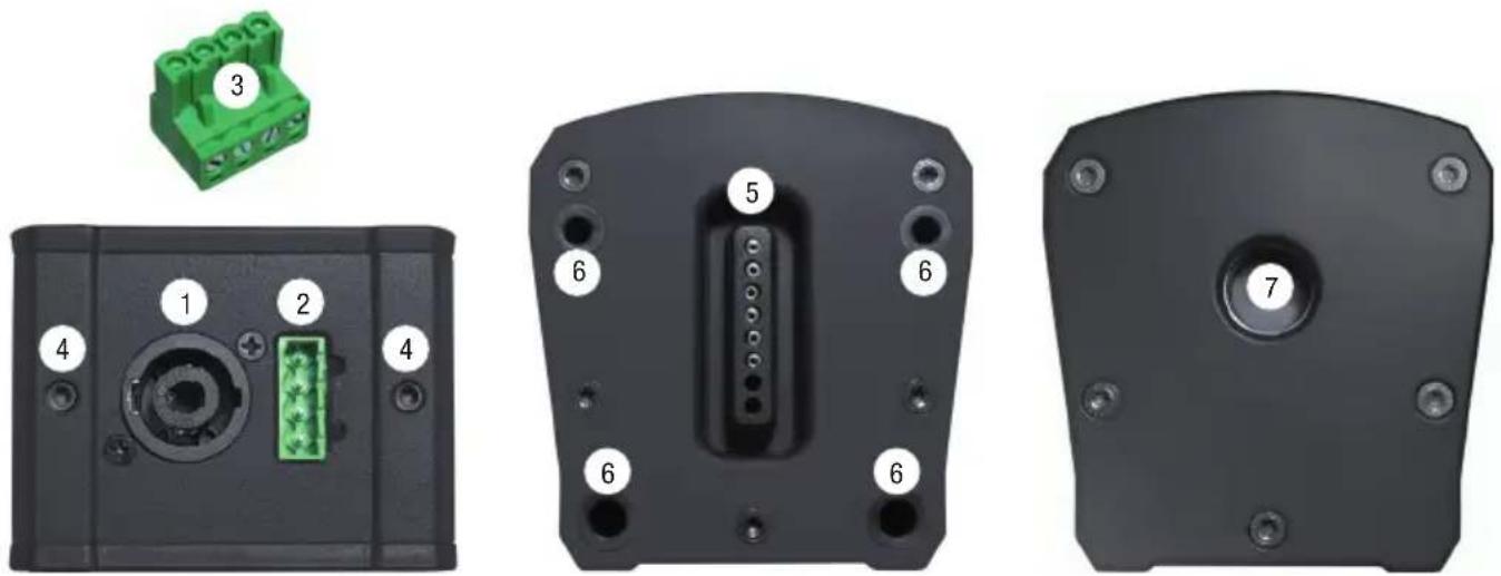
Product photo of a black electronic device with numbered components including a circular base, cable, and terminal blocks (no text or symbols visible)ADAPTER FOR SPEAKER COLUMN
- speakON-compatible connector for connecting the column adapter to the subwoofer adapter The speakON-compatible connector is wired in parallel with the terminal block connector (2).
- Terminal block connector for connecting the column adapter to the subwoofer adapter The terminal block connector is wired in parallel with the speakON-compatible connector (1).
- Terminal block connector, 4-pole
- Threaded grub screw (3mm hex) to lock the rear steel bolt after attaching to the speaker column
- Multipin connector for sending speaker signal to the speaker column
- Rubberised guide holes for correct assembly and firm grip on the speaker column
- M20 thread for connecting the column adapter to the rod attachment or the base
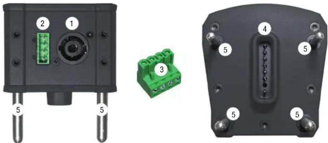
ADAPTER FOR SUBWOOFER
- speakON-compatible connector for connecting the subwoofer adapter to the column adapter The speakON-compatible connector is wired in parallel with the terminal block connector (2).
- Terminal block connector for connecting the subwoofer adapter to the column adapter The terminal block connector is wired in parallel with the speakON-compatible connector (1).
- Terminal block connector, 4 pole
- Multipin connector for sending speaker signal to the speaker column
- Steel guide pins for correct assembly and firm grip on the subwoofer
natural_image
Three views of a black electronic device showing internal components: top view with green connector, side view with green connector, and front view with labeled pins (no text or symbols beyond component numbers)WALL MOUNTING LDMG2IK1
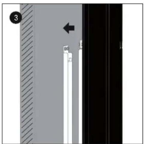
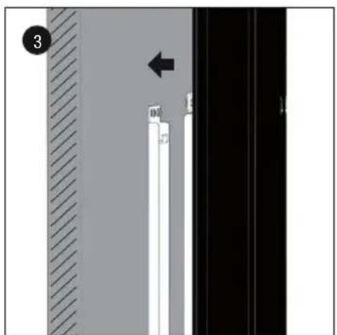
- Attach the two supplied terminal block connectors to a 4-core speaker cable (4 x 1.5 mm²), ensuring that they are wired in parallel (see printed configuration on adapter) and plug the connectors into the designated column and subwoofer terminals on the adapters. Now, from underneath, push the adapter with the 4 rubberised holes on to the speaker column as far as it will go (slightly loosen the 3 mm hexagonal grub screw if necessary) and secure to the adapter using the two grub screws. The electrical contact for the signal supply to the speaker column will be automatically established.
- Using screws, attach mounting rail A in a suitable position to a solid wall, with its flat side and with the tabs facing upwards (6 screws, "THIS S IDE UP" facing upwards). Use suitable screws and plugs etc. to ensure secure mounting. Remove the 6 grub screws (3 mm hexagonal socket) from the appropriate locations on the rear of the speaker column and attach the flat side of the mounting bracket B to the MAUI G2 speaker column using the supplied bolts (M5 x 10 mm, 4 mm hexagonal socket). Observe the instruction "THIS SIDE UP" on the mounting bracket.
-
-
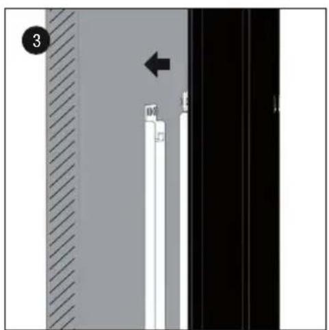
- Now slide the speaker column with the mounting bracket rail into the mounting rail on the wall in such a way that the retaining tabs on the mounting rail slot into the recesses of the mounting bracket, and then push the column downwards into its fixed location (approx. 10 mm).
-
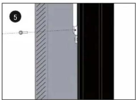
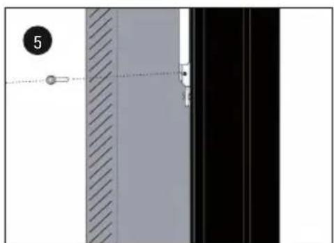
- Secure installation with the supplied locking screw (M4, 3 mm hexagonal socket). The corresponding thread is located at the base of the speaker column mounting bracket.
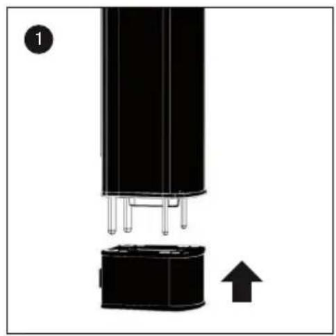
- From above, now push the adapter with the steel pins onto the subwoofer as far as it will go.
natural_image
Close-up of a black cylindrical electronic component with pins and an attached base, showing a directional arrow (no text or symbols)
natural_image
Diagram showing a vertical structure with white and black panels, a hatched wall, and an arrow pointing to a specific section (no text or symbols present)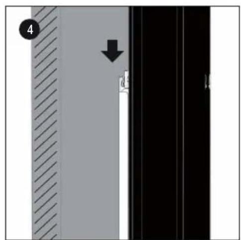
natural_image
Diagram showing a vertical panel with diagonal hatching and a dashed line, alongside a black panel with a small object at the end (no text or symbols)
WALL MOUNTING LDMG2IK2
- Remove the 6 grub screws (3 mm hexagonal socket) from the appropriate locations on the rear of the speaker column and attach the flat side of mounting bracket A to the MAUI G2 speaker column using the supplied bolts (M5 x 10 mm, 4 mm hexagonal socket). Observe the instruction "THIS SIDE UP" on the mounting bracket (this side facing upwards).
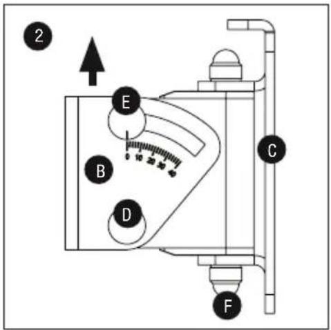
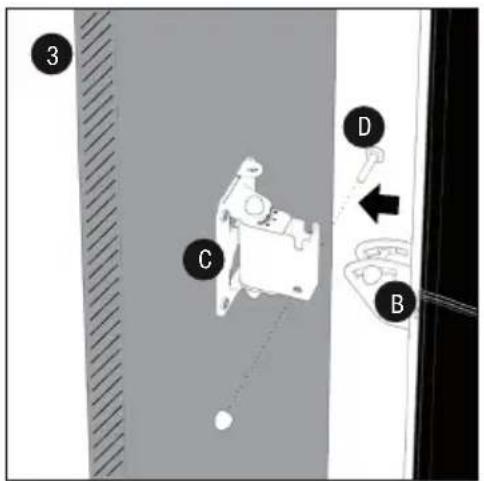
- Slightly loosen bolt E (do not remove), loosen and remove bolt D from the tilt & swivel arm, remove and lift the U-bracket B from its mounting. Firmly attach U-bracket B in the desired position on mounting bracket A with the 3 supplied screws (M5 x 10 mm, 4 mm hex socket) (for maximum tilt, use the lowest of the 3 positions – MAUI 11 G2 = max. 22°, MAUI 28 G2 = max. 12°).
Using screws, attach mounting plate C vertically in a suitable position to a solid wall with its flat side and safety eyelet facing upwards (6 screws). Use suitable screws and plugs etc. to ensure secure mounting.
Now attach the two supplied terminal block connectors to a 4-core speaker cable (4 x 1.5 mm ^2 ), ensuring that they are wired in parallel (see printed configuration on adapter) and plug the connectors into the designated column and subwoofer terminals on the adapters. Now, from underneath, push the adapter with the 4 rubberised holes on to the speaker column as far as it will go (slightly loosen the 3 mm hexagonal grub screw if necessary) and secure to the adapter using the two grub screws. The electrical contact for the signal supply to the speaker column will be automatically established. - Now slide the speaker column with the attached U-bracket B into the bracket on the wall, reinstall bolt D into its designated position and secure it with the previously removed nut.
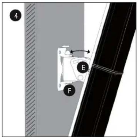
- The speaker column can be tilted vertically by slightly loosening nut E, adjusting to the desired angle and then re-tightening the nut. The column can be adjusted horizontally by loosening nut F (remove plastic cap beforehand), adjusting the angle as required, and then re-tightening the nut.
- From above, now push the adapter with the steel pins onto the subwoofer as far as it will go.
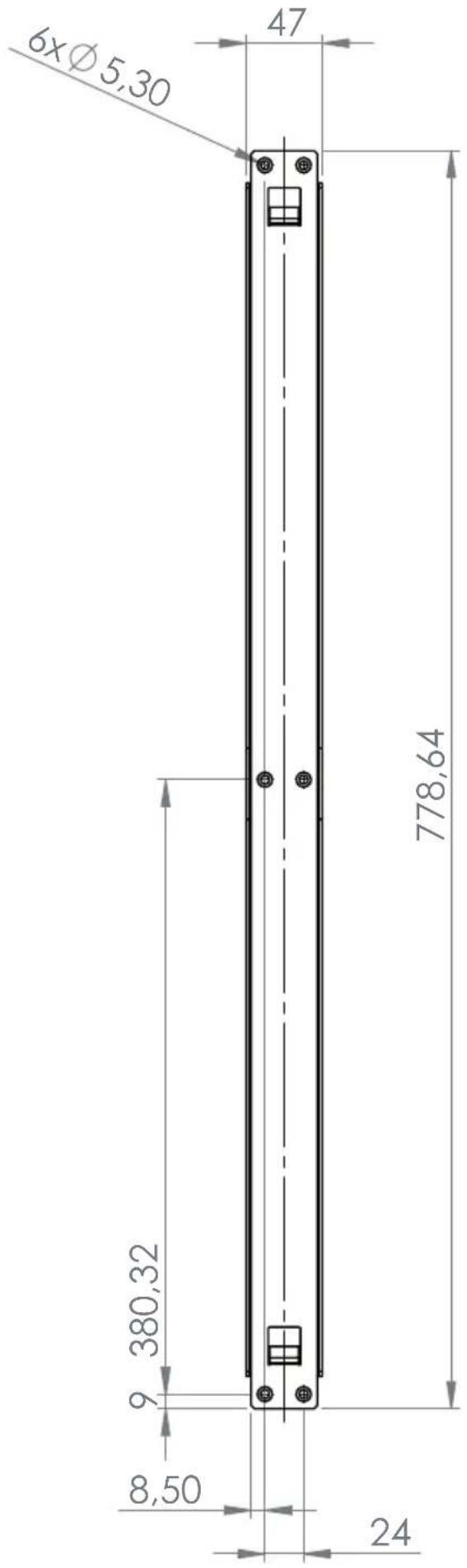
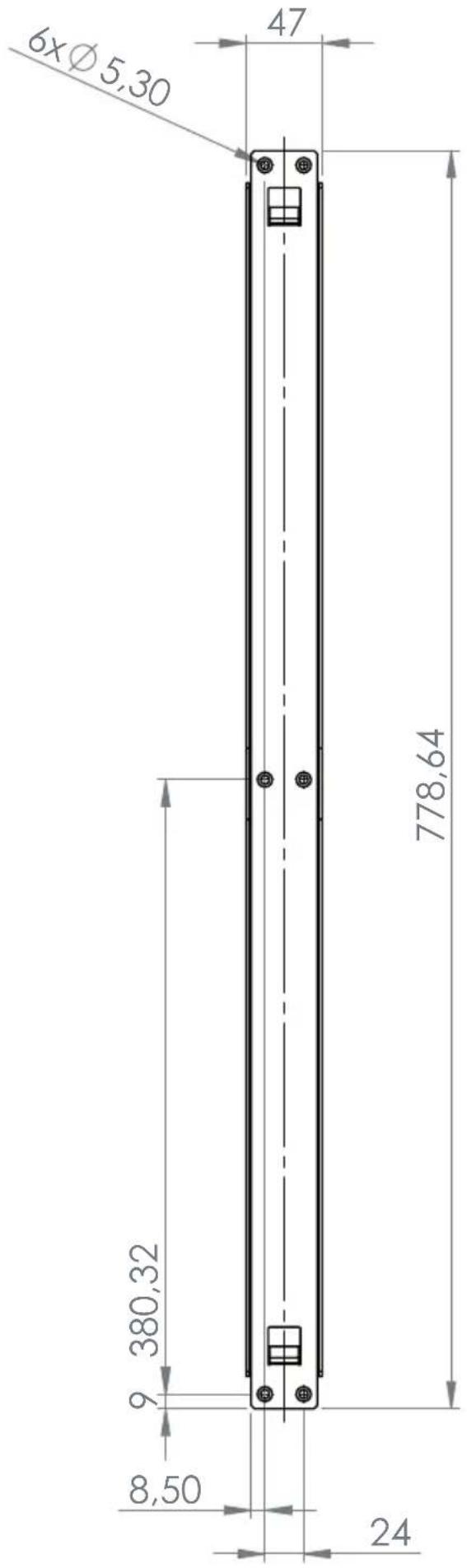
DIMENSIONS OF MOUNTING PLATE
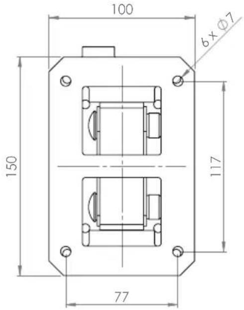
POSITIONING TILT & SWIVEL BRACKET
The tilt and swivel U-bracket can be installed in 3 different positions on the speaker column mounting bracket. In its lowest position, the system provides a maximum tilt angle of 22^ for the MAUI 11 G2 and 12^ for the MAUI 28 8G2 speaker columns.
natural_image
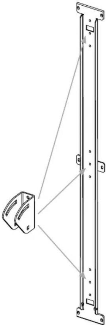
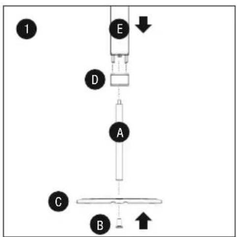
Technical line drawing of a mechanical assembly with a bracket and vertical rail (no text or symbols)MOUNTING LDMG2SPS
There are two ways to attach the MAUI G2 speaker column to the base.
- Installation with the 55 mm rod attachment.
Attach the rod attachment to base C with M20 special screw B, ensuring a firm grip. Screw adapter D (with M20 thread) onto the rod attachment as far as it will go. Now attach speaker column E flush to the adapter (slightly loosen the 3 mm hexagonal grub screws if necessary). Steel guide pins facilitate correct assembly and at the same time ensure a secure hold. The electrical contact for the signal supply to the speaker column will be automatically established. Now attach the adapter flush to the subwoofer with the 4 steel pins and connect both adapters using the supplied speaker cable (4-core with speakON-compatible connectors).
- Direct attachment to the base, without rod attachment.
Attach adapter D (with M20 thread) to base C with M20 special screw B, ensuring a firm grip. Now attach speaker column E flush to the adapter (slightly loosen the 3 mm hexagonal grub screws if necessary). Steel guide pins facilitate correct assembly and at the same time ensure a secure hold. The electrical contact for the signal supply to the speaker column will be automatically established. Now attach the adapter flush to the subwoofer with the 4 steel pins and connect both adapters using the supplied speaker cable (4-core with speakON-compatible connectors).
flowchart
graph TD
    A["A"] --> B["B"]
    B --> C["C"]
    C --> D["D"]
    D --> E["E"]
    E --> F["1"]
    style A fill:#f9f,stroke:#333
    style B fill:#ccf,stroke:#333
    style C fill:#cfc,stroke:#333
    style D fill:#fcc,stroke:#333
    style E fill:#cff,stroke:#333

TECHNICAL DATA
Model name: LDMG2IK1 LDMG2IK1W
| Type: PA Loudspeaker Accessories PA Loudspeaker Accessories | ||
| Part: Wall Mount Bracket Wall Mount Bracket | ||
| Material: Steel Steel | ||
| Surface: Powder Coated Powder Coated | ||
| Colour: Black | White | |
| Max. Load | 12Kg | 12Kg |
| Dimensions (W x H x D): | 75mm x 810mm x 15mm | 75mm x 810mm x 15mm |
| Weight: | 1.5Kg | 1.5Kg |
| Part: Column Adapter | Column Adapter | |
| Features: | Speakon Compatible, Terminal Block Connection,M20 Thread | Speakon Compatible, Terminal Block Connection,M20 Thread |
| Material: Aluminium | Aluminium | |
| Surface: Powder Coated Powder Coated | ||
| Colour: Black | White | |
| Dimensions (W x H x D): | 100mm x 65mm x 105mm | 100mm x 65mm x 105mm |
| Weight: | 0.7Kg | 0.7Kg |
| Part: Subwoofer Adapter | Subwoofer Adapter | |
| Features: | Speakon Compatible, Terminal Block Connection | Speakon Compatible, Terminal Block Connection |
| Material: Aluminium | Aluminium | |
| Surface: Powder Coated Powder Coated | ||
| Colour: Black | White | |
| Dimensions (W x H x D): | 100mm x 105mm x 105mm | 100mm x 105mm x 105mm |
| Weight: | 0.5Kg | 0.5Kg |
| Part: Terminal Block Connector Terminal Block Connector | ||
| Colour: Green | Green | |
| Feature: | 4 pole | 4 pole |
| Quantity: | 2 pcs. | 2 pcs. |
Model name: LDMG2IK2 LDMG2IK2W
| Type: PA Loudspeaker Accessories PA Loudspeaker Accessories | ||
| Part: Wall Mount Bracket Wall Mount Bracket | ||
| Material: Steel Steel | ||
| Surface: Powder Coated Powder Coated | ||
| Colour: Black | White | |
| Max. Load | 12Kg | 12Kg |
| Dimensions (W x H x D): | 75mm x 810mm x 135mm | 75mm x 810mm x 135mm |
| Weight: | 2.6Kg | 2.6Kg |
| Part: Column Adapter | Column Adapter | |
| Features: | Speakon Compatible, Terminal Block Connection,M20 Thread | Speakon Compatible, Terminal Block Connection,M20 Thread |
| Material: Aluminium | Aluminium | |
| Surface: Powder Coated Powder Coated | ||
| Colour: Black | White | |
| Dimensions (W x H x D): | 100mm x 65mm x 105mm | 100mm x 65mm x 105mm |
| Weight: | 0.7Kg | 0.7Kg |
| Part: Subwoofer Adapter | Subwoofer Adapter | |
| Features: | Speakon Compatible, Terminal Block Connection | Speakon Compatible, Terminal Block Connection |
| Material: Aluminium Aluminium | |
| Surface: Powder Coated Powder Coated | |
| Colour: Black White | |
| Dimensions (W x H x D): 100mm x 105mm x 105mm 100mm x 105mm x 105mm | |
| Weight: 0.5Kg 0.5Kg | |
| Part: Terminal Block Connector Terminal Block Connector | |
| Colour: Green Green | |
| Feature: 4 pole | 4 pole |
| Quantity: 2 pcs. | |
| Model name: | LDMG2SPS | LDMG2SPSW | |
| Type: | PA Loudspeaker Accessories | PA Loudspeaker Accessories | |
| Part: Pole | Pole | ||
| Material: Steel | Steel | ||
| Surface: Powder Coated Powder Coated | |||
| Colour: Black White | |||
| Length: 500mm | 500mm | ||
| Weight: 1Kg | 1Kg | ||
| Part: Base Plate | Column Adapter | ||
| Material: Aluminium Aluminium | |||
| Surface: Powder Coated Powder Coated | |||
| Colour: Black White | |||
| Diameter: | 450mm | 450mm | |
| Weight: 9Kg | 9Kg | ||
| Part: Column Adapter | Column Adapter | ||
| Features: | Speakon Compatible, Terminal Block Connection, M20 Thread | Speakon Compatible, Terminal Block Connection, M20 Thread | |
| Material: Aluminium Aluminium | |||
| Surface: Powder Coated Powder Coated | |||
| Colour: Black White | |||
| Dimensions (W x H x D): 100mm x 65mm x 105mm | 100mm x 65mm x 105mm | ||
| Weight: 0.7Kg 0.7Kg | |||
| Part: Subwoofer Adapter | Subwoofer Adapter | ||
| Features: | Speakon Compatible, Terminal Block Connection | Speakon Compatible, Terminal Block Connection | |
| Material: Aluminium Aluminium | |||
| Surface: Powder Coated Powder Coated | |||
| Colour: Black White | |||
| Dimensions (W x H x D): 100mm x 105mm x 105mm 100mm x 105mm x 105mm | |||
| Weight: 0.5Kg 0.5Kg | |||
| Part: Speaker Cable | Speaker Cable | ||
| Connectors: | Speakon Compatible | Speakon Compatible | |
| Colour: Black Black | |||
| Length: 5m | 5m | ||
| Weight: 0.9Kg 0.9Kg | |||
| Part: Terminal Block Connector Terminal Block Connector | |||
| Colour: Green Green | |||
| Feature: 4 pole | 4 pole | ||
| Quantity: | 2 pcs. | 2 pcs. | |
MANUFACTURER'S DECLARATIONS
MANUFACTURER'S WARRANTY & LIMITATIONS OF LIABILITY
You can find our current warranty conditions and limitations of liability at: http://www.adamhall.com/media/shop/downloads/documents/manufacturersdeclarations.pdf. To request warranty service for a product, please contact Adam Hall GmbH, Daimler Straße 9, 61267 Neu Anspach / Email: Info@adamhall.com / +49 (0)6081 / 9419-0.

CORRECT DISPOSAL OF THIS PRODUCT
(valid in the European Union and other European countries with a differentiated waste collection system)
This symbol on the product, or on its documents indicates that the device may not be treated as household waste. This is to avoid environmental damage or personal injury due to uncontrolled waste disposal. Please dispose of this product separately from other waste and have it recycled to promote sustainable economic activity. Household users should contact either the retailer where they purchased this product, or their local government office, for details on where and how they can recycle this item in an environmentally friendly manner. Business users should contact their supplier and check the terms and conditions of the purchase contract. This product should not be mixed with other commercial waste for disposal.
FCC STATEMENT
This device complies with Part 15 of the FCC Rules. Operation is subject to the following two conditions:
(1) This device may not cause harmful interference, and
(2) This device must accept any interference received, including interference that may cause undesired operation
CE Compliance
Adam Hall GmbH states that this product meets the following guidelines (where applicable):
R&TTE (1999/5/EC) or RED (2014/53/EU) from June 2017
Low voltage directive (2014/35/EU)
EMV directive (2014/30/EU)
RoHS (2011/65/EU)
The complete declaration of conformity can be found at www.adamhall.com.
Furthermore, you may also direct your enquiry to info@adamhall.com.
DEUTSCH
natural_image
Exterior view of four electronic components with numbered labels (1, 2, 3, 4) showing structural parts without any text or symbols.natural_image
Exploded view of a black plastic electronic component assembly with numbered parts (1, 2, 3, 4), no visible text or symbols beyond labels.natural_image
Product photo of a black electronic device with numbered components and wiring (no visible text or symbols)ADAPTER FÜR LAUTSPRECHERSÄULE
ADAPTER FÜR SUBWOOFER
WANDMONTAGE LDMG2IK1
natural_image
Close-up of a black cylindrical electronic component with three pins and an arrow pointing to it, no visible text or symbols.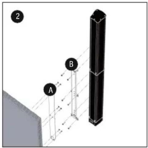

natural_image
Diagram showing a vertical structure with white and black panels, a hatched wall, and an arrow pointing to a specific section (no text or symbols present)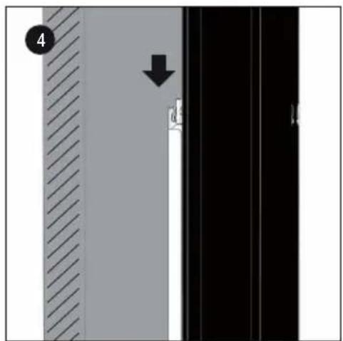
natural_image
Diagram showing a vertical panel with diagonal hatching and a downward arrow, next to a black panel with white and black sections (no text or symbols)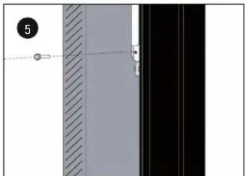
natural_image
Exterior view of a door panel with diagonal hatching and a dashed line indicating alignment (no text or symbols)ABMESSUNGEN MONTAGESCHIENE

WANDMONTAGE LDMG2IK2
natural_image
Technical line drawing of a mechanical assembly with a bracket and vertical rail (no text or symbols)MONTAGE LDMG2SPS
APPAREILS RELIÉS AU SECTEUR
natural_image
Exterior view of four electronic components with numbered labels (1, 2, 3, 4) showing structural parts (no text or symbols beyond labels)natural_image
Exploded view of a black plastic electronic component assembly with numbered parts (1, 2, 3, 4), no visible text or symbols beyond labels.natural_image
Product photo of a black electronic device with numbered components including a disc, plug, cable, and connector (no text or symbols visible)ADAPTATEUR POUR LA COLONNE D'ENCEINTES
ADAPTATEUR POUR LE CAISSON DE BASSES
MONTAGE MURAL DU LDMG2IK1
natural_image
Diagram of a cylindrical device with three pins and an attached base, showing a directional arrow (no text or symbols)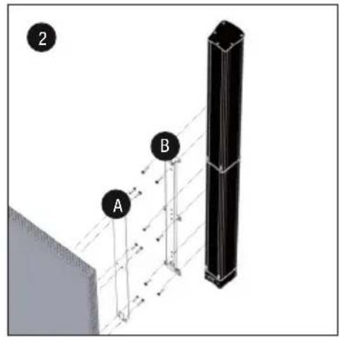
natural_image
Diagram showing a vertical structure with white and black panels, a hatched wall, and an arrow pointing to a specific section (no text or symbols present)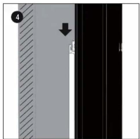
natural_image
Diagram showing a vertical panel with diagonal hatching and a downward arrow, next to a black panel with white and black sections (no text or symbols)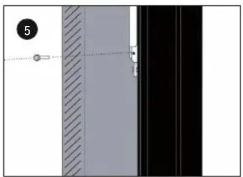
natural_image
Diagram showing a vertical panel with diagonal hatching and a black panel with a dashed line, no text or symbols present.DIMENSIONS DU RAIL DE MONTAGE

MONTAGE MURAL DU LDMG2IK2
natural_image
Technical line drawing of a mechanical assembly with a bracket and vertical rail (no text or symbols)MONTAGE DU LDMG2SPS
Type : Support mural Support mural
Type : Support mural Support mural
(Valid in the European Union and other European countries with waste separation)
natural_image
Exterior view of four electronic components with numbered labels (1, 2, 3, 4) showing structural parts (no text or symbols beyond labels)natural_image
Exploded view of a black plastic electronic component assembly with numbered parts (1, 2, 3, 4), no visible text or symbols beyond labels.natural_image
Product photo of a black electronic device with labeled parts including a circular base, plug, cable, and connector (no text or symbols visible)ADAPTADOR PARA COLUMNNA DE ALTAVOCES
ADAPTADOR PARA SUBWOOFER
MONTAJE MURAL LDMG2IK1
natural_image
Diagram of a capacitor with an arrow indicating upward movement, no text or symbols present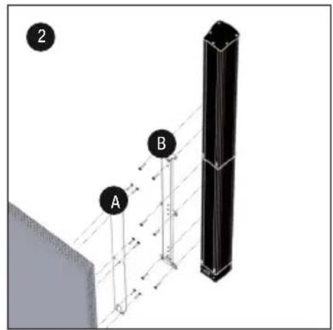
natural_image
Diagram showing a vertical structure with white and black panels, a hatched wall, and an arrow pointing to a specific section (no text or symbols present)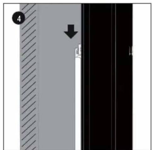
natural_image
Diagram showing a vertical panel with diagonal hatching and a black arrow pointing to a vertical line, no text or symbols present.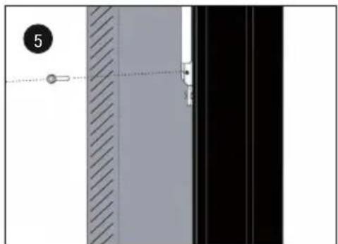
natural_image
Diagram showing a vertical panel with hatched and solid surfaces, connected by a dashed line to a black panel (no text or symbols)DIMENSIONES DEL RIEL DE MONTAJE
MONTAJE MURAL LDMG2IK2
natural_image
Technical line drawing of a mechanical assembly with a bracket and vertical rail (no text or symbols)MONTAJE LDMG2SPS
natural_image
Exterior view of four electronic components with numbered labels (1, 2, 3, 4) showing structural details (no text or symbols beyond labels)natural_image
Exploded view of a black plastic electronic component assembly with numbered parts (1, 2, 3, 4), no visible text or symbols beyond labels.natural_image
Product photo of electronic components including a circular disc, power plug, and cable with numbered labels (1-6), no visible text or symbols beyond labels.ADAPTER DO KOLUMNY GŁOŚNIKOWEJ
ADAPTER DO SUBWOOFERA
MONTAŻ ŚCIENNY LDMG2IK1
natural_image
Close-up of a black cylindrical electronic component with pins and an attached base, showing a directional arrow (no text or symbols)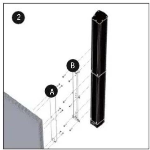

natural_image
Diagram showing a vertical structure with arrows indicating direction, no readable text or symbols present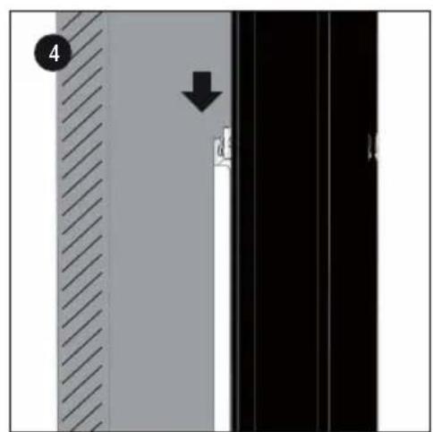
natural_image
Diagram showing a vertical panel with diagonal hatching and a downward arrow, next to a black panel with white and black sections (no text or symbols)
natural_image
Diagram showing a vertical panel with diagonal hatching and a dashed line, alongside a black panel with a small mark (no text or symbols)WYMIARY SZYNY MONTAŻOWEJ
MONTAŻ ŚCIENNY LDMG2IK2
natural_image
Technical line drawing of a mechanical assembly with a bracket and vertical rail (no text or symbols)MONTAŻ LDMG2SPS
natural_image
Exterior view of four electronic components with numbered labels (1, 2, 3, 4) showing structural parts without any text or symbols.natural_image
Exploded view of four electronic components (no text or symbols visible)natural_image
Product photo of a black electronic device with numbered components including a circular base, four labeled parts, and a coiled cable (no text or symbols visible)ADATTATORE PER COLONNA DEGLI ALTOPARLANTI
ADATTATORE PER SUBWOOFER
MONTAGGIO A PARETE LDMG2IK1
natural_image
Close-up of a black cylindrical electronic component with three pins and an arrow pointing to it, no visible text or symbols.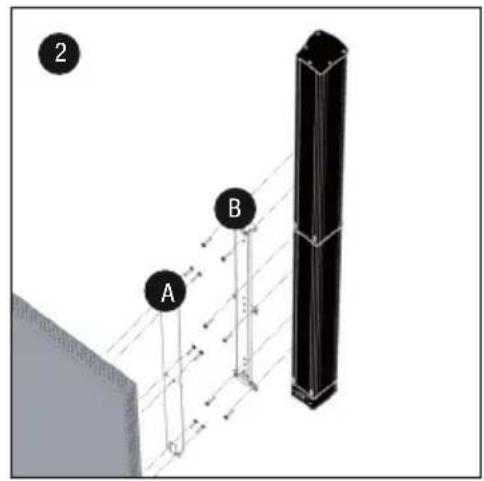

natural_image
Diagram showing a vertical structure with white and black panels, a hatched wall, and an arrow pointing to a specific section (no text or symbols present)
natural_image
Exterior view of a door panel with diagonal hatching and a hanging weight, no text or symbols visiblenatural_image
Technical line drawing of a mechanical assembly with a bracket and vertical rail (no text or symbols)MONTAGGIO LDMG2SPS
Dimensioni (L x H x P): 100mm x 65mm x 105mm 100mm x 65mm x 105mm
Peso: 0,7 kg 0,7 kg
Dimensioni (L x H x P): 100mm x 105mm x 105mm 100mm x 105mm x 105mm
Peso: 0,5 kg 0,5 kg
Dimensioni (L x H x P): 100mm x 105mm x 105mm 100mm x 105mm x 105mm
Peso: 0,5 kg 0,5 kg


- MAUI G2 INSTALLATION KIT
- ENGLISH
- DEUTSCH
- PREVENTIVE MEASURES
- FOR EQUIPMENT THAT CONNECTS TO THE POWER MAINS
- CAUTION:
- CAUTION! HIGH VOLUMES IN AUDIO PRODUCTS!
- INTRODUCTION
- COMPONENTS
- Installation kit for parallel wall mounting of MAUI 11 G2 and MAUI 28 G2 speaker columns
- Installation kit with tilt and swivel mechanism for wall mounting the MAUI 11 G2 and MAUI 28 G2 speaker columns
- Floor stand kit for MAUI 11 G2 and MAUI 28 G2 speaker columns
- ADAPTER FOR SPEAKER COLUMN
- ADAPTER FOR SUBWOOFER
- WALL MOUNTING LDMG2IK1
- WALL MOUNTING LDMG2IK2
- DIMENSIONS OF MOUNTING PLATE
- POSITIONING TILT & SWIVEL BRACKET
- MOUNTING LDMG2SPS
- TECHNICAL DATA
- MANUFACTURER'S DECLARATIONS
- MANUFACTURER'S WARRANTY & LIMITATIONS OF LIABILITY
- CORRECT DISPOSAL OF THIS PRODUCT
- FCC STATEMENT
- CE Compliance
- ADAPTER FÜR LAUTSPRECHERSÄULE
- ADAPTER FÜR SUBWOOFER
- WANDMONTAGE LDMG2IK1
- ABMESSUNGEN MONTAGESCHIENE
- WANDMONTAGE LDMG2IK2
- MONTAGE LDMG2SPS
- APPAREILS RELIÉS AU SECTEUR
- ADAPTATEUR POUR LA COLONNE D'ENCEINTES
- ADAPTATEUR POUR LE CAISSON DE BASSES
- MONTAGE MURAL DU LDMG2IK1
- DIMENSIONS DU RAIL DE MONTAGE
- MONTAGE MURAL DU LDMG2IK2
- MONTAGE DU LDMG2SPS
- ADAPTADOR PARA COLUMNNA DE ALTAVOCES
- ADAPTADOR PARA SUBWOOFER
- MONTAJE MURAL LDMG2IK1
- DIMENSIONES DEL RIEL DE MONTAJE
- MONTAJE MURAL LDMG2IK2
- MONTAJE LDMG2SPS
- ADAPTER DO KOLUMNY GŁOŚNIKOWEJ
- ADAPTER DO SUBWOOFERA
- MONTAŻ ŚCIENNY LDMG2IK1
- WYMIARY SZYNY MONTAŻOWEJ
- MONTAŻ ŚCIENNY LDMG2IK2
- MONTAŻ LDMG2SPS
- ADATTATORE PER COLONNA DEGLI ALTOPARLANTI
- ADATTATORE PER SUBWOOFER
- MONTAGGIO A PARETE LDMG2IK1
- MONTAGGIO LDMG2SPS
Brand : LD Systems
Model : Maui G2
Category : Speaker