S1000R - Uninterruptible power supply Middle Atlantic - Free user manual and instructions
Find the device manual for free S1000R Middle Atlantic in PDF.
| Product type | Uninterruptible Power Supply (UPS) |
| Brand | Middle Atlantic |
| Model | S1000R |
| VA capacity | 1000 VA |
| Input voltage | 120 V AC |
| Output voltage | 120 V AC regulated (AVR) |
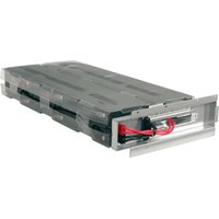
| Battery type | Sealed lead-acid, 24 V, 16 Ah max |
| Protection | Surge suppressor, EMI filter, short-circuit protection |
| Voltage regulation (AVR) | Yes |
| Approximate dimensions (L x W x H) | 400 x 200 x 300 mm |
| Approximate weight | 12 kg |
| Power input | Wall outlet with grounding, 20 A max circuit |
| Main functions | Simulated sine wave, automatic transfer, protection of sensitive equipment |
| Maintenance | Periodically check battery status; replace every 3-5 years or as needed |
| Safety | Automatic shutdown in case of overload or short circuit; audible alarm in battery mode |
| Spare parts | Replacement battery (24 V, 16 Ah max) |
| Repairability | User-replaceable battery; other repairs by professional |
| General information | FCC Class B compliant; do not use for medical or life-support equipment |
Frequently Asked Questions - S1000R Middle Atlantic
User questions about S1000R Middle Atlantic
0 question about this device. Answer the ones you know or ask your own.
Ask a new question about this device
Download the instructions for your Uninterruptible power supply in PDF format for free! Find your manual S1000R - Middle Atlantic and take your electronic device back in hand. On this page are published all the documents necessary for the use of your device. S1000R by Middle Atlantic.
USER MANUAL S1000R Middle Atlantic
RACKMOUNT UNINTERRUPTIBLE POWER SUPPLY

UPS-S500R/S1000R
UPS-S1500R/S2200R
THANK YOU
Thank you for purchasing the Standard UPS Series rackmount UPS. The UPS provides battery backup during power outages, automatic voltage regulation during periods of inconsistent utility power and surge protection.
IMPORTANT
Please read this manual before removing the UPS from the shipping carton and before making any connections to and operating your UPS.

I-00690 Rev F
TABLE OF CONTENTS
Important Safety Instructions 3 - 4
FCC Warning 5
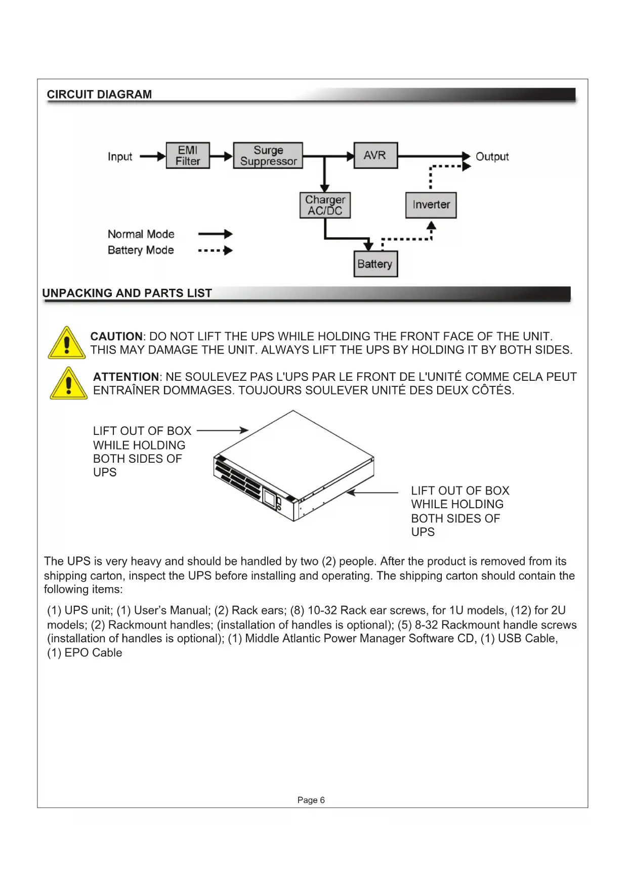
Circuit Diagram 6
Unpacking and Parts List 6
Installation and Mounting 7
Front Panel Descriptions 8 - 9
UPS-S500R/S1000R Rear Panel Descriptions 10
UPS-S1500R/S2200R Rear Panel Descriptions 11
Battery Charging 12
EPO (Emergency Power Off) Port Connection 12
Estimated Runtimes 12
Battery Replacement Warnings 13
UPS-S500R/S1000R Series Battery Replacement 14
UPS-S1500R/S2200R Series Battery Replacement 15
Troubleshooting 16
Technical Specifications UPS-S500R/UPS-S1000R Series 17
Technical Specifications UPS-S1500R/UPS-S2200R Series 18
Technical Specifications (All Models) 19
Warranty 20
Warranty Registration 20

IMPORTANT SAFETY INSTRUCTIONS SAVE THESE INSTRUCTIONS

Please read and follow all instructions carefully during installation and operation of this unit. Read this manual thoroughly before attempting to unpack, install or operate.

The lightning flash with the arrowhead symbol, within an equilateral triangle is intended to alert the user to the presence of uninsulated dangerous voltage within the product's enclosure that may be of sufficient magnitude to constitute a risk of electric shock to persons.

The exclamation point within an equilateral triangle is intended to alert the user to the presence of important operating and maintenance (servicing) instructions in the literature accompanying the appliance.

CAUTION: The UPS must be connected to a grounded AC power outlet with fuse or circuit breaker protection.

CAUTION: The battery can energize hazardous live parts inside the unit, even when the AC input power is disconnected.

CAUTION: To prevent the risk of fire or electric shock, install in a temperature and humidity controlled indoor area, free of conductive contaminants. (Please see specifications for acceptable temperature and humidity range).

CAUTION: To avoid electric shock, turn off the unit and unplug it from the AC power before servicing the battery.

CAUTION: To reduce the risk of electric shock, do not remove the cover, except to service the battery. There are no serviceable parts inside, except for the battery.

CAUTION: Do not use for medical or life support equipment. Do not use in any circumstance that would affect operation or safety of any life support equipment, with any medical applications, or patient care.

CAUTION: Do not open or mutilate the batteries. Released material is harmful to the skin and eyes and may be toxic.

CAUTION: Do not dispose of batteries in a fire. The batteries may explode.

CAUTION: To reduce the risk of fire, connect only to a circuit provided with 20 amperes maximum branch overcurrent protection in accordance with the National Electrical Code, ANSI/NFPA 70.

CAUTION: To avoid electrical shock, turn off the unit and unplug it from the AC power before installing a component.

CAUTION: Do not plug the machine into an outlet that is not grounded. If you need to de-energize this equipment, turn off and unplug the unit.

CAUTION: Before replacing batteries, remove conductive jewelry such as chains, wrist watches and rings. High energy through conductive materials could cause severe burns.

CAUTION: (Only required for unit with HB flame class battery) Not for use in a computer room as defined in the Standard for the Protection of Electronic Computer/Data Processing Equipment, ANSI/NFPA 75.

CAUTION: Ensure the wall outlet and UPS are located near the equipment being attached for proper accessibility.

CONSIGNES DE SÉCURITÉ IMPORTANTES CONSERVER CES INSTRUCTIONS

NOTE: This equipment has been tested and found to comply with the limits for a Class B digital device, pursuant to Part 15 of the FCC Rules. These limits are designed to provide reasonable protection against harmful interference in a residential installation. This equipment generates, uses and can radiate radio frequency energy and, if not installed and used in accordance with the instructions, may cause harmful interference to radio communications. However, there is no guarantee that interference will not occur in a particular installation. If this equipment does cause harmful interference to radio or television reception, which can be determined by turning the equipment off and on, the user is encouraged to try to correct the interference by one or more of the following measures:
- Reorient or relocate the receiving antenna.
- Increase the separation between the equipment and receiver.
- Connect the equipment into an outlet on a circuit different from that to which the receiver is connected.
- Consult the dealer or an experienced radio/TV technician for help.
WARNING: A shielded-type power cord is required in order to meet FCC emission limits and also to prevent interference to the nearby radio and television reception. It is essential that only the supplied power cord be used. Use only shielded cables to connect I/O devices to this equipment.
WARNING: Any changes or modifications not expressly approved by the guarantee of this device could void the user's authority to operate the equipment.
UNPACKING AND PARTS LIST

CAUTION: DO NOT LIFT THE UPS WHILE HOLDING THE FRONT FACE OF THE UNIT. THIS MAY DAMAGE THE UNIT. ALWAYS LIFT THE UPS BY HOLDING IT BY BOTH SIDES.

ATTENTION: NE SOULEVEZ PAS L'UPS PAR LE FRONT DE L'UNITÉ COMME CELA PEUT ENTRAÎNER DOMMAGES. TOUJOURS SOULEVER UNITÉ DES DEUX CÔTÉS.
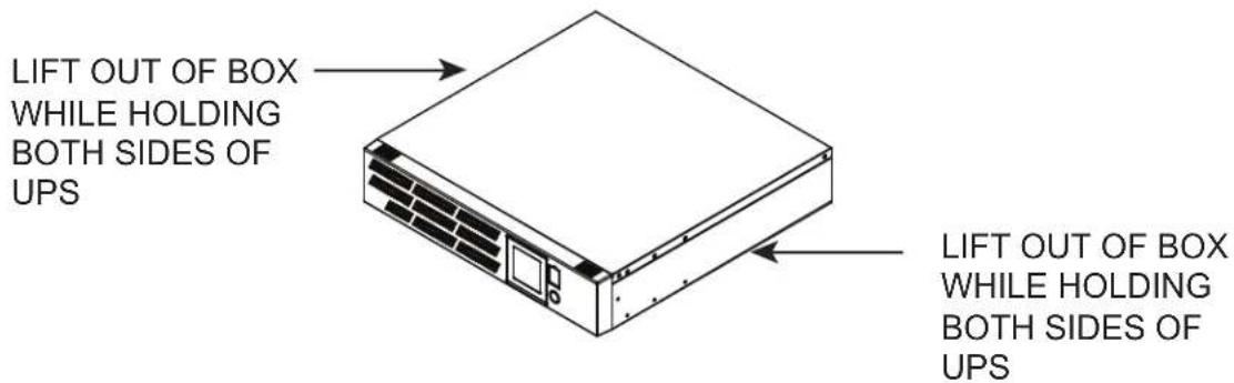
The UPS is very heavy and should be handled by two (2) people. After the product is removed from its shipping carton, inspect the UPS before installing and operating. The shipping carton should contain the following items:
(1) UPS unit; (1) User's Manual; (2) Rack ears; (8) 10-32 Rack ear screws, for 1U models, (12) for 2U models; (2) Rackmount handles; (installation of handles is optional); (5) 8-32 Rackmount handle screws (installation of handles is optional); (1) Middle Atlantic Power Manager Software CD, (1) USB Cable, (1) EPO Cable
INSTALLATION AND MOUNTING

CAUTION: THIS UNIT IS HEAVY,,LIFT CAREFULLY


ATTENTION: CET APPAREIL EST LOURD, SOULEVEZ AVEC ATTENTION

NOTE: Installation of handles is optional.
1) If using the provided handles install them now using provided 8-32 screws. (FIGURE A)
NOTE: The handles cannot be installed after the unit is rack-mounted.
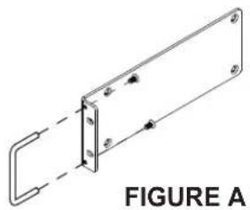
natural_image
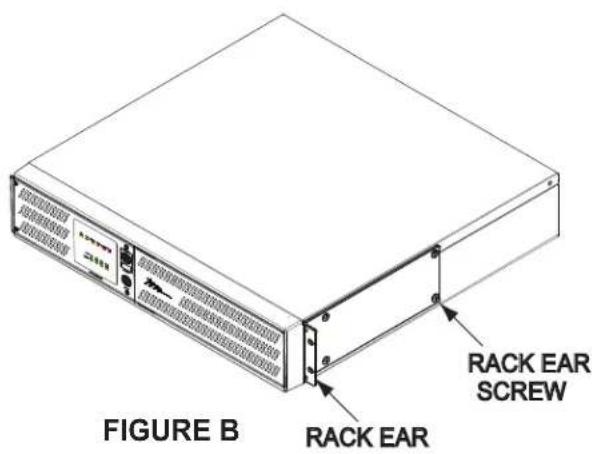
Technical line drawing of a rectangular frame with mounting holes and a curved side, labeled 'FIGURE A' (no text or symbols on the diagram itself)2) Install ears as shown using provided 10-32 screws. (FIGURE B)
3) Determine mounting location.
4) Carefully lift the unit to the mounting position constantly supporting the bottom.
5) Install the front of the unit to the rackrail. (FIGURE C)
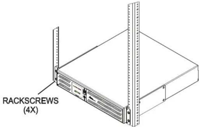
FIGURE C
FRONT PANEL DESCRIPTIONS
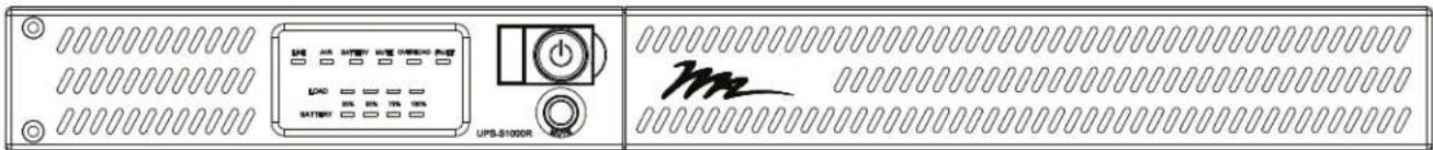
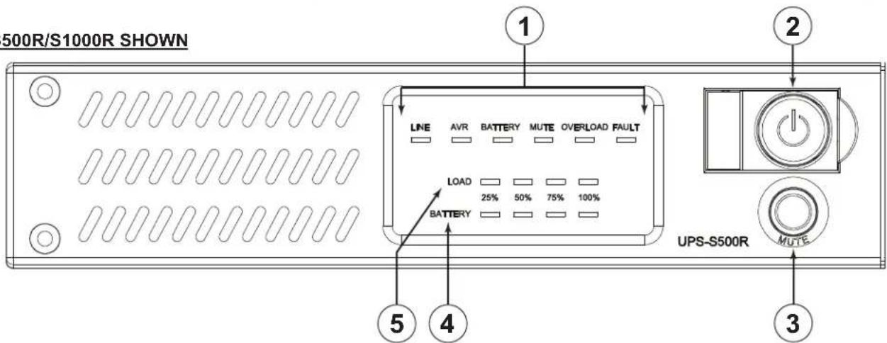
UPS-S500R/S1000R SHOWN
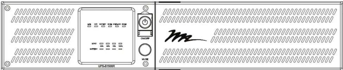
UPS-S1500R/S2200R SHOWN
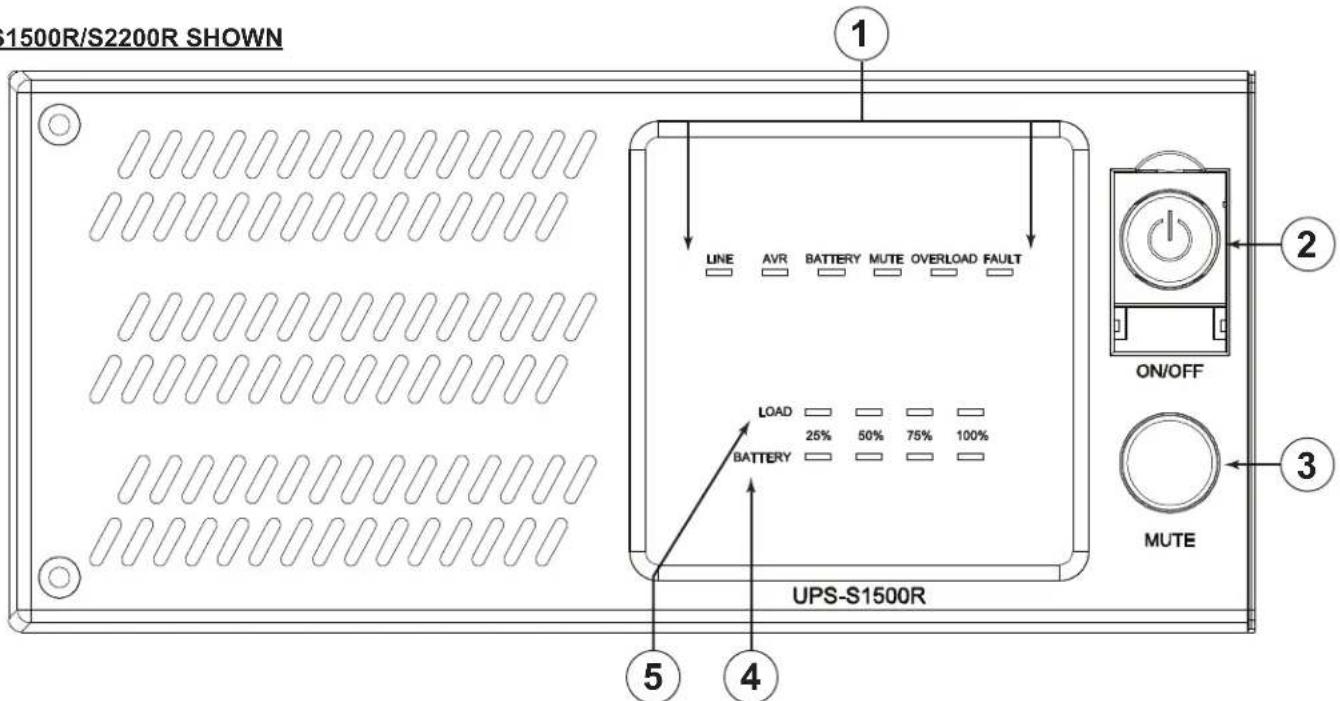
① LED STATUS DISPLAY:
a. LINE - Illuminates green when power is supplied by the AC mains. The LED will be off when the unit is battery back up mode.
b. AVR - Illuminates green to indicate that the UPS is boosting the line voltage.
c. BATTERY - Illuminates orange to indicate that the UPS is in battery backup mode. The LED is off when in line-interactive mode.
d. MUTE - Illuminates orange to indicate that the audible alarm is muted.
e. OVERLOAD - Illuminates red when in an overloaded (over-current) condition.
f. FAULT - Illuminates red to indicate an internal fault with the UPS. Contact MAP Technical Support. (1-800-266-7225 x1593)
FRONT PANEL DESCRIPTIONS (CONTINUED)
② POWER ON/OFF PUSH BUTTON : Press to turn on or off.
③ MUTE PUSH BUTTON: Press and hold for 2 seconds to mute the audible alarm. The 'Mute' LED will illuminate. Press and hold again to enable the audible alarm.
④ BATTERY BAR GRAPH: Indicates the approximate amount of battery capacity remaining in 25% increments. A fully charged battery will have all four LEDs illuminated green.
⑤ LOAD BAR GRAPH: Indicates the approximate percentage of load current drawn in 25% increments. A fully loaded UPS will have all four LEDs illuminated green.
UPS-S500R/S1000R REAR PANEL DESCRIPTIONS
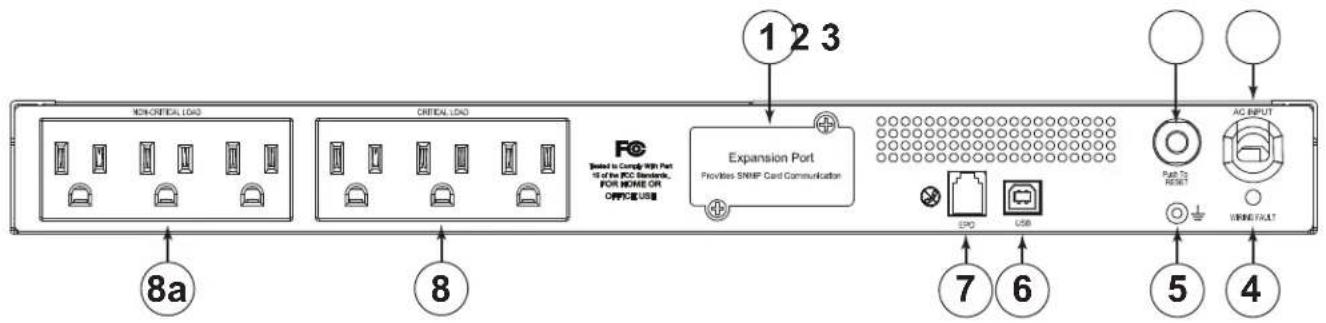
① EXPANSION PORT: Slot for optional Network Interface Card (NIC). Part Number UPS-IPCARD. Refer to the instructions with the UPS-IPCARD for configuration.
② AC OUTPUT CIRCUIT BREAKERS: Resettable circuit breakers provides AC output overload protection.
③ INPUT POWER CORD: Heavy-duty permanently attached power cord, connects UPS to mains power.
④ WIRING FAULT LED: Red LED that will illuminate if there is mis-wired input voltage such as an open ground, or reversed polarity.
⑤ GROUND/BONDING STUD
⑥ USB PORT: Connects the UPS directly to your computer for configuration.
⑦ EPO (EMERGENCY POWER OFF) PORT: The EPO port may be used to connect the UPS to a contact closure switch or control system to enable emergency shutdown (see page 12).
⑧ AC OUTLETS (BANK CONTROLLED): All AC outlets provide connected equipment with AC line power, surge protection and line noise filtering during normal operation. Automatic voltage regulation boosts low voltage without using battery power. All outlets provide battery power during blackouts and severe brownout or severe high voltage conditions. The non-critical load outlets (8a) can be configured to automatically shut down during a power outage event providing longer up-time for equipment plugged into the critical load outlets.
UPS-S1500R/S2200R REAR PANEL DESCRIPTIONS
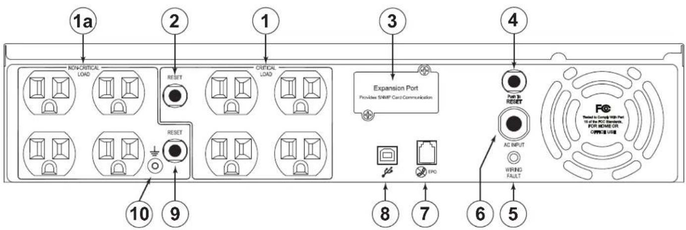
① AC OUTLETS (BANK CONTROLLED): All AC outlets provide connected equipment with AC line power, surge protection and line noise filtering during normal operation. Automatic voltage regulation boosts low voltage without using battery power. All outlets provide battery power during blackouts and severe brownout or severe high voltage conditions. The non-critical load outlets (1a) can be configured to automatically shut down during a power outage event providing longer up-time for equipment plugged into the critical load outlets.
② AC OUTPUT CIRCUIT BREAKERS (CRITICAL LOAD BANK): Resettable circuit breakers provides AC output overload protection.
③ EXPANSION PORT: Slot for optional Network Interface Card (NIC). Part Number UPS-IPCARD. Refer to the instructions with the UPS-IPCARD for configuration.
④ AC OUTPUT CIRCUIT BREAKERS (ALL OUTLETS): Resettable circuit breakers provides AC output overload protection.
⑤ WIRING FAULT LED: Red LED that will illuminate if there is mis-wired input voltage such as an open ground, or reversed polarity.
⑥ INPUT POWER CORD: Heavy-duty permanently attached power cord, connects UPS to mains power.
⑦ EPO (EMERGENCY POWER OFF) PORT: The EPO port may be used to connect the UPS to a contact closure switch or control system to enable emergency shutdown (see page 12).
⑧ USB PORT: Connects the UPS directly to your computer for configuration.
⑨ AC OUTPUT CIRCUIT BREAKERS (NON-CRITICAL LOAD BANK): Resettable circuit breakers provides AC output overload protection.
⑩GROUNDING/BONDING STUD
BATTERY CHARGING
The UPS is shipped from the factory with its internal battery fully charged. However, the battery may lose some charge during shipping and storage. Recharging the battery for at least eight hours is recommended to ensure that the battery's maximum charge capacity is achieved.
The UPS is equipped with an auto-charge feature. When the UPS is plugged into mains AC supply voltage, the battery will automatically recharge (the battery will charge with the UPS either turned on or off). To maintain optimal battery charge, leave the UPS plugged into an AC outlet at all times.
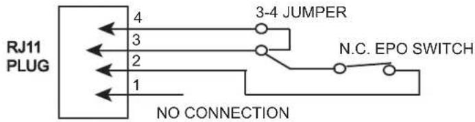
EPO (EMERGENCY POWER OFF) PORT CONNECTION
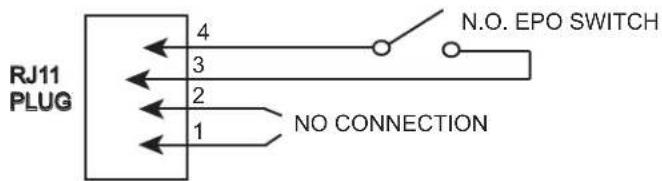
This feature is for those applications that require connection to an Emergency Power Off (EPO) circuit in case of fire or other emergency situation. When the UPS is connected to this circuit, it enables emergency shutdown of the UPS's inverter. Using the supplied gray cable, connect the EPO port of your UPS to a user-supplied normally closed or normally open switch according to the circuit diagram shown below. Press the Power switch to turn on the UPS after making the connections.
OPTION 1: USER SUPPLIED NORMALLY CLOSED SWITCH
OPTION 2: USER SUPPLIED NORMALLY OPEN SWITCH
ESTIMATED RUNTIMES
| MODEL | UPS-S500R Series | UPS-S1000R Series |
| ESTIMATED RUNTIME (Full Load) | 3 MINUTES | 3 MINUTES |
| ESTIMATED RUNTIME (Half Load) | 12 MINUTES | 13 MINUTES |
| MODEL | UPS-S1500R Series | UPS-S2200R Series |
| ESTIMATED RUNTIME (Full Load) | 6 MINUTES | 4 MINUTES |
| ESTIMATED RUNTIME (Half Load) | 18 MINUTES | 13 MINUTES |
BATTERY REPLACEMENT WARNINGS

CAUTION: RISK OF EXPLOSION IF BATTERY IS REPLACED BY AN INCORRECT TYPE.

CAUTION: Risk of Energy Hazard, 24 V, maximum 18 Ampere-hour batteries. Before replacing batteries, remove conductive jewelry such as chains, wrist watches, and rings. High energy through conductive materials could cause severe burns (UPS-S1500R/UPS-S2200R).

CAUTION: Risk of Energy Hazard, 24 V, maximum 16 Ampere-hour batteries. Before replacing batteries, remove conductive jewelry such as chains, wrist watches, and rings. High energy through conductive materials could cause severe burns (UPS-S500R/UPS-S1000R).
AVERTISSEMENTS DE REMPLACEMENT DE BATTERIE

ATTENTION: RISQUE D'EXPLOSION SI LA BATTERIE DE REMPLACEMENT PAR UN TYPE INCORRECT.

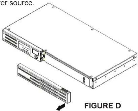
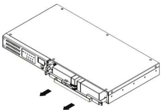
1) Power off the unit and disconnect it from its AC power source.
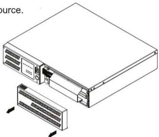
2) Gently remove the front panel. (FIGURE D)
natural_image
Technical line drawing of a server rack with internal components and directional arrows indicating movement (no text or symbols)FIGURE E
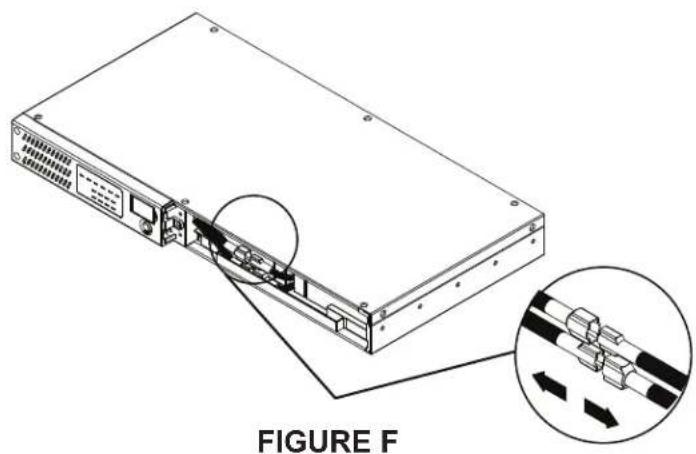
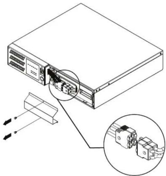
4) Disconnect the wires from the UPS to the battery. (FIGURE F)
natural_image
Line drawing of a server rack with internal components and ventilation slots (no text or symbols)FIGURE G
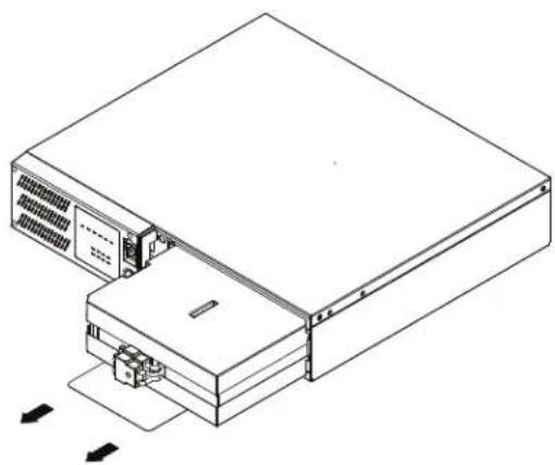
6) Remove the battery. Replace by performing the previous steps in reverse. (FIGURE H)
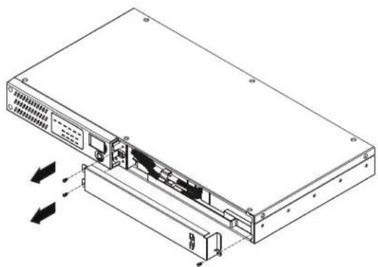
3) Remove the battery access panel. Three screws for the UPS-S500R, two for the UPS-S1000R. (FIGURE E)
natural_image
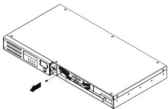
Diagram of a server rack with an inset showing internal cable connections (no text or symbols)5) Remove the one screw that secures the battery to the UPS. (FIGURE G)
natural_image
Isometric line drawing of a server rack with ventilation slots and ports, showing internal components and directional arrows (no text or symbols)FIGURE H
UPS-S1500R/S2200R SERIES BATTERY REPLACEMENT
1) Power off the unit and disconnect it from its AC power source.
2) Gently remove the front panel. (FIGURE I)
natural_image
Diagram of a server rack with internal components and connectors, showing connection to a device (no text or symbols present)FIGURE J
natural_image
Technical line drawing of a server rack with ventilation slots and cooling unit (no text or symbols)FIGURE I
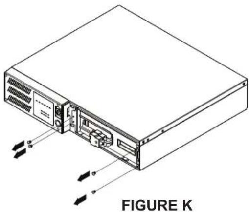
3) Remove the two screws affixing the battery access panel. Disconnect the wires from the UPS to the battery. (FIGURE J)
4) Remove the four screws that secures the battery to the UPS. (FIGURE K)
natural_image
Line drawing of a computer drive chassis with cooling unit and ventilation panel (no text or symbols)FIGURE L
natural_image
Isometric line drawing of a server rack with ventilation slots and external connectors (no text or symbols)5) Remove the battery. Replace by performing the previous steps in reverse. (FIGURE L)
TROUBLESHOOTING
| Problem | Possible Cause | Solution |
| Outlets do not provide power to equipment. | 1. Circuit breaker has tripped due to an overload.2. Batteries are discharged3. Unit has been damaged by a surge or spike.4. Non critical outlets have turned off automatically due to an overload. | 1. Turn the UPS off and unplug at least one piece of equipment. Wait 10 seconds, reset the circuit breaker, and then turn on the UPS.2. Recharge the unit for at least 8 hours.3. Contact Middle Atlantic Products at 1-800-266-7225.4. Push the bottom Reset button to turn on the Non critical outlets. |
| The UPS does not perform the expected runtime. | 1. Battery is not fully charged.2. Battery is degraded. | 1. Recharge the battery by leaving the UPS plugged in.2. Contact Middle Atlantic Products about replacement batteries at 1-800-266-7225. |
| The UPS will not turn on. | 1. The on/off switch is designed to prevent damage by rapidly turning it on and off.2. The UPS is not connected to an AC outlet.3. The battery is degraded.4. Mechanical problem. | 1. Turn the UPS off. Wait 10 seconds and then turn the UPS on.2. The UPS must be connected to a 110/120V outlet.3. Contact Middle Atlantic Products about replacement batteries at 1-800-266-7225.4. Contact Middle Atlantic Products at 1-800-266-7225. |
| Middle Atlantic Power Manager software is inactive | 1. The cable is connected to the wrong port.2. The unit is not providing battery power. | 1. Connect the cable to the UPS. You must use the cable that came with the UPS.2. Shutdown your computer and turn the UPS off. Wait 10 seconds and turn the UPS back on. This should reset the unit. |
TECHNICAL SPECIFICATIONS UPS-S500R/UPS-S1000R SERIES
| MODEL | UPS-S500R Series | UPS-S1000R Series |
| Capacity (VA) | 500 | 1000 |
| Capacity (Watts) | 300 | 600 |
| INPUT | ||
| Cord Length & Plug Type | 10ft. & NEMA 5-15P | |
| Input Voltage Range | 90 VAC - 140 VAC | |
| Input Frequency Range | 60 Hz +/- 3 Hz (auto sensing) | |
| OUTPUT | ||
| On Battery Output Voltage | Simulated Sine Wave at 120 VAC +/- 10% | |
| On Battery Output Frequency | 60 Hz +/- 1% | |
| Transfer Time (Typical) | 8 ms | |
| Overload Protection | On Utility: Circuit Breaker, On Battery: Internal Current Limiting | |
| SURGE PROTECTION AND FILTERING | ||
| Lighting/Surge Protection | Single Mode, L - N | |
| PHYSICAL | ||
| Output Receptacles | (6) NEMA 5-15R | (6) NEMA 5-15R |
| Dimensions: in. (cm) | 1U, 17.05 x 1.75 x 9.05(43.3 x 4.4 x 23) | 1U, 17.05 x 1.75 x 15.35(43.3 x 4.4 x 39) |
| Weight: Lb. (Kg) | 18 (8.2) 32 (15) | |
| BATTERY | ||
| Sealed Maintenance Free Lead Acid Battery | UPS-S500R: 6V/7.0AH x 2UPS-S1000R: 6V/7.0AH x 4 | |
TECHNICAL SPECIFICATIONS UPS-S1500R/UPS-S2200R SERIES
| MODEL | UPS-S1500R Series | UPS-S2200R Series |
| Capacity (VA) | 1500 | 2000 |
| Capacity (Watts) | 900 | 1320 |
| INPUT | ||
| Cord Length & Plug Type | 10ft. & NEMA 5-15P | 10ft. & NEMA 5-20P |
| Input Voltage Range | 90 VAC - 140 VAC | |
| Input Frequency Range | 60 Hz +/- 3 Hz (auto sensing) | |
| OUTPUT | ||
| On Battery Output Voltage | Simulated Sine Wave at 120 VAC +/- 10% | |
| On Battery Output Frequency | 60 Hz +/- 1% | |
| Transfer Time (Typical) | 8 ms | |
| Overload Protection | On Utility: Circuit Breaker, On Battery: Internal Current Limiting | |
| SURGE PROTECTION AND FILTERING | ||
| Lighting/Surge Protection | Single Mode, L - N | |
| PHYSICAL | ||
| Output Receptacles | (8) NEMA 5-15R | (8) NEMA 5-20R |
| Dimensions: in. (cm) | 2U, 17.05" x 3.5" x 15.25" (43.3 x 8.8 x 38.7) | |
| Weight: Lb. (Kg) | 48 (21.9) 52.7 (23.9) | |
| BATTERY | ||
| Sealed Maintenance Free Lead Acid Battery | UPS-S1500R: 12V/7.0AH x 4UPS-S2200R: 12V/9.0AH x 4 | |
TECHNICAL SPECIFICATIONS (ALL MODELS)
| All Models MODELS | |
| Warning Diagnostics | |
| Indicators | Power On, Wiring Fault, LED Display (Using Battery, AVR, Load Level, Battery Level) |
| Audible Alarms | On Battery, Low Battery, Overload |
| Environmental | |
| Operating Temperature | 32°F to 104°F (0°C to 40°C) |
| Operating Relative Humidity | 0 to 95% Non-Condensing |
| Communication | |
| Power ManagerTM Software | Windows 98/ME/NT/2000/XP/Vista/7 |
| Management | |
| Auto-Charger/Auto-Restart | Yes |
| Built-in USB Interface | Yes |
NOTE:
- A simulated sine wave may cause certain loads to behave inconsistently.
- Middle Atlantic does not recommend that equipment with active power factor correction be used with Standard UPS products due to incompatibility issues. Please refer to the user manual or specification sheet of the equipment being used verify power supply characteristics.
WARRANTY
WARRANTY
Middle Atlantic Products, Inc. (the "Company") warrants the UPS Series Uninterruptible Power Supply product to be free from defects in material or workmanship under normal use and conditions for a period of (3) three years from date of shipment by the Company, with the following exception: the internal battery is covered for (2) two years.
The Company's entire liability to the purchaser, and the purchaser's (or any other party's) sole and exclusive remedy, under this warranty shall be limited, at the Company's option, to either (a) return of and refund of the price paid for, or (b) repair or replacement at the Company's factory of the products purchased, or any part or parts thereof, which the Company has determined to be defective after inspection thereof at the Company's factory. This warranty does not cover damage due to acts of God, accident, misuse, abuse or negligence by parties other than the Company, or any modification or alteration of the products. In addition, this warranty does not cover damage due to improper handling, assembly, installation or maintenance.
THIS WARRANTY IS IN LIEU OF ALL OTHER WARRANTIES OF ANY KIND, EITHER EXPRESSED OR IMPLIED, INCLUDING, BUT NOT LIMITED TO, IMPLIED WARRANTIES OF MERCHANTABILITY AND FITNESS FOR A PARTICULAR PURPOSE.
TO THE MAXIMUM EXTENT PERMITTED BY APPLICABLE LAW, IN NO EVENT SHALL THE COMPANY BE LIABLE FOR ANY SPECIAL, INCIDENTAL, INDIRECT, OR CONSEQUENTIAL DAMAGES WHATSOEVER (INCLUDING, WITHOUT LIMITATION, DAMAGES FOR LOSS OF BUSINESS PROFITS, BUSINESS INTERRUPTION OR ANY OTHER PECUNIARY LOSS) ARISING OUT OF THE USE OF THE PRODUCTS PURCHASED, EVEN IF THE COMPANY HAS BEEN ADVISED OF THE POSSIBILITY OF SUCH DAMAGES. THE COMPANY'S LIABILITY TO THE PURCHASER (OR ANY OTHER PARTY) HEREUNDER, IF ANY, SHALL IN NO EVENT EXCEED THE PURCHASE PRICE OF THE PRODUCTS PAID TO THE COMPANY.
Middle Atlantic Products
Voice 973-839-1011 - Fax 973-839-1976 / International Voice +1 973-839-8821 - Fax +1 973-839-4982 middleatlantic.com - info@middleatlantic.com
Middle Atlantic Canada
Voice 613-836-2501 - Fax 613-836-2690 / middleatlantic.ca - contactcanada@middleatlantic.com
Factory Distribution
USA: NJ - CA - IL Canada: ON - BC
At Middle Atlantic Products we are always listening. Your comments are welcome.
WARRANTY REGISTRATION
IMPORTANT NOTE
Please register your purchase.
http://www2.middleatlantic.com/ups/warranty/registration.aspx


Middle Atlantic Products
what great systems are built on™
middleatlantic.com ■ 800.266.7225