C3-24-LD2U - Audio-visual furniture Middle Atlantic - Free user manual and instructions
Find the device manual for free C3-24-LD2U Middle Atlantic in PDF.

User questions about C3-24-LD2U Middle Atlantic
0 question about this device. Answer the ones you know or ask your own.
Ask a new question about this device
Download the instructions for your Audio-visual furniture in PDF format for free! Find your manual C3-24-LD2U - Middle Atlantic and take your electronic device back in hand. On this page are published all the documents necessary for the use of your device. C3-24-LD2U by Middle Atlantic.
USER MANUAL C3-24-LD2U Middle Atlantic
DISPLAY MOUNT OPTION (C3-XX-LDXU)

natural_image
3D rendering of a modern TV or audio workstation with black and white panels, mounted on a wooden cabinet (no text or symbols visible)NOTE: A 1-Bay C3 credenza with a display mount option (C3-XX-LDXU) configured for a single displays (display not included) shown.
THANK YOU
Thank you for purchasing a C3 Series Display Mount option. Please read these instructions thoroughly before installing or assembling this product.
MIDDLE ATLANTIC.
A brand of □ legrand
100-00034 Rev C
IMPORTANT SAFETY INSTRUCTIONS - EN
- Read these instructions.
- Heed all warnings.
- Clean only with dry cloth.
- Keep these instructions.
- Follow all instructions.
- Only use attachments/accessories specified by the manufacturer.

DANGER HAZARDOUS VOLTAGE: The lightning flash with the arrowhead symbol, within an equilateral triangle is intended to alert the user to the presence of uninsulated dangerous voltage within the product's enclosure that may be of sufficient magnitude to constitute a risk of electric shock to persons.

WARNING: A warning alerts you to a situation that could result in serious personal injury or death.

CAUTION: A caution alerts you to a situation that may result in minor personal injury or damage to the product and/or property.
NOTE: A note is used to highlight procedures pertaining to the installation, operation, or maintenance of the product.

WARNING: Failure to read, understand and follow the following information can result in serious personal injury, damage to the equipment or voiding of the warranty. It is the responsibility of the Installer/User to ensure that this product is loaded according to specifications.

WARNING: Middle Atlantic Products, electrical systems conform to and should be properly grounded in compliance with requirements of the current National Electrical Code or codes administered by local authorities. All electrical products may present a possible shock or fire hazard if improperly installed or used. Electrical products may bear the mark of a Nationally Recognized Testing Laboratory (NRTL) and should be installed in conformance with current local and/or the National Electrical Code.

WARNING: Exceeding the weight ratings listed can result in serious injury or damage to the equipment. It is the responsibility of the Installer/User to ensure the components installed do not surpass the weight ratings as an unstable condition can occur which may cause possible injury or damage.

CAUTION: If there is visible damage on the product, it must not be installed.

CAUTION: Safety measures must be practiced at all times during the assembly of this product. Use proper safety equipment and tools for the assembly procedure to prevent personal injury.

CAUTION: Note that during construction, there must be no possibility of personal injury, for example the squeezing of fingers or arms.

CAUTION: For loading, always put heavier items at the bottom of the bays, not near the top, in order to help prevent the possibility of the furnishing tipping over.

CAUTION: The appliance is not intended for use by young children or infirm persons without supervision.
Safety Instructions: Rack Mount
Elevated Operating Ambient: If installed in a closed or multi-unit rack assembly, the operating ambient temperature of the rack environment may be greater than room ambient. Therefore, consideration should be given to installing the equipment in an environment compatible with the maximum ambient temperature (Tma) specified by the manufacturer.
Reduced Air Flow: Installation of the equipment in a rack should be such that the amount of air flow required for safe operation of the equipment is not compromised.
Mechanical Loading: Mounting of the equipment in the rack should be such that a hazardous condition is not achieved due to uneven mechanical loading.
Circuit Overloading: Consideration should be given to the connection of the equipment to the supply circuit and the effect that overloading of the circuit might have on overcurrent protection and supply wiring. Appropriate consideration of equipment nameplate ratings should be used when addressing this concern.
Reliable Earthing: Reliable earthing of rack-mounting equipment should be maintained. Particular attention should be given to supply connections other than direct connections to the branch circuit (e.g. use of power strips).
Disconnect Device (Pluggable Equipment): The socket-outlet shall be installed near the equipment and shall be easily accessible.
INSTRUCTIONS IMPORTANTES SUR LA SÉCURITÉ - FR
- Lire ces instructions.
| Model Number Weight Rating | |
| C3 1-Bay 24" (610 mm) and 32" (813 mm) Height | 50 lbs. (23 kg) Per Bay, 10 lbs. (5 kg) On Top, 100 lbs. (45 kg) Maximum Total Rated Load |
| C3 2-Bay 24" (610 mm) and 32" (813 mm) Height | 50 lbs. (23 kg) Per Bay, 20 lbs. (9 kg) On Top, 200 lbs. (91 kg) Maximum Total Rated Load |
| C3 3-Bay 24" (610 mm) and 32" (813 mm) Height | 50 lbs. (23 kg) Per Bay, 30 lbs. (14 kg) On Top, 300 lbs. (136 kg) Maximum Total Rated Load |
| C3 4-Bay 24" (610 mm) and 32" (813 mm) Height | 50 lbs. (23 kg) Per Bay, 40 lbs. (18 kg) On Top, 400 lbs. (181 kg) Maximum Total Rated Load |
| Slide-Out Rack Option (C3-TECHKIT4-SO) | 50 lbs. (23 kg) Maximum Total Rated Load |
| Fixed Rack Option (C3-TECHKIT4-ST) | 50 lbs. (23 kg) Maximum Total Rated Load |
| Shelf Kit Option (C3-SHELFKIT, Weight Per Shelf) | 30 lbs. (14 kg) Maximum Total Rated Load |
| Display Mount Option (C3-XX-LDXU, Weight Per Screen) | 150 lbs. (68 kg) Maximum Total Rated Load |

WARNING: This product is intended for use only with the products and maximum weights indicated. Use with other products or products heavier than the maximum weights indicated may result in instability causing possible injury. Total equipment weight must not exceed the amounts indicated on the previous table.

If any pieces are missing or damaged, please report it immediately to Technical Support at av.support@legrand.com or (866) 977-3901.

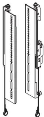
natural_image
Two identical vertical metal structures with embedded bolts and mounting brackets, no text or symbols present.Upright Pair A

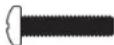
(4x)
14 "-20 x 38 " PMSCREW Hex Head Thread Forming Screw B

(4x) 14 " -20 x 2 12 " Bolt
E

(4x) 14 " Washer
F

SNAPTOGGLE® Anchor
C

(4x)
10-32
Flange Nut
D

Horizontal Extrusion G
| Single or Dual Display Width | |
| Single | 36" (914 mm) |
| Dual | 96" (2,438 mm) |

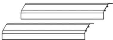
natural_image
Two identical cylindrical electronic components with 'CHIEF' branding, shown in 3D line art style (no additional text or symbols)Extrusion End Cap Pair H

(4x) 14 "-20 x 12 " Pan Head Phillips Thread Tapping End Cap Screws J
SUPPLIED COMPONENTS AND HARDWARE (CONTINUED)

(4x)
5/16" × 3½"
Square Single Wire
Snap Pin
K

(2x)
5/16"-18 x 1/2" Flush
Head Self-Clinching Stud
L
| Model Number | Qty. |
| C3-24-LD1U | 2 |
| C3-32-LD1U | 2 |
| C3-24-LD2U | 4 |
| C3-32-LD2U | 4 |

(2x)
5/16"-18 Flange Nut
M
| Model Number | Qty. |
| C3-24-LD1U | 2 |
| C3-32-LD1U | 2 |
| C3-24-LD2U | 4 |
| C3-32-LD2U | 4 |
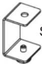
Interface
Standoff Bracket
[Non-Text]
| Model Number | Qty. (Number of Pairs) |
| C3-24-LD1U | 2 |
| C3-32-LD1U | 2 |
| C3-24-LD2U | 4 |
| C3-32-LD2U | 4 |
natural_image
Technical line drawing of two vertical mechanical components with mounting feet (no text or symbols)Interface Pair
P
| Single or Dual Display Qty. (Number of Pairs) | |
| Single (C3-24-LD1U and C3-32-LD1U) | 1 Pair |
| Dual (C3-24-LD2U and C3-32-LD2U) | 2 Pairs |
natural_image
Two identical 3D rectangular blocks with stepped edges, no text or symbols presentUpright Cover Pair
R
| Frame Height | Cover Height |
| 24" (610 mm) | 26.5" (673 mm) |
| 32" (813 mm) | 18.5" (470 mm) |
INTERFACE HARDWARE (9900-002248)
NOTE: Two sets of the following interface hardware (9900-002248) are provided for dual display installations.

(4x)
M4 x 12mm
Pan Head Screw
IH-A

(4x)
M6 x 12mm
Pan Head Screw
IH-G
(4x)
M4 x 20mm
Pan Head Screw
IH-B

(4x)
M6 x 20mm
Pan Head Screw
IH-H

(4x)
M4 x 25mm
Pan Head Screw
IH-C

(4x)
M6 x 25mm
Pan Head Screw
IH-J

(4x)
M5 x 12mm
Pan Head Screw
IH-D

(4x)
M8 x 12mm
Pan Head Screw
IH-K

(4x)
M5 x 20mm
Pan Head Screw
IH-E

(4x)
M5 x 25mm
Pan Head Screw
IH-F

(4x)
M8 x 20mm
Pan Head Screw
IH-L
(4x)
M8 x 30mm
Pan Head Screw
IH-M

(8x)
Spacer
IH-N

(4x)
Washer
IH-P
NOTE:
• To order more hardware, contact support at av.support@legrand.com or (866) 977-3901.
• Additional hardware is included that may not be required for your installation.
REQUIRED TOOLS
- Protective Eyewear
- Level
• #2 Phillips
Screwdriver
- Electric Drill
• 3/8" Socket -
2 Phillips Bit
- 1 / 2 " Wrench

WARNING: Use tools with caution and follow all necessary safety protocols.
- Only use this instruction sheet to install your C3 Series Display Mount option after you refer to the C3 Series Credenza Frame instruction sheet (100-00032) and secure your frame to the wall using the default (frame feet) installation height.
- Do not use the display mount option (C3-XX-LDXU) if your installation requires the credenza mounted at a specific height and you cannot use the default (frame feet) installation height.
- If your installation includes a purchased fan kit and/or a large cover option (for your display option), after installing this and the other options you may have purchased for your credenza, refer to the C3 Series WoodKit instruction sheet (100-00040) to install your woodkit, and then refer to the C3 Series Fan Kit (C3-FANKIT) instruction sheet (100-00039) and/or C3 Series Display Mount Large Cover Option instruction sheet (100-00035) to install your fan kit and/or your large cover option, respectively. Kits and options other than the fan kit and large cover option should be installed before your woodkit is attached to the frame
- Attaching display(s) (display(s) not included) to the horizontal extrusion must be done as the final part of your C3 installation process. For more information, see "Attaching Display(s) to the Horizontal Extrusion" on page 11.
- Instruction sheets may also be accessed at www.legradav.com.
SETTING MACRO DISPLAY HEIGHT ON YOUR UPRIGHT PAIR
NOTE:
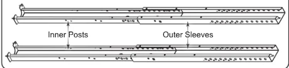
• Each upright includes the following pieces: pre-assembled lower portions comprised of inner posts and outer sleeves, and horizontal mounts at the tops as shown. (FIGURE A)
Upright Pair Pre-assembled Lower Portions Upright Pai
text_image
Inner Posts Outer SleevesHorizontal Mounts

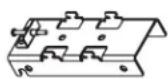
FIGURE A
SETTING MACRO DISPLAY HEIGHT ON YOUR UPRIGHT PAIR (CONTINUED)
- There are 4 macro display height intervals labeled A, B, C, and D, along the inner post of each upright. (FIGURE B)
-
Each macro display height interval is spaced 6" (152 mm) apart.
-
Start determining which macro display height interval (A, B, C, or D) you should use in order to properly accommodate your display(s) by carefully considering measurements described on the next page.

text_image
A Inner Posts B C D Outer Sleeves FIGURE B- Refer to the information provided with your display(s) to get an accurate display height measurement as shown. (FIGURE C)
- Take your accurate display height measurement along with your C3 height (either 32" (813 mm) or 24" (610 mm)) and make sure your selected macro display height interval provides adequate display clearance after reviewing the specific 6" (152 mm) upright pair height range on the table provided.
NOTE:
- A 4-Bay C3 credenza with a display mount option (C3-XX-LDXU) configured for dual displays (displays not included) shown.
- Although not installed yet in the overall procedure, the woodkit is shown on the frame for an accurate credenza height, display clearance, and provide a general idea of the look your display mount provides.
text_image
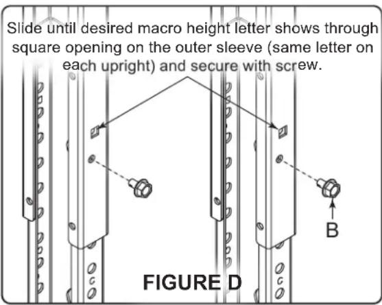
Slide until desired macro height letter shows through square opening on the outer sleeve (same letter on each upright) and secure with screw. FIGURE D| Macro Display Label | Height Range of Upright Pair |
| A | 51" (1295 mm) to 57" (1447 mm) |
| B | 57" (1447 mm) to 63" (1600 mm) |
| C | 63" (1600 mm) to 69" (1752 mm) |
| D | 69" (1752 mm) to 75" (1905 mm) |
NOTE: Large Cover option (C3-XX-XCVR-BK) does not fit from 51" (1295 mm) to 53" (1346 mm).

text_image
e Macro Display Height Measurement Display Height Display Clearance FIGURE C C3 Height- Slide the inner post through the outer sleeve on one of the uprights until your desired macro height letter shows through the square opening (the same letter for each upright) on the outer sleeve as shown. (FIGURE D)
- Use electric drill, 38 " socket, and a 14 "-20 x 38 " hex head thread forming screw (B) to secure each upright to your selected macro height letter.
ATTACHING UPRIGHT PAIR TO THE FRAME AND YOUR WALL
NOTE:
• Each upright is attached to specific frame locations based on single or dual display installation.
- All models support single display installation.
- Only 3- and 4-Bay models support dual display installation.
- Use the following figure to determine where to attach each upright to your frame for single or dual display installation. (FIGURE E)

text_image
15" (381 mm) 15" (381 mm) 15" (381 mm) 15" (381 mm) Upright Pair Installation for Single Display (All Models)FIGURE E

text_image
38" (965 mm) 38" (955 mm) Upright Pair Installation for Dual Displays (3- and 4-Bay Models Only)- Insert the studs on the bottom (inner post) on both of the macro height secured uprights into the holes on the top of the frame and place them against your wall.
- Use level to ensure the uprights are vertically aligned on your wall before proceeding to step 4 and marking the wall inside the top slots of the 4 upper keyholes on the uprights.
ATTACHING UPRIGHT PAIR TO THE FRAME AND YOUR WALL (CONTINUED)
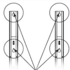
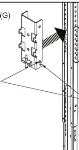
- Use a pencil and mark your wall inside the top slots of the 4 upper keyholes on the uprights (A) as shown. (FIGURE F)
- Remove the uprights from your frame and wall.
NOTE: Adjust torque on electric drill to the "drill" setting.
- Use electric drill and 12 " drill bit to drill holes in the marked locations on your wall.
natural_image
Pure electrical circuit lines without any symbolsMark inside the top slots of the 4 upper keyholes for drill locations.

- Insert SNAPTOGGLE® anchors (C) into holes by holding metal channels flat alongside plastic straps and sliding channels through holes.
NOTE:
- Refer to "Attaching Your Frame Using the Default (Frame Feet) Installation Height" on page 6 in the C3 Series Credenza Frame instruction sheet (100-00032) to revisit instructions on how properly use SNAPTOGGLE anchors in your type of wall.
- If you are not securing uprights using the provided SNAPTOGGLE anchors (preferred), and instead are going into wood studs or a solid concrete wall, you must provide your own lag bolt\ hardware.
text_image
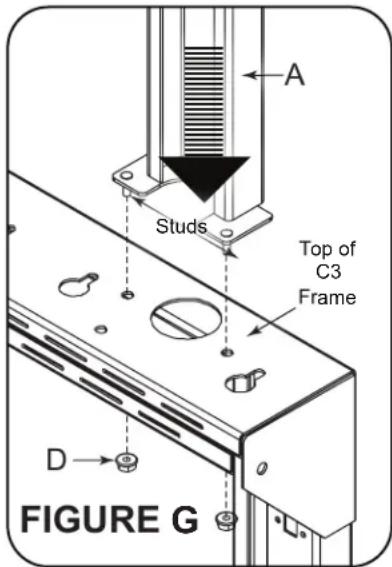
A Studs Top of C3 Frame D FIGURE G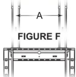
text_image
A FIGURE FNOTE: A 1-Bay C3 credenza with display mount option (C3-XX-LDXU) configured for a single display (displays not included) shown.
- Insert the studs on the bottom (inner post) on one of the macro height secured uprights into the holes on the top of the frame as shown. (FIGURE G)
NOTE: Verify the torque on your electric drill is on the lightest setting and only increase as necessary.
- Use electric drill 38 " socket and (2x) 10-32 flange nuts (D) to attach the upright to the frame.
- Repeat the previous steps to attach the other upright.
- Use electric drill, Phillips bit, 14 "-20 x 212 " bolts (E), and 14 " washers (F) to secure uprights to your wall. Do not overtighten.
NOTE:
- If you are not securing uprights using the provided SNAPTOGGLE anchors (preferred), and instead are going into wood studs or a solid concrete wall, you must provide your own lag bolt hardware.
- For more information, refer to “Attaching Your Frame Using the Default (Frame Feet) Installation Height” on page 6 in the C3 Series Credenza Frame instruction sheet (100-00032).

- Slide the interlock tabs on the upright pair horizontal mounts (positioned with the set screws on the bottom) into the two channels on the back of the horizontal extrusion (G) as shown. (FIGURE H)
NOTE: Verify the torque on your power driver is on the lightest setting and only increase as necessary. - Use electric drill, #2 Phillips bit, extrusion end caps (H) and (4x)14 "-20 x 12 " end cap screws (J) to attach an end cap on each side of the horizontal extrusion.
NOTE:
- There are 7 micro display height intervals labeled 1, 2, 3, 4, 5, 6, and 7 on the top of the pre-assembled lower portion of your upright pair.
- Each micro display height interval is spaced 1" (25 mm) apart.
- While carefully lifting the extrusion and placing the horizontal mounts over the upright pair, use the notch openings on the bottom of the mounts to select your micro display height interval (the same number for each horizontal mount) and secure each one with a single wire snap pin (K) through the holes right above. (FIGURE J)
NOTE: Horizontal extrusion (G) removed for clarity.
Secure micro display height setting with single wire snap pins (K) through horizontal bracket holes and uprights.
FIGURE J
text_image
(G)Micro display height intervals labeled 1 - 7 along the outer sleeve of each upright.
natural_image
Technical diagram showing a mechanical assembly with a bracket and a vertical rod, no text or symbols presentSlide horizontal brackets along sleeves until desired micro height number shows through notch openings (same number for both uprights).
- Center the horizontal extrusion with your credenza and then use a #2 Phillips screwdriver to tighten the screw on the bottom of each horizontal mount to fix it in place.
- Carefully attach the covers (R) to the front of your uprights.
FOR DUAL DISPLAY CONFIGURATIONS ONLY: If you purchased a C3 Series Display Mount Large Cover Option (C3-XX-XCVR-BK) for your dual display configuration, refer to the instruction sheet (100-00035) and use the option instead.
ATTACHING DISPLAY(S) TO THE HORIZONTAL EXTRUSION
NOTE: This topic must be done as the final part of your C3 installation process. Meaning, if you have not yet installed any other C3 Series options you may have purchased for your credenza, your woodkit, fan kit (if purchased), and large cover option (if purchased), you must first complete those steps (in that order) before returning to this topic and attaching your display(s) (display(s) not included) to the horizontal extrusion.
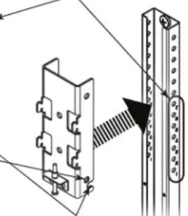
- Use 12 " wrench, 5/16"-18 x 12 " studs (L), and flange nuts (M) to attach interface standoff brackets (N)
text_image
P N M N P L FIGURE K- Select from the appropriate size and length pan head screws from the interface hardware (IH-A) through (IH-M) for use with your display.
NOTE:
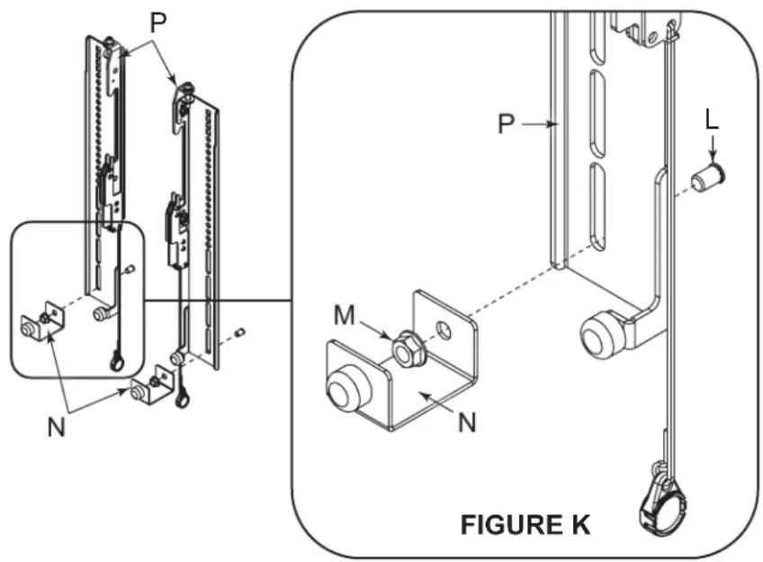
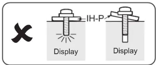
- Make sure the selected pan head screw length does not bottom out in the mounting hole on your display, or damage may occur. (FIGURE L)
- If you feel any resistance, stop immediately and try either a shorter screw or use spacers (IH-N) to take up slack.
- Verify the torque on your electric drill is on the lightest setting and only increase as necessary.
text_image
✓ IH-P Display IH-P IH-N DisplayFIGURE L
text_image
X Display IH-P DisplayATTACHING YOUR DISPLAY TO THE HORIZONTAL EXTRUSION (CONTINUED)
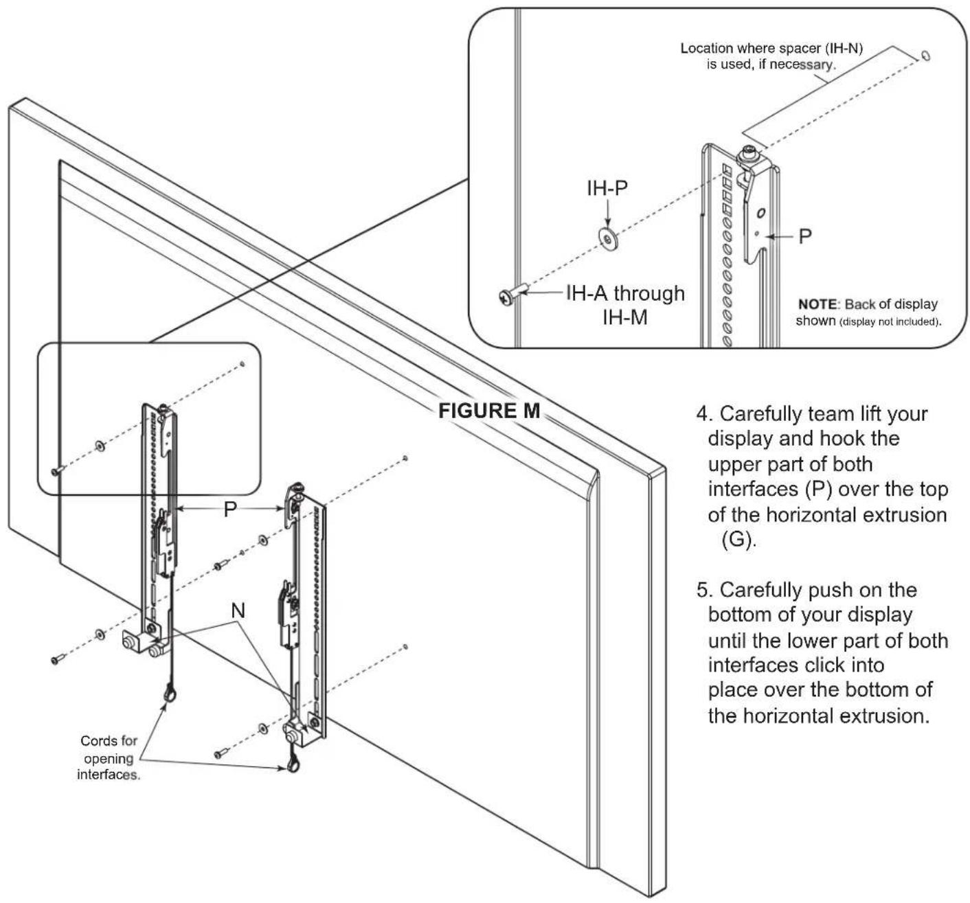
- Use electric drill, Phillips bit, (4x) interface pan head screws (IH-A) through (IH-M), spacers (IH-N), and washers (IH-P) to attach the interface pair to the back of your display as shown. (FIGURE M)
text_image
Location where spacer (IH-N) is used, if necessary. IH-P IH-A through IH-M NOTE: Back of display shown (display not included). FIGURE M 4. Carefully team lift your display and hook the upper part of both interfaces (P) over the top of the horizontal extrusion (G). 5. Carefully push on the bottom of your display until the lower part of both interfaces click into place over the bottom of the horizontal extrusion. Cords for opening interfaces.TIP: Use the magnets on each ring to stow the cords out of view behind your display.
NOTE: Remove your display by pulling down on the cords to open the interfaces, and then bringing the bottom forward from the horizontal extrusion while lifting up and away from the wall.
UNDERSTANDING NEXT STEPS
If your installation includes a purchased fan kit and/or a large cover option (for your purchased display option), after installing this and any other options you may have purchased for your credenza, refer to the C3 Series WoodKit instruction sheet (100-00040) to install your woodkit, and then refer to the C3 Series Fan Kit (C3-FANKIT) instruction sheet (100-00039) and/or C3 Series Display Mount Large Cover Option instruction sheet (100-00035) to install your fan kit and/or your large cover option, respectively.
NOTE:
- Kits and options other than the fan kit and large cover option should be installed before your woodkit is attached to the frame.
- Attaching your display(s) (display(s) not included) to the horizontal extrusion of the display mount option (C3-XX-LDXU, if purchased) must be done as the final part of your C3 installation process. For more information, refer to "Attaching Your Display to the Horizontal Extrusion" on page 11.
WARRANTY
For warranty information, refer to www.legrandav.com/policies/warranty_information.
Contacting Corporate Headquarters
P: (866) 977-3901 | F: (877) 894-6918 | www.legrandav.com | av.support@legrand.com
Contacting Middle Atlantic Canada
P: (888) 766-9770 | F: (888) 599-5009 | ca.middleatlantic.com | av.canada.customerservice@legrand.com
Contacting Middle Atlantic Europe, Middle East, and Africa (EMEA) Technical Support
P: +31 495-726-003 | av.emea.middleatlantic.support@legrand.com
United States (US)
Legrand | AV Headquarters 6436 City West Parkway Eden Prairie, MN, 55344, USA
European Union (EU)
Legrand AV Netherlands B.V. Franklinstraat 14 6003 DK, Weert, Netherlands
United Kingdom (UK)
Starline Holding Technology Ltd. (Authorized Representative) Unit C, Island Rd. Reading RG2, 0RP- UK
At Legrand AV Inc. we are always listening. Your comments are welcome.
Legrand AV is an ISO 9001 and ISO 14001 Registered Company.
MIDDLE ATLANTIC®
A brand of legrand®