
dB300a - Loudspeaker SAMSON - Free user manual and instructions
Find the device manual for free dB300a SAMSON in PDF.
| Product Type | Active two-way loudspeaker with built-in amplification |
| Brand | Samson |
| Model | dB300a |
| Dimensions (H x W x D) | 610 mm x 407 mm x 356 mm |
| Weight | 21.4 kg |
| Power Supply | 115 VAC / 230 VAC (selectable), 60/50 Hz |
| Amplifier Power | 250 W RMS (Class H) for woofer, 50 W RMS (Class AB) for tweeter |
| Low-Frequency Driver | 12-inch (31 cm) woofer with 3-inch voice coil, barium ferrite magnet |
| High-Frequency Driver | 1.75-inch compression tweeter with titanium diaphragm, 1-inch waveguide |
| Frequency Response | 60 Hz – 24 kHz (±3 dB) |
| Crossover Frequency | 2.3 kHz (18 dB/octave slope) |
| Inputs | MIC XLR balanced with phantom power, LINE combo XLR/6.35mm Jack balanced |
| Output | LINE OUTPUT XLR balanced |
| Equalization | Bass ±12 dB at 100 Hz, Treble ±12 dB at 10 kHz |
| High-Pass Filter | 80 Hz, 12 dB/octave slope (switchable) |
| Protection | Delay relay, AMP/CLIP indicator, overload protection |
| Mounting | 35 mm pole socket, 4 M6 suspension points |
| Floor Monitor Use | Tilt angles 30° or 45° depending on orientation |
| Construction | Durable PVC baffle, steel grille, reinforced corners |
| Optional Accessories | MB300U wall mount kit, MB300A suspension kit |
| Warranty | 3 years |
Frequently Asked Questions - dB300a SAMSON
User questions about dB300a SAMSON
0 question about this device. Answer the ones you know or ask your own.
Ask a new question about this device
Download the instructions for your Loudspeaker in PDF format for free! Find your manual dB300a - SAMSON and take your electronic device back in hand. On this page are published all the documents necessary for the use of your device. dB300a by SAMSON.
USER MANUAL dB300a SAMSON
natural_image
Line drawing of a Samsung air conditioner unit with top panel and base panel (no text or symbols)300 Watt 2-way Active Loudspeaker
Owners Manual
Safety Instructions/Consignes de sécurité/Sicherheitsvorkehrungen
WARNING
DO NOT EXPOSE THIS EQUIPMENT
TO RAIN OR MOISTURE
AVIS
RISQUE DE CHOC ELECTRONIQUE
NE PAS OUVRIR
CAUTION
FOR CONTINUED PROTECTION AGAINST RISK OF FIRE, REPLACE ONLY WITH SAME TYPE FUSE
ATTENTION
UTILISER UN FUSIBLE DE
RECHANGE DE MÊME TYPE
CAUTION
RISK OF ELECTRIC SHOCK
DO NOT OPEN

WARNING: To reduce the risk of fire or electric shock, do not expose this unit to rain or moisture. To reduce the hazard of electrical shock, do not remove cover or back. No user serviceable parts inside. Please refer all servicing to qualified personnel. The lightning flash with an arrowhead symbol within an equilateral triangle, is intended to alert the user to the presence of uninsulated "dangerous voltage" within the products enclosure that may be of sufficient magnitude to constitute a risk of electric shock to persons. The exclamation point within an equilateral triangle is intended to alert the user to the presence of important operating and maintenance (servicing) instructions in the literature accompanying the product.
Important Safety Instructions
- Please read all instructions before operating the unit.
- Keep these instructions for future reference.
- Please heed all safety warnings.
- Follow manufacturers instructions.
- Do not use this unit near water or moisture.
- Clean only with a damp cloth.
- Do not block any of the ventilation openings. Install in accordance with the manufacturers instructions.
- Do not install near any heat sources such as radiators, heat registers, stoves, or other apparatus (including amplifiers) that produce heat.
- Do not defeat the safety purpose of the polarized or grounding-type plug. A polarized plug has two blades with one wider than the other. A grounding type plug has two blades and a third grounding prong. The wide blade or third prong is provided for your safety. When the provided plug does not fit your outlet, consult an electrician for replacement of the obsolete outlet.
- Protect the power cord from being walked on and pinched particularly at plugs, convenience receptacles and at the point at which they exit from the unit.
- Unplug this unit during lightning storms or when unused for long periods of time.
- Refer all servicing to qualified personnel. Servicing is required when the unit has been damaged in any way, such as power supply cord or plug damage, or if liquid has been spilled or objects have fallen into the unit, the unit has been exposed to rain or moisture, does not operate normally, or has been dropped.
Copyright 2006, Samson Technologies Corp.
Printed October, 2006 - v1
Samson Technologies Corp.
45 Gilpin Avenue
Hauppauge, New York 11788-8816
Phone: 1-800-3-SAMSON (1-800-372-6766)
Fax: 631-784-2201
www.samsontech.com
^A K-TEAM
PRODUCTION
Table of Contents
ENGLISH
Introduction 2
dB300a Features 3
dB300a Layout.... 4
dB300a Front View Layout.... 4
dB300a REAR PANEL 5
Quick Set-Up. 6
Positioning the dB300a. 7
Operating the dB300a....8
Operating the dB300a....9
Setting Up Your dB300a System.... 10
Using Speaker Stands 10
Stacking the dB300a 10
Permanent Installation 11
Using the Fly-points....11
dB300a System Set-ups 12
Live Band PA System With Monitors....13
dB300a Wiring Guide....14
Optional Mounting Kits 61
Specifications....63
FRANÇAIS
Introduction 15
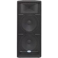
Congratulations on purchasing the Samson dB300a active loudspeaker! The dB300a speaker system by Samson takes the concept of powered PA systems to a new level. By combining 300 watts of super clean power, advanced active processing and the highest quality speaker and cabinet components, the dB300a provides studio quality sound for any kind of live sound reinforcement application. The loudspeaker features a super heavy-duty, custom designed, 12-inch low frequency driver and a 1.75 inch titanium diaphragm high frequency driver on a 1" throat, wide dispersion horn. The dB300a offers crystal-clear audio and an ultra-wide sound field. The top end is clear, sweet and articulate. The low-end is enormous. The dB300a is powered by a Class H amplifier that pumps 250 Watts to the low frequency driver and a Class AB amp that provides 50 Watts to the high frequency section—more than enough power to fill any large club. The efficient Class H amplifier design provides the power to deliver transient spikes with incredible punch and sonic purity. The dB300a goes beyond concert-quality to studio-quality thanks to Samson's exclusive Optimax processing. Optimax processing uses sophisticated circuitry to compress and limit output at ideal levels. This allows the dB300a to provide huge volume levels without sacrificing low end. The dB300a offers a practical back-panel, mixer-like preamp section that provides mic and line inputs with individual input level controls. Controls for the selectable low pass filter and extension output selection are also included. The trapezoidal shape of the speaker cabinet offers more than just superior acoustics, not only is it a front-firing PA speaker, the dB300a's are also designed to operate as wedge-style monitors. Adding to the dB300a's practical design is a catalog of mounting options. With the dB300a, setup and break down is quick and easy. The compact cabinet can be easily stacked, using the built-in stacking bumpers or stand mounted using the integral 1 3/8" pole mount receptacle. For permanent installations, the enclosures can be fixed to a wall or ceiling using the optional MB300U U-bracket mounting kit. The dB300a can also be suspended using the four built-in fly points and fixed in arrays using the MB300A array kit. If you are traveling to different venues with your loudspeaker system, the heavy-grade steel grill, scuff-resistant textured finish and rigid corners offer excellent protection against wear and tear on the road. As fixed sound reinforcement or as a durable, great-sounding road PA, the dB300a active monitor is ideal for sound professionals and performers looking for serious power and studio monitor sound quality from a PA speaker system.
In these pages, you'll find a detailed description of the features of the dB300a PA system, as well as a description of its front and rear panels, step-by-step instructions for its setup and use, and full specifications. You'll also find a warranty card enclosed—please don't forget to fill it out and mail it in so that you can receive online technical support and so we can send you updated information about these and other Samson products in the future. Also, be sure to check out our website (www.samsontech.com) for complete information about our full product line.
With proper care and adequate air circulation, your dB300a will operate trouble free for many years. We recommend you record your serial number in the space provided below for future reference.
Serial number:
Date of purchase: ____
Should your unit ever require servicing, a Return Authorization number (RA) must be obtained before shipping your unit to Samson. Without this number, the unit will not be accepted. Please call Samson at 1-800-3SAMSON (1-800-372-6766) for a Return Authorization number prior to shipping your unit. Please retain the original packing materials and if possible, return the unit in the original carton and packing materials. If you purchased your Samson product outside the United States, please contact your local distributor for warranty information and service.
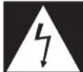
dB300a Features
natural_image
Technical line drawing of a speaker with antenna and cover (no text or symbols)The Samson dB300a active two-way loudspeaker is an all-in-one solution for live sound. Here are some of its main features:
- Two-way Active Loudspeaker
- Custom designed, heavy-duty, 12-inch low frequency driver with 3-inch voice coil.
- 1" throat, high-frequency compression driver with 1.75-inch titanium diaphragm.
- Efficient 250 watt, Class H power amplifier for low frequency transducer with High Speed, High Current MOSFET rail switches.
- 50 watt class AB amplifier for high frequency compression driver.
- Massive toroidal power transformer.
• Balanced line level input with level control.
• Balanced microphone input with level control and Phantom Power for condenser microphones. - Sophisticated, multi-band dynamics processor with audibly transparent limiting.
- Internal 24 dB/octave time aligned electronic crossover.
- Separate bass and treble controls.
- Defeatable low cut filter.
• 30 and 45-degree monitor angles for near and far field coverage. - Standard 1 3/8-inch (35mm) speaker stand receptacle.
- Four M6 fly-points for hanging installations.
- Optional U bracket and Array kits for wall mounting or hanging clusters.
- Rugged, road-worthy construction for high reliability.
- Multi-point amplifier protection for all fault conditions.
• Quality build and rugged construction ensure reliable performance from venue to venue.
• Three-year extended warranty.
dB300a Layout
dB300a Front View Layout
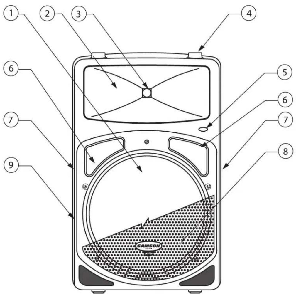
1 12 Inch Driver – Custom designed, heavy-duty, 12" low frequency driver with 3-inch voice coil provides deep bass.
2 Wide Dispersion Horn - 1 inch throat, 60 × 90 degree wide dispersion horn provides extensive coverage and linear off-axis response.
3 Titanium Compression Driver - 1.75 inch (44mm), titanium diaphragm with 1 inch opening.
4 Stacking Bumper – Gender mating bumpers for stacking dB300's.
5 Power LED – Blue Light Emitting Diode illuminates indicating the unit is powered on and ready for operation.
6 Bass Port—Two precision tuned, low frequency port tubes extend the bass response.
7 Handle – One of two ultra over sized rubber grip carry handles.
8 Steel Grill – Durable steel grill provides protection for, and easy access to LF driver.
9 Enclosure – Thick-wall, rugged PVC plastic enclosure.
dB300a Layout
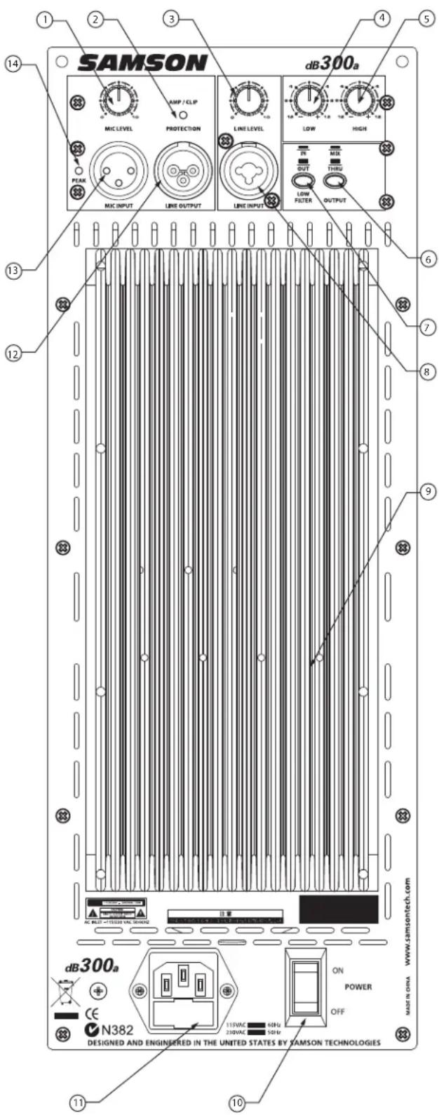
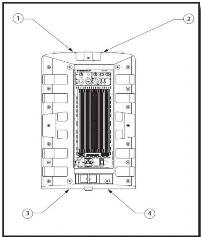
dB300a Rear Panel Layout
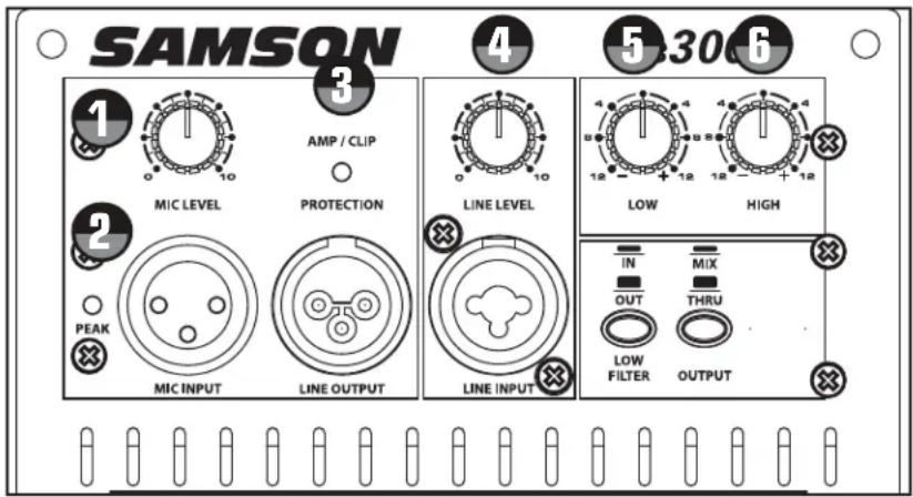
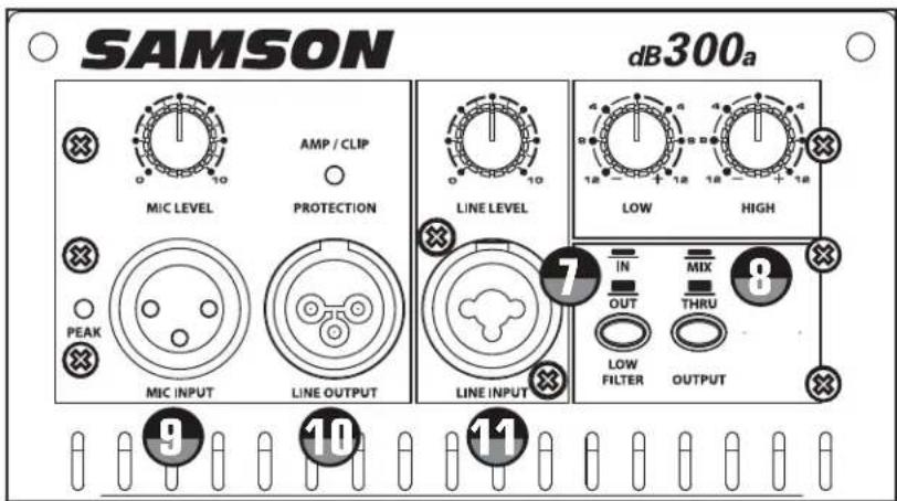
dB300a REAR PANEL
1 MIC LEVEL – Used to adjust the volume of the microphone input.
2 AMP / CLIP LED - Dual color LED lights Green when amp is active, flashes Red when the amp is clipped or stays Red indicating the amplifier is in protect mode.
3 LINE LEVEL – Used to control the level of the line input.
4 LOW FREQUENCY - Controls the low band of the Channel Equalizer, +/- 12 dB at 100Hz.
5 HIGH FREQUENCY - Controls the high band of the Channel Equalizer, +/- 12 dB at 10kHz.
6 OUTPUT SWITCH - This switch is used to select the signal that is sent to the Line Output. When the switch is in the up position, the signal on the Line Output is exactly the same as the signal on the Input. When the switch is in the down position the Line Output carries the MIX of the Mic and Line Inputs, as well as the High and Low Equalizer and Low Filter.
7 LOW FILTER SWITCH - When engaged, a Low-cut filter is employed at 80Hz with a roll-off slope of 12 dB per octave.
8 LINE INPUT CONNECTOR - Combo XLR plus 1/4 inch Input for connecting balanced or unbalanced line level signals.
9 HEAT SINK - Convection cooling of the internal power amplifier via massive aluminum extrusion.
10 POWER – Switches on the dB300a's main power.
11 AC POWER INLET – Connect the supplied standard IEC AC power cable here.
12 LINE OUTPUT - Male XLR connector used to link multiple dB300a's.
13 MIC INPUT CONNECTOR - XLR Input for connecting low impedance microphones to the Low-Noise pre-amp and Phantom Power.
14 PEAK LED- Red LED illuminates when the Mic input receives a clipped signal.
Quick Set-Up
In the following pages of this manual, you will find a detailed explanation of all the dB300a's functions and controls, but if you just want to get started quickly you can follow the steps below.
Using a Microphone
- Be sure that the dB300a's Power switch is set to the off position.
- Turn the LINE and MIC LEVEL controls fully counterclockwise to the off position.
- Connect the power cable to an AC socket.
- Using a standard XLR cable, plug a microphone into the dB300a's MIC INPUT.
- Switch the dB300a's Power switch to the ON position.
- While speaking into the microphone, slowly raise the MIC LEVEL control until you have reached the desired level.
Using a Line Level Signal
- Be sure that the dB300a's Power switch is set to the off position.
- Turn the LINE and MIC LEVEL controls fully counterclockwise to the off position.
- Connect the power cable to an AC socket.
- Using a standard XLR or 1/4 inch cable, connect a line level signal from a mixer or keyboard into the dB300a's LINE INPUT.
- Switch the dB300a's Power switch to the ON position.
- Now, run an audio signal from your mixer (like some music from a CD) while slowly raising the dB300a's LINE LEVEL control until you have reached the desired level.
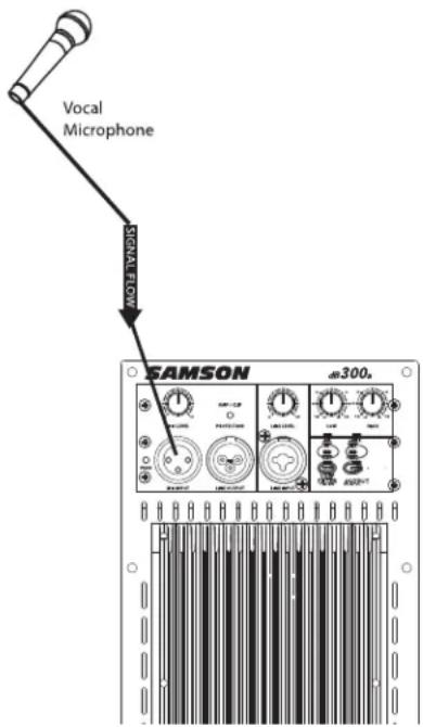
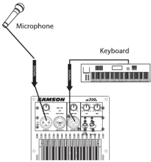
IMPORTANT NOTE: Be sure to keep the MIC LEVEL control all the way off if there is no microphone connected.
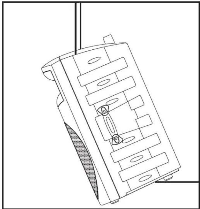
Positioning the dB300a
Microphone Positioning - How to Reduce Feedback
Feedback is the annoying howling and squealing that is heard when the microphone gets too close to the speaker and the volume is high. You get feedback when the microphone picks up the amplified signal from the speaker, and then amplifies through the speaker again, and then picks it up again, and so on and so on. In general, it is always recommended that any LIVE mic (a mic that's on) is positioned behind the speaker enclosures. This will give you the best level from your system before feedback. One possible exception is when you are adjusting the sounds of the microphones, since you want to listen in front of the speaker to hear properly. To do this, lower your mixers MAIN VOLUME while setting the EQ and effect from in front of the speakers. Once you have the sound you like, move the microphones to behind the speakers and raise the Main volume.
Speaker Placement
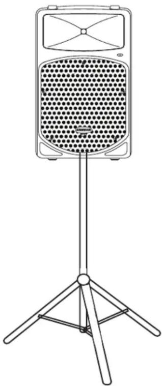
Whenever possible, it is a good idea to raise the speakers above the heads of the listening audience. The dB300a enclosures' feature standard 1 3/8" pole mount receptacles, which are compatible with speaker stands from a variety of manufacturers. In a smaller setting like a school cafeteria, library, or a mall kiosk, you can also use the dB300a in one of the tilt back monitor positions, which will improve the projection of the speakers and may eliminate the need for speaker stands.
natural_image
Line drawing of a vintage-style portable radio with a perforated grille and tripod base (no text or symbols)Using the dB300a as a Floor Monitor
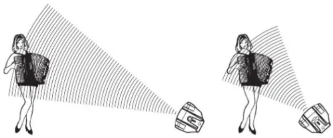
The dB300a is an ideal solution for stage monitoring and thanks to its unique design, two wedge monitor positions are possible. When placed on its side, with the high frequency horn facing to the left of the enclosure, the dB300a is tilted at a 30 degree angle, optimizing performance when used on a large stage. When placed on its side with the high frequency horn facing to the right of the enclosure, the dB300a is tilted at a 45 degree angle optimizing performance when used on smaller stages. In a large stage monitor system, several dB300a's can be daisy-chained together using the Line Output. In many instances (when using the dB300a as a monitor system) you may choose to use an external equalizer like the Samson S Curve 131 to increase the volume and reduce the chance of feedback. In this case be sure to set the HIGH and LOW EQ to the 12:00 or flat position.
natural_image
Illustration of two women projecting a camera with a target, showing perspective angles (no text or symbols)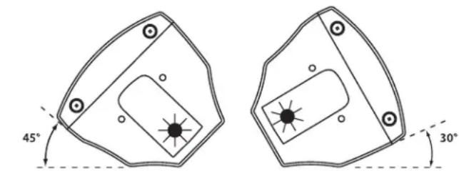
NEAR FIELD FAR FIELD
Operating the dB300a
Controls and Functions
The following section details each part of the dB300a's INPUT section including the MIC and LINE inputs, the two-band EQ, as well as the MIC and LINE LEVEL controls.

MIC LEVEL
The dB300a's MIC LEVEL controls the overall level of the microphone input. The MIC LEVEL control features an audio taper. Raise the MIC Level to adjust the volume of the microphone connected to the MIC input.
IMPORTANT NOTE: Be sure to keep the MIC LEVEL control all the way off if there is no microphone connected.

PEAK LED
The PEAK LED will illuminate RED when the dB300a's mic input is receiving a clipped signal. If the PEAK LED lights up, lower the MIC LEVEL control. Once the PEAK LED goes off, raise the level controls back up until just before the PEAK LED lights.

DYNAMIC PROTECTION
The AMP / CLIP LED is a dual color LED used to monitor the output of the dB300a's internal power amplifiers. When the unit is first powered on, the AMP / CLIP LED will light red (indicating the output relay is open). After the soft-start circuitry activates and the output relay closes, the AMP / CLIP will change to bright green indicating the unit is ready for operation. The LED will flash red on signal power peaks, while the green LED is still on. If there is a failure condition such as DC on the output, the output relay opens and the LED will switch to solid red, indicating a fault. If this happens, contact your authorized Samson Audio Service Center.

LINE LEVEL
The dB300a's LINE LEVEL controls the overall level of the LINE input and features an audio taper. Raise the LINE Level to adjust the volume of the signal connected to the LINE input.
Using the Equalizer Section
The dB300a input channels feature a 2-band equalizer allowing you to adjust the high and low frequencies independently. The channel's frequency response is flat when the knobs are in the "12:00" position.

LOW
Rotating the LOW knob towards the right will boost the bass frequencies at 100Hz by 12dB, and rotating it towards the left will cut the bass frequencies at 100Hz by 12dB.

HIGH
Rotating the HIGH knob towards the right will boost the treble frequencies at 10kHz by 12dB, and rotating it towards the left will cut the treble frequencies at 10kHz by 12dB.
Operating the dB300a
Controls and Functions - continued

LOW FILTER
The dB300a also incorporates a Low-cut FILTER which when engaged, will roll off the low frequency response of the cabinet beginning at 80Hz. The low cut FILTER is two pole, which means that the low frequency roll off will gradually cut more and more of the low frequencies (12dB per octave). When you press the FILTER switch in, the green LED will illuminate indicating that the Low-cut FILTER is engaged.

OUTPUT SWITCH
The Output switch is used to select
the signal that is sent to the Line Output. You can have either a parallel output directly from the Line input, or a mixed signal including the Mic and line inputs plus the EQ and limiter. When the switch is in the up position, the signal on the Line Output is exactly the same as the signal on the Line Input. When the switch is in the down position, the Line Output carries the MIX of the Mic and Line Inputs. If the Level controls, High and Low Equalizer and Filter are used, they will also affect the signal sent to the Line Output.
Input and Output Connectors

MIC XLR Input
The dB300a's microphone input accepts a standard low impedance (150-600 Ohms) input and the connection is made via a standard female XLR connector. The microphone input features a high quality, discrete transistor pre-amp providing transparency and extended dynamic range. The MIC input can work simultaneously with the LINE input so it is possible to use a microphone while playing alone with a keyboard that is plugged into the dB300a's LINE input. You can control the microphone input by using the MIC LEVEL control as described in the section below.

LINE OUTPUT
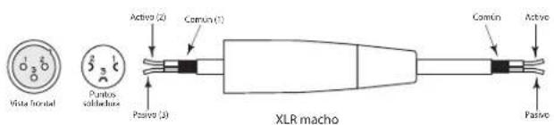
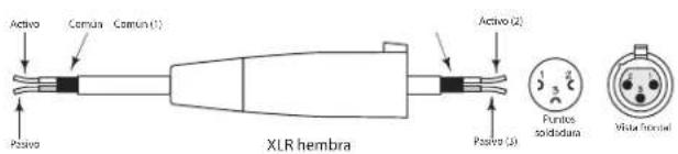
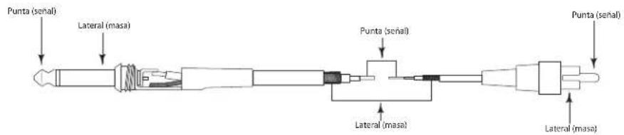
You can run several monitors by using the LINE OUTPUT to daisy-chain one dB300a to another. The LINE OUTPUT is a balanced output that, depending on the position of the OUTPUT switch, will have either a direct parallel output of the Line input, or the Mix of the Line and Mic input. For more information on the Output switch, see section 8 above. For more information on cables and wiring, see page 14 of this manual for a detailed wiring diagrams.

LINE Combo Balanced Input
For added convenience, the dB300a employs a Combo connector that accepts a standard XLR mic cable for balanced line level signals, or a standard 1/4" instrument cable for either balanced (TRS - TIP/RING/SLEEVE) or unbalanced (TS - TIP/SLEEVE) line level signals. The LINE input can work simultaneously with the Mic input so it is possible to use a microphone while playing alone with a keyboard that is plugged into the dB300a's LINE input. You can control the LINE input by using the LINE LEVEL control as described in the previous page. For more information on cable and wiring, see page 14 of this manual for a detailed wiring diagrams
Setting Up Your dB300a System
Using Speaker Stands
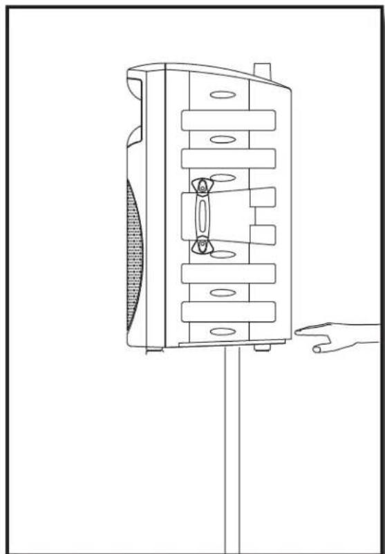
The dB300a enclosure features a standard 1 3/8", pole mount receptacle, which is compatible with speaker stands from a variety of manufacturers. Before installing the dB300a on a speaker stand, loosen the thumbscrew located on the bottom of the rear side of the enclosure. Once installed on the stand, be sure to tighten the thumbscrew to hold the speaker in place. Be careful not to over tighten the thumbscrew to avoid stripping the threads.
Stacking the dB300a
The dB300a enclosure incorporates gender mating stack feet and bumpers that allows you to stack one dB300a on top of another. When stacking the dB300a's, be certain that the rubber feet from the top unit are securely fastened into the bottom unit's stacking bumpers.
NOTE: DO NOT STACK dB300a's OVER TWO (2) TALL.
natural_image
Technical line drawing of a mechanical device with internal components and a hand pointing to it (no text or symbols)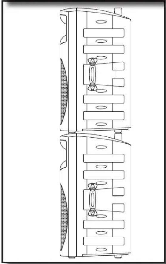
natural_image
Technical line drawing of a dual-chamber electronic device with internal components (no text or symbols)Setting Up Your dB300a System
Permanent Installation
The dB300a is a logical solution for many fixed installations in live sound venues, discos, schools, houses of worship, convention centers and airport terminals to name a few. The enclosure is extremely versatile for installation as it can be hung in several different positions by using the 4 Fly-points.
Hanging the dB300a is serious business and therefore licensed and insured professional sound contractors only should perform such an installation.
natural_image
Technical line drawing of a mechanical component with internal slots and mounting holes (no text or symbols)Using the Fly-points
IMPORTANT NOTE: Only licensed and insured professional sound contractors should install the dB300a using the Fly-points. Samson assumes no liability for any installation.
The dB300a features 4 Fly-points located in pairs on the top and bottom of the enclosure. By removing the installed screws, you will have access to the threaded inserts that are compatible with a variety of standard M6 hardware including that offered by ATM Flyware.
dB300a System Set-ups
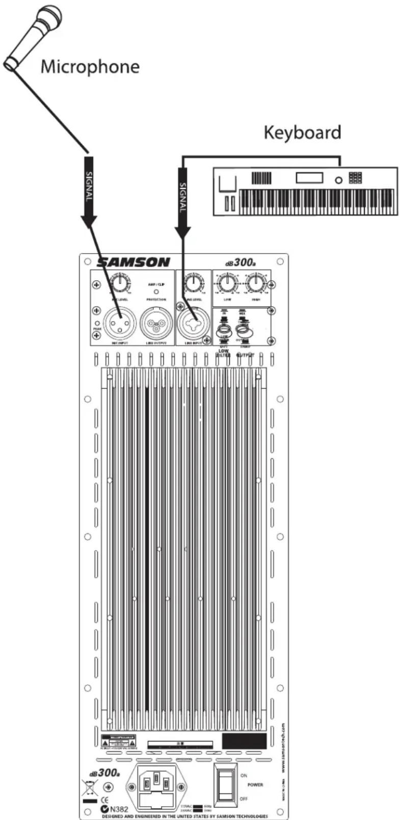
Compact Lounge PA for Two
This example shows a PA system set-up that can be used for a small club, at a ceremony or in a lounge, using a single dB300a for both a microphone and vocal. A separate signal is sent from the vocal microphone to the dB300a's Mic input, and from the keyboard to the dB300a's Line input. The individual Mic and Line level controls allow you to create a mix right on the dB300a. For further control, you can use the dB300a's two-band equalizer to boost or cut the highs and/or low frequencies adjusting the overall tonal contour of the system.
dB300a System Set-ups
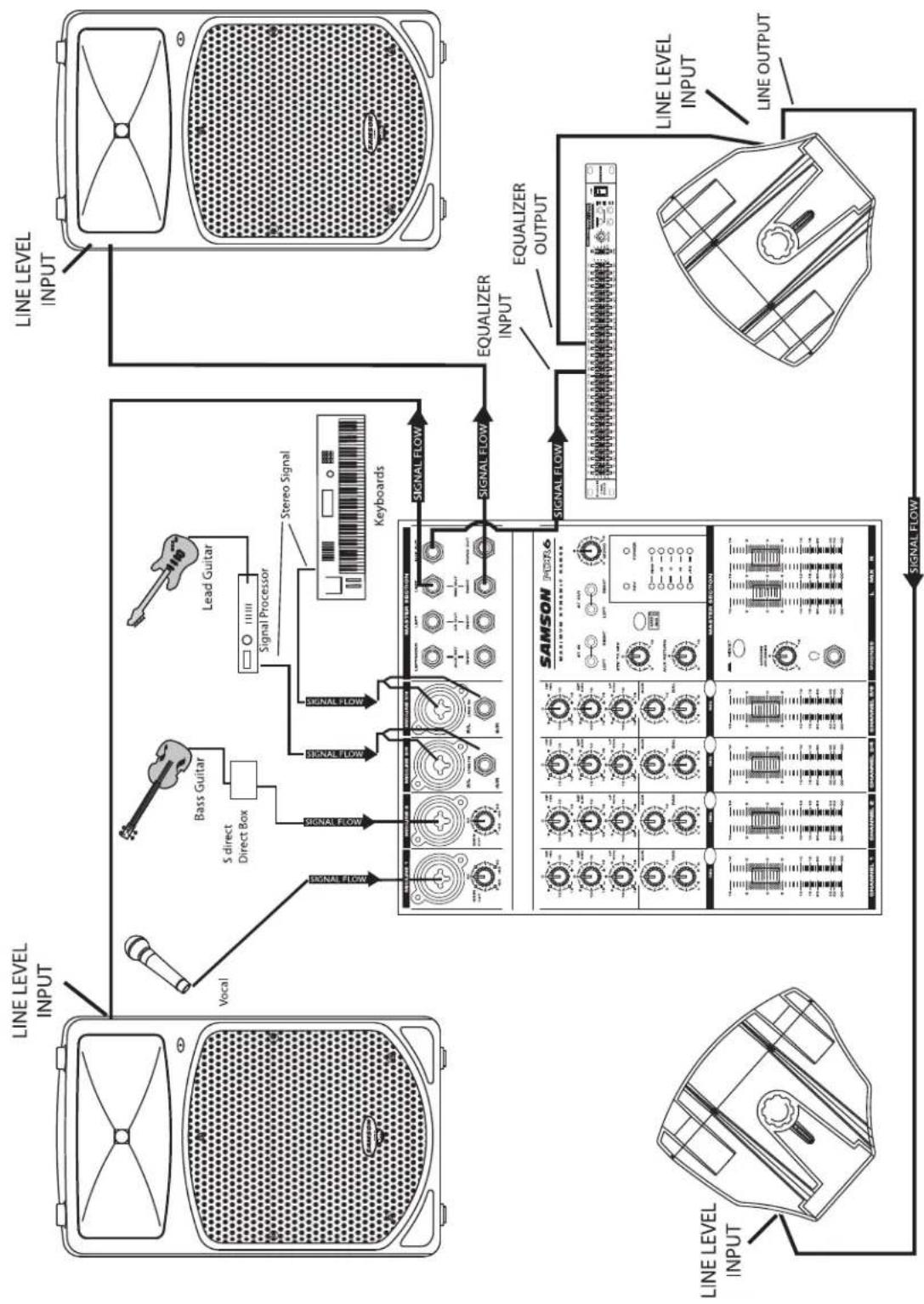
Live Band PA System With Monitors
flowchart
graph TD
    A["Line Level Input"] --> B["Vocal"]
    B --> C["S direct Direct Box"]
    C --> D["Bass Guitar"]
    D --> E["Lead Guitar"]
    E --> F["Signal Processor"]
    F --> G[" Stereo Signal "]
    G --> H["Keyboards"]
    H --> I["SIGNAL FLOW"]
    I --> J["EQUALIZER INPUT"]
    J --> K["SAMSON MODE"]
    K --> L["SIGNAL FLOW"]
    L --> M["EQUALIZER OUTPUT"]
    M --> N["SAMSON MODE"]
    N --> O["SIGNAL FLOW"]
    O --> P["Line Level Input"]
    P --> Q["SIGNAL FLOW"]
    Q --> R["Line LEVEL INPUT"]
    R --> S["SAMSON MODE"]
    S --> T["SIGNAL FLOW"]
    T --> U["EQUALIZER OUTPUT"]
    U --> V["SAMSON MODE"]
    V --> W["SIGNAL FLOW"]
    W --> X["EQUALIZER INPUT"]
    X --> Y["SAMSON MODE"]
    Y --> Z["SIGNAL FLOW"]
This example shows a typical PA system using mixer with a pair of dB300a's for the main left and right mix. A separate signal from the mixer's AUX/MONITOR bus is sent to two additional dB300a's placed in the tilt-back, wedge positions for use as floor monitors. In order to increase the output of the monitor system, the use of an external graphic equalizer like one of the Samson "D Class" or "S curve" series is highly recommended.
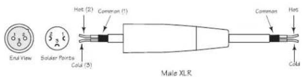
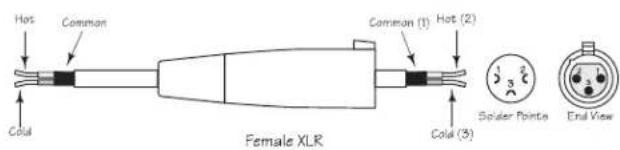
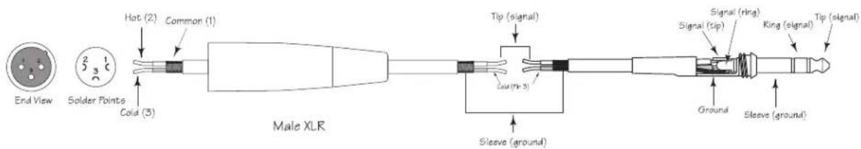
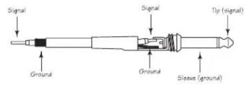
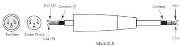
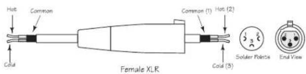
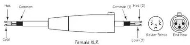
dB300a Wiring Guide
Connecting The dB300a
The are several ways to interface the dB300a to support a variety of applications. The dB300a features balanced inputs and outputs, so connecting balanced and unbalanced signals is possible.
Unbalanced 1/4" Connector
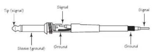
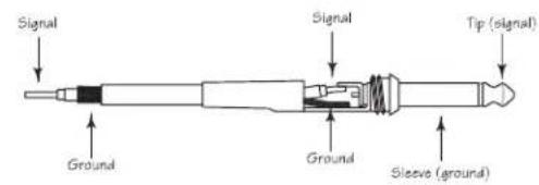
Balanced TRS 1/4" Connector
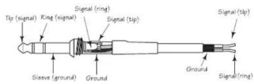
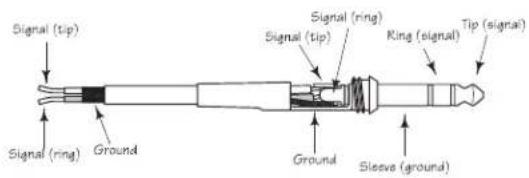
XLR to XLR Balanced
Unbalanced 1/4" Connector to RCA
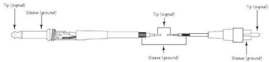
XLR to Balanced 1/4-Inch
Introduction
natural_image
Technical line drawing of a speaker grille with fan blade and base (no text or symbols)natural_image
Line drawing of a portable radio with a perforated grille and tripod base (no text or symbols)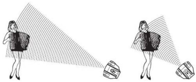
natural_image
Illustration of two women projecting a target with a flag, no text or symbols present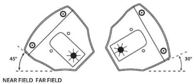

XLR/XLR symétrique
Einleitung
natural_image
Technical line drawing of a speaker with antenna and cover (no text or symbols)natural_image
Line drawing of a vintage desktop microphone with four tripod stand (no text or symbols)dB300a bedienen


Introducción
natural_image
Diagram of a speaker grille with antenna and base (no text or symbols)natural_image
Line drawing of a portable electronic device with a perforated grille and four tripod legs (no text or symbols)natural_image
Illustration of two women carrying bags with a magnified view of a bag (no text or symbols)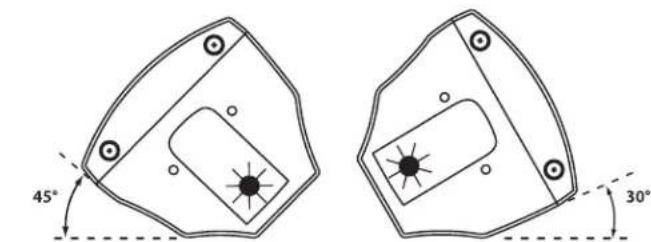
NEAR FIELD FAR FIELD
Manejo del dB300a
XLR a XLR balanceado
Conector de 6,3 mm no balanceado a RCA
natural_image
Diagram of a device with top and front views, showing a bow-shaped top panel and a textured base (no text or symbols)natural_image
Line drawing of a vintage-style portable radio with a perforated grille and tripod base (no text or symbols)natural_image
Illustration of two women projecting a target with a shaded area, no text or symbols present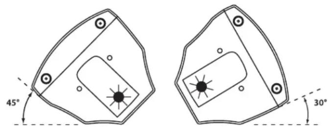
NEAR FIELD FAR FIELD
L'Uso dei dB300a
natural_image
Technical line drawing of a mechanical device with internal components and a hand pointing to it (no text or symbols)natural_image
Technical line drawing of a dual-chamber HVAC unit with ventilation slots and mounting brackets (no text or symbols)natural_image
Technical line drawing of a mechanical component with internal slots and mounting holes (no text or symbols)MB300U - "U mount" Bracket
The MB300U "U-bracket" mounting kit is used for ceiling and wall installations, allowing the dB300a to be mounted in a variety of positions. Either vertical or horizontal configurations can be used to achieve the desired sound coverage. The MB300U can also be used in conjunction with the MB300A array kit for creating hanging arrays of two to six speakers. For more information, please visit our web site at www.samsontech.com.
MB300U - Kit de "supports en U"
MB300U - "U-Bracket"
MB300U - "Staffa a U"
natural_image
Technical line drawing of a mechanical assembly with multiple views and mounting holes (no text or symbols)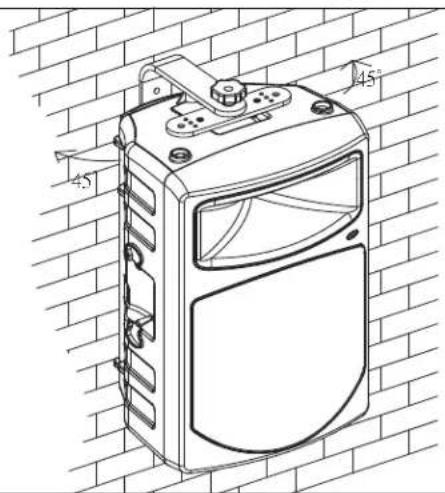
Optional Mounting Kits / Kits de fixation optionnels / Optionale Montage-Kits Kits opcionales de montaje /Kit di Montaggio Opzionali
MB300A - Array Kit
The MB300A array kit is used to create hanging arrays of two to six dB300a enclosures. Used in conjunction with the MB300U, arrays of 50° angles for tight coverage, or 60° angles for wide coverage, are possible. For more information, please visit our web site at www.samsontech.com.
B300A - Kit de suspension
natural_image
Diagram showing two identical electronic devices with labeled ports and connectors, connected by an arrow indicating transformation (no text or symbols present)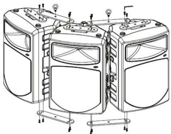
natural_image
Technical line drawing of a multi-panel electronic device with mounting brackets and wiring (no text or symbols)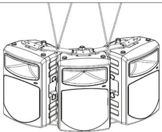
natural_image
Technical line drawing of a three-tiered mechanical device with mounting holes and internal compartments (no text or symbols)Microphone Balanced XLR
Line Balanced Combo XLR/Line
Outputs
Extension Balanced XLR
Controls
Mic Level Rotary
Line Level Rotary
Low EQ Rotary Center Detent, +/-12dB @100Hz
High-EQ Rotary Center Detent, +/-12dB @ 10kHz
Low Filter Switch Push Switch, High Pass (low-cut) 12dB per octave @80Hz
Output Switch Push Switch, Selects Mix or Thru for Line Output Connector
Power Rating:
Low Frequency 250 Watt RMS
High Frequency 50 Watt RMS
Frequency Response:
Crossover Frequency:
LF Driver:
HF Driver:
Mounting:
Stand
Fly Points 4
Stacking
Weight:
Dimensions:
60 Hz - 24 kHz ± 3 dB
2.3 kHz, 3 pole (18 dB Per Octave)
12" heavy-duty bass transducer, 3" voice coil (Kapton Former), 50
oz. barium ferrite magnet
1.75" titanium compression driver, edge-wound copper voice coil,
64 oz. magnet structure
Integral 1 3/8" Pole Mount Receptacle,
Large, gender mating stacking bumpers
47lbs. (21.4 kg)
Specifications are subject to change without notice.
Notes
Samson Technologies Corp.
45 Gilpin Avenue
Hauppauge, New York 11788-8816
Phone: 1-800-3-SAMSON (1-800-372-6766)
Fax: 631-784-2201
www.samsontech.com

- Owners Manual
- Safety Instructions/Consignes de sécurité/Sicherheitsvorkehrungen
- WARNING
- CAUTION
- Important Safety Instructions
- Table of Contents
- ENGLISH
- FRANÇAIS
- dB300a Features
- dB300a Layout
- dB300a Front View Layout
- dB300a Rear Panel Layout
- dB300a REAR PANEL
- Quick Set-Up
- Using a Microphone
- Using a Line Level Signal
- Positioning the dB300a
- Microphone Positioning - How to Reduce Feedback
- Speaker Placement
- Using the dB300a as a Floor Monitor
- Operating the dB300a
- Controls and Functions
- MIC LEVEL
- PEAK LED
- DYNAMIC PROTECTION
- LINE LEVEL
- Using the Equalizer Section
- LOW
- HIGH
- Controls and Functions - continued
- LOW FILTER
- OUTPUT SWITCH
- Input and Output Connectors
- MIC XLR Input
- LINE OUTPUT
- LINE Combo Balanced Input
- Setting Up Your dB300a System
- Using Speaker Stands
- Stacking the dB300a
- Permanent Installation
- Using the Fly-points
- dB300a System Set-ups
- Compact Lounge PA for Two
- dB300a Wiring Guide
- Connecting The dB300a
- Introduction
- Einleitung
- dB300a bedienen
- Introducción
- Manejo del dB300a
- L'Uso dei dB300a
- MB300U - "U mount" Bracket
- MB300U - Kit de "supports en U"
- MB300U - "U-Bracket"
- MB300U - "Staffa a U"
- Optional Mounting Kits / Kits de fixation optionnels / Optionale Montage-Kits Kits opcionales de montaje /Kit di Montaggio Opzionali
- MB300A - Array Kit
- B300A - Kit de suspension
- Notes
Brand : SAMSON
Model : dB300a
Category : Loudspeaker