
PlasmaSync 42XC10 - Television NEC - Free user manual and instructions
Find the device manual for free PlasmaSync 42XC10 NEC in PDF.
| Brand | NEC |
| Model | PlasmaSync 42XC10 |
| Product type | Plasma display TV |
| Screen size (diagonal) | 42 inches (approx. 107 cm) |
| Display technology | Plasma |
| Native resolution | 1024 x 768 pixels |
| Video inputs | VGA (mini D-sub 15), DVI, HDMI (DVD/HD3), S-Video, Composite video, Component (DVD/HD1 and DVD/HD2) |
| Audio inputs | 3 audio inputs (AUDIO1, AUDIO2, AUDIO3) for stereo signals |
| Audio output | Connector for external speakers (8W + 8W at 8 ohms) |
| Power supply | 100-240 V AC, 50/60 Hz |
| Included accessories | Remote control, AA batteries, power cord, user manual (CD-ROM), quick start guide, cable ties, cover for main power switch |
| Special functions | Digital zoom, PIP (picture-in-picture), split screen (side by side), remote ID, screen saver, pointer |
| Remote control | Infrared remote control with AA batteries, range up to 7 meters, 30 degree angle |
| Control interface | RS-232C (input and output) for external control |
| Mounting | VESA compatible (M8 screws), for wall or ceiling mounting |
| Safety | Important safety instructions: do not open, avoid moisture, unplug during storms |
| Screen maintenance | Wipe with a soft dry cloth; do not use chemical cleaners |
| Cabinet maintenance | Clean with a soft cloth moistened with water and mild detergent, then wipe dry |
| Repairability | Refer all repairs to qualified personnel; no user-repairable parts |
| Operating environment | Temperature: 0 to 40°C; relative humidity: < 80% (non-condensing) |
| Image retention | Avoid displaying still images for long periods; use screen saver |
Frequently Asked Questions - PlasmaSync 42XC10 NEC
User questions about PlasmaSync 42XC10 NEC
0 question about this device. Answer the ones you know or ask your own.
Ask a new question about this device
Download the instructions for your Television in PDF format for free! Find your manual PlasmaSync 42XC10 - NEC and take your electronic device back in hand. On this page are published all the documents necessary for the use of your device. PlasmaSync 42XC10 by NEC.
USER MANUAL PlasmaSync 42XC10 NEC
PykoBoCTBO no haaypa6oTbI
Baslangic Kilavuzu
ANVÄNDARHANDLEDNING
(Apenas no CD-ROM)
Kullanim Kilavuzu
(endast pa CD-ROM)
- Plasma Monitor
- Remote control and AA Batteries
- Power cord
- Users Manual (CD-ROM)
- Start Up Guide (Paper / CD-ROM)
- Main Power Switch cover and screw
- Cable clamps
Table of Contents
Important Safety Instructions. English-1
Important Information. English-2
Safety Precautions and Maintenance. English-3
Recommended Use English-4
Installation
Optional Stands/Mounts. English-6
Mounting Location. English-6
Mounting on Ceiling. English-7
Maintenance, Orientation, Cable Management . English-7
Using the Remote. English-8
Part Names and Functions
Control Panel. English-9
Terminal Panel. English-10
Remote Control. English-11
Power, Display, Digital Zoom, Pointer, Main Power Switch Cover English-12
Remote Control ID. English-13
On-Screen Display (OSD)
Using the OSD. English-14
OSD. English-15
Troubleshooting. English-18
Specifications
42XC10. English-19
50XC10 English-20
60XC10 English-21
Supported Resolutions
42XC10. English-22
50XC10 English-24
60XC10 English-26
Pin Assignment. English-28
Important Safety Instructions
Read Before Operating Equipment.
- Read these instructions.
- Keep these instructions.
- Heed all warnings.
- Follow all instructions.
- Do not use this apparatus near water.
- Clean only with a dry cloth.
- Do not block any of the ventilation openings. Install in accordance with the manufacturer's instructions.
- Do not install near any heat sources such as radiators, heat registers, stoves, or other apparatus (including amplifiers) that produce heat.
- Do not defeat the safety purpose of the polarized or grounding-type plug. A polarized plug has two blades with one wider than the other. A grounding type plug has two blades and third grounding prong The wide blade or third prong are provided for your safety. If the provided plug does not fit into your outlet, consult an electrician for replacement of the obsolete outlet.
- Protect the power cord from being walked on or pinched particularly at plugs, convenience receptacles, and the point where they exit from the apparatus.
- Only use attachments/accessories specified by the manufacturer
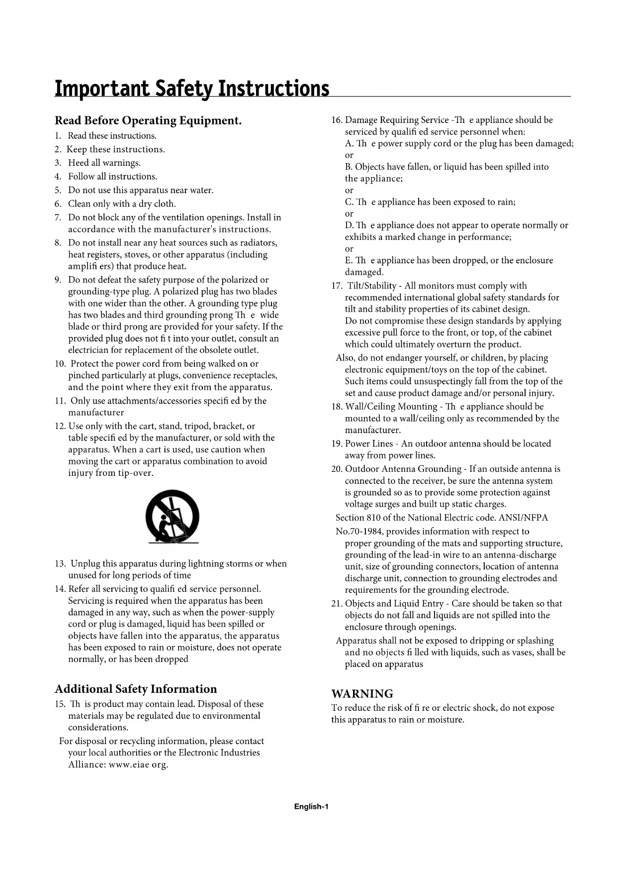
- Use only with the cart, stand, tripod, bracket, or table specified by the manufacturer, or sold with the apparatus. When a cart is used, use caution when moving the cart or apparatus combination to avoid injury from tip-over.

- Unplug this apparatus during lightning storms or when unused for long periods of time
- Refer all servicing to qualified service personnel. Servicing is required when the apparatus has been damaged in any way, such as when the power-supply cord or plug is damaged, liquid has been spilled or objects have fallen into the apparatus, the apparatus has been exposed to rain or moisture, does not operate normally, or has been dropped
Additional Safety Information
- Th is product may contain lead. Disposal of these materials may be regulated due to environmental considerations.
For disposal or recycling information, please contact your local authorities or the Electronic Industries Alliance: www.eiae.org.
- Damage Requiring Service -Th e appliance should be serviced by quali ed service personnel when:
A. The power supply cord or the plug has been damaged; or
B. Objects have fallen, or liquid has been spilled into the appliance; or
C. The appliance has been exposed to rain; or
D. The appliance does not appear to operate normally or exhibits a marked change in performance; or
E. The appliance has been dropped, or the enclosure damaged.
- Tilt/Stability - All monitors must comply with recommended international global safety standards for tilt and stability properties of its cabinet design.
Do not compromise these design standards by applying excessive pull force to the front, or top, of the cabinet which could ultimately overturn the product.
Also, do not endanger yourself, or children, by placing electronic equipment/toys on the top of the cabinet. Such items could unsuspectingly fall from the top of the set and cause product damage and/or personal injury.
- Wall/Ceiling Mounting - The appliance should be mounted to a wall/ceiling only as recommended by the manufacturer.
- Power Lines - An outdoor antenna should be located away from power lines.
- Outdoor Antenna Grounding - If an outside antenna is connected to the receiver, be sure the antenna system is grounded so as to provide some protection against voltage surges and built up static charges.
Section 810 of the National Electric code. ANSI/NFPA
No.70-1984, provides information with respect to proper grounding of the mats and supporting structure, grounding of the lead-in wire to an antenna-discharge unit, size of grounding connectors, location of antenna discharge unit, connection to grounding electrodes and requirements for the grounding electrode.
- Objects and Liquid Entry - Care should be taken so that objects do not fall and liquids are not spilled into the enclosure through openings.
Apparatus shall not be exposed to dripping or splashing and no objects filled with liquids, such as vases, shall be placed on apparatus
WARNING
To reduce the risk of fire or electric shock, do not expose this apparatus to rain or moisture.
WARNING

TO PREVENT FIRE OR SHOCK HAZARDS, DO NOT EXPOSE THIS UNIT TO RAIN OR MOISTURE. DO NOT USE THIS UNIT'S POLARIZED PLUG WITH AN EXTENSION CORD RECEPTACLE OR OTHER OUTLETS UNLESS THE PRONGS CAN BE FULLY INSERTED.

REFRAIN FROM OPENING THE CABINET AS THERE ARE HIGH VOLTAGE COMPONENTS INSIDE. REFER SERVICING TO QUALIFIED SERVICE PERSONNEL.
CAUTION
CAUTION: TO REDUCE THE RISK OF ELECTRIC SHOCK, MAKE SURE POWER CORD IS UNPLUGGED FROM WALL SOCKET. TO FULLY DISENGAGE THE POWER TO THE UNIT, PLEASE DISCONNECT THE POWER CORDFROM THE AC OUTLET. DO NOT REMOVE COVER (OR BACK). NO USER SERVICEABLE PARTS INSIDEREFER SERVICING TO QUALIFIED SERVICE PERSONNEL.

This symbol warns user that uninsulated voltage within the unit may have sufficient magnitude to cause electric shock. Therefore, it is dangerous to make any kind of contact with any part inside this unit.

This symbol alerts the user that important literature concerning the operation and maintenance of this unit has been included. Therefore, it should be read carefully in order to avoid any problems.
CAUTION: Please use the power cord provided with this display in accordance with the table below. If a power cord is not supplied with this equipment, please contact your supplier. For all other cases, please use a power cord that matches the AC voltage of the power outlet and has been approved by and complies with the safety standard of your particular country.
| Plug Type | North America | European Continental | U.K. | Chinese | Japanese |
| Plug Shape | |||||
| Country | U.S.A./Canada | EU (except U.K.) | U.K. | China | Japan |
| Voltage | 120* | 230 | 230 | 220 | 100 |
*When operating the PlasmaSync monitor with its AC 125-240V power supply, use a power supply cord that matches the power supply voltage of the AC power outlet being used.
Canadian Department of
Communications Compliance Statement
DOC: Th is Class B digital apparatus meets all requirements of the Canadian Interference-Causing Equipment Regulations.
FCC Information
- Use the attached specified cables with the P426Y3(P42XC10), P506Y4(P50XC10) or P606Y5(P60XC10) color monitor so as not to interfere with radio and television reception.
(1) Please use the supplied power cord or equivalent to ensure FCC compliance.
(2) Please use shielded video signal cable, 15-pin mini D-SUB to 15-pin mini D-SUB with ferrite cores on both ends (not included).
- Th is equipment has been tested and found to comply with the limits for a Class B digital device, pursuant to part 15 of the FCC Rules. Th es e limits are designed to provide reasonable protection against harmful interference in a residential installation. This equipment generates, uses, and can radiate radio frequency energy, and, if not installed and used in accordance with the instructions, may cause harmful interference to radio communications. However, there is no guarantee that interference will not occur in a particular installation. If this equipment does cause harmful interference to radio or television reception, which can be determined by turning the equipment off and on, the user is encouraged to try to correct the interference by one or more of the following
measures:
Reorient or relocate the receiving antenna.
- Increase the distance between the equipment and receiver.
- Connect the equipment into an outlet on a circuit different from that to which the receiver is connected.
- Consult your dealer or an experienced radio/TV technician for help.
If necessary, the user should contact the dealer or an experienced radio/ television technician for additional suggestions. The user may find the following booklet, prepared by the Federal Communications Commission, helpful: "How to Identify and Resolve Radio-TV Interference Problems." This booklet is available from the U.S. Government Printing Office, Washington, D.C., 20402, Stock No. 004-000-00345-4.
WARNING
This product equipped with a three-wire grounding (earthed) plug - a plug that has a third (grounding) pin. This plug only fits a grounding-type power outlet. If you are unable to insert the plug into an outlet, contact a licensed electrician to replace the outlet with a properly grounded one. Do not defeat the safety purpose of the grounding plug.
Safety Precautions and Maintenance
Safety Precautions and Maintenance
FOR OPTIMUM PERFORMANCE, PLEASE NOTE THE FOLLOWING WHEN SETTING UP AND USING THE MONITOR:
The plasma display's panel is made up of fine picture elements (cells), of which more than 99.99 percent are active cells. Some cells may not produce light or remain constantly lit. For safe operation and to avoid damaging the unit, read carefully and observe the following instructions.
DO NOT OPEN THE MONITOR. There are no user-serviceable parts inside and opening or removing covers may expose you to dangerous shock hazards or other risks. The manufacturer is not liable for any bodily harm or damage caused if unqualified persons attempt service or open the back cover. Refer all servicing to qualified service personnel.
- Do not spill any liquids into the cabinet or use your monitor near water.
- Do not insert objects of any kind into the cabinet slots, as they may touch dangerous voltage points, which can be harmful or fatal or may cause electric shock, fire or equipment failure.
- Do not bend, crimp or otherwise damage the power cord.
- Do not place any heavy objects on the power cord.
- Damage to the cord may cause shock or fire.
- Do not place this product on a sloping or unstable cart, stand or table, as the monitor may fall, causing serious damage to the monitor.
- Do not use in a moving vehicle, as the unit could drop or topple over and cause injuries.
- The power cable connector is the primary means of detaching the system from the power supply. The monitor should be installed close to a power outlet that is easily accessible.
- Th is equipment shall be connected to a MAIN outlet with a protective earth-ground connection. Do not place any objects onto the monitor and do not use the monitor outdoors.
- Do not use this unit's polarized plug with an extension cord or with outlets unless the prongs can be inserted fully.
- The power supply cord you use must have been approved by and comply with the safety standards of your country. (Type H05VV-F 3G 1mm² should be used in Europe)
- In UK, use a BS-approved power cord with molded plug having a black (13A) fuse installed for use with this monitor.
- Use only with 100V to 240V50Hz / 60Hz AC power supply. Continued operation at line voltages greater than 100V to 240V AC will shorten the life of the unit, and might even cause a fire hazard.
- Unplug the power cord during electrical storms or when the unit will not be in use for a long period.
- Do not use monitor in high temperature, humid, dusty, or oily areas.
- Do not cover vent on monitor.
- Clean plasma ventilation areas using a vacuum cleaner with a soft brush nozzle attachment.
- To ensure proper ventilation, cleaning the ventilation areas must be carried out monthly. More frequent cleaning may be necessary depending on the environment in which the plasma monitor is installed.
- Allow adequate ventilation around the monitor so that heat can properly dissipate. Do not block ventilated openings or place the monitor near a radiator or other heat sources. Do not put anything on top of monitor.
- Handle with care when transporting. Save packaging for transporting.
- As is the case with any phosphor-based display (like a CRT monitor, for example) light output will gradually decrease over the life of a Plasma Display Panel.
- To avoid sulfurization it is strongly recommended not to place the unit in a dressing room in a public bath or hot spring bath.

Immediately unplug your monitor from the wall outlet and refer servicing to qualified service personnel under the following conditions:
- When the power supply cord or plug is damaged.
- If liquid has been spilled on, or objects have fallen into the monitor.
- If the monitor has been exposed to rain or water.
- If the monitor has been dropped or the cabinet damaged.
- If the monitor does not operate normally by following operating instructions.
CAUTION
CORRECT PLACEMENT AND ADJUSTMENT OF THE MONITOR CAN REDUCE EYE, SHOULDER AND NECK FATIGUE. CHECK THE FOLLOWING WHEN POSITIONING THE MONITOR:
- For optimum performance, allow 20 minutes for warm-up.
- Rest your eyes periodically by focusing on an object at least 5 feet away. Blink oft en.
- Position the monitor at a 90 degree angle to windows and other light sources to minimize glare and reflections.
- Clean the monitor surface with a lint-free, nonabrasive cloth. Avoid using any cleaning solution or glass cleaner.
- Adjust the monitor's brightness and contrast controls to enhance readability.
- Get regular eye checkups.
Ergonomics
To realize the maximum ergonomic benefits, we recommend the following:
- Use the preset Size and Position controls with standard signals.
- Use the preset Color Setting.
- Do not use primary color blue on a dark background, as it is difficult to see and may produce eye fatigue due to insufficient contrast.
- Th is equipment is not for use at video display work station according to Bildscharb V.
For more detailed information on setting up a healthy work environment, refer to the following document:
American National Standard for Human Factors Engineering of Visual Display Terminal Workstations ANSI-HFS Standard No. 100-1988
Published by:
The Human Factors and Ergonomics Society P.O.Box 1369, Santa Monica, California 90406.
Cleaning the Panel
- When the panel becomes dusty or dirty, wipe gently with soft cloth.
- Do not rub the panel with coarse material.
- Do not apply pressure to the surface.
- Do not use OA cleaner. OA cleaner will cause deterioration or discolor the surface.
Cleaning the Cabinet
- Unplug the power supply.
- Gently wipe the cabinet with a soft cloth.
- To clean the cabinet, dampen the cloth with a neutral detergent and water, wipe the cabinet and follow with a dry cloth.
NOTE: The surface of the cabinet is composed of many types of plastic.
DO NOT clean with benzene thinner, alkaline detergent, alcoholic system detergent, glass cleaner, wax, polish cleaner, soap powder, or insecticide. Rubber or vinyl should not be in contact with the cabinet for an extended period of time. The est types of fluids and materials can cause the paint to deteriorate, crack or peel.
CLEANING THE VENT HOLES
- Clean plasma ventilation areas using a vacuum cleaner with a soft brush nozzle attachment.
- To ensure proper ventilation, cleaning the ventilation areas must be carried out monthly. More frequent cleaning may be necessary depending on the environment in which the plasma monitor is installed.
To avoid or minimize image retention:
Like all phosphor-based display devices and all other gas plasma displays, plasma monitors can be susceptible to image retention under certain circumstances. Certain operating conditions, such as the continuous display of a static image over a prolonged period of time, can result in image retention if proper precautions are not taken. To protect your investment in this plasma monitor, please adhere to the following guidelines and recommendations for minimizing the occurrence of image retention:
- Always enable and use your computer's screen saver function during use with a computer input source.
- Display a moving image whenever possible.
- Change the position of the menu display from time to time.
- Always power down the monitor when you are finished using it.
To reduce the likelihood of image retention from long-term use:
- Lower the Brightness and Contrast levels as much as possible without impairing image readability.
- Display an image with many colors and color gradations (i.e. photographic or photo-realistic images).
- Create image content with minimal contrast between light and dark areas. Use complementary or pastel colors whenever possible.
- Avoid displaying images with few colors and distinct, sharply defined borders between colors.
Plasma monitor driving sound
- Th e panel of the Plasma monitor is composed of extremely fine pixels and these pixels emit light according to received video signals. Th is principle may cause you to hear a buzz or electrical hum coming from the Plasma monitor. Also note that the rotation speed of the cooling fan motor increases when the ambient temperature of the Plasma monitor becomes high. You may hear the sound of the motor at that time.
NOTE: The following items are not covered by the warranty.
- Image retention
- Panel generated sound. Examples: Fan motor and electrical noises circuit humming /glass panel buzzing.
OPERATING ENVIRONMENT
Operating environment temperature and humidity: 0^ to +40^ (+32^ to +104^) ; less than 80% RH (cooling vents not blocked) Do not install this unit in a poorly ventilated area, or in locations exposed to high humidity or direct sunlight (or strong artifi cial light)
WARNING
Not for use in a computer room as defined in the Standard for the Protection of Electronic Computer/Data Processing Equipment ANSI/NFPA 75.
NOTE: Please use shielded video signal cable, 15-pin mini D-SUB to 15-pin mini D-SUB with ferrite cores on both ends (not included).
Using Optional Stand/Mounts
An optional stand or mounting apparatus can be installed either while the unit is in the upright position or while the unit is face-down.
To install the stand while in the upright position, lower the monitor onto to the feet as shown (Figure 1). Use the handles to support the display while lowering the support holes underneath the display onto the feet.
If stand or mounting apparatus is to be installed while the unit is face-down (Figure 2), be sure to lay the protective sheet (the foam sheet that the unit was wrapped in) underneath the unit on order to prevent damage to the screen.
Th is unit must be used with a stand or some type of mounting apparatus. Th is unit is not designed for use without additional support.
- For correct Installation and Mounting it is recommended to use a trained, authorized dealer.
- Failure to follow correct mounting procedures could result in damage to the unit or to the installer.
- Product warranty does not cover damage caused by improper installation.
CAUTION:
- To install, follow those instructions included with the stand or mounting apparatus. Use only those devices recommended by the manufacturer.
- Make sure to install stand or mounting apparatus to the unit while on a surface that is strong and stable enough to support the weight of the unit, such as a floor or sturdy table.
- Use the specified clasps for installation.
Take necessary steps to prevent the unit from tipping or falling.
Mounting Location
The ceiling and wall must be strong enough to support the monitor and mounting accessories.
DO NOT install in locations where a door or gate can hit the unit.
DO NOT install in areas where the unit will be subjected to strong vibrations and dust.
DO NOT install near where the main power supply enters the building.
DO NOT install in where people can easily grab and hang onto the unit or the mounting apparatus.
- When mounting in an enclosure or in a recessed area, as in a wall, leave at least 2 inches (50mm) of space between the monitor and the wall for proper ventilation (Figure 3).
- Allow adequate ventilation or provide air conditioning around the monitor, so that heat can properly dissipate away from the unit and mounting apparatus.
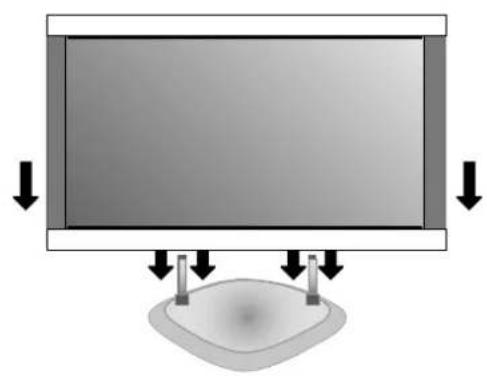
Figure 1
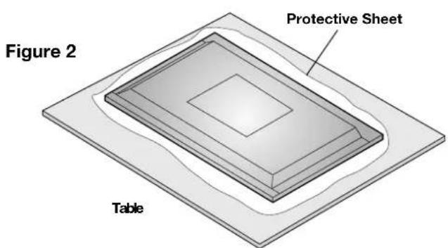
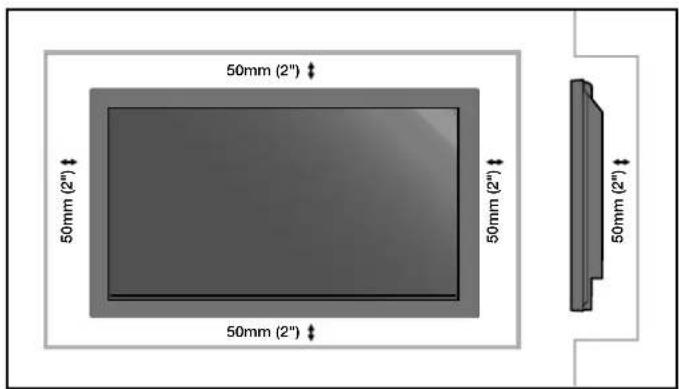
Figure 3
Mounting on Ceiling
- Ensure that the ceiling is sturdy enough to support the weight of the unit and the mounting apparatus over time, against earthquakes, unexpected vibrations, and other external forces.
- Be sure the unit is mounted to a solid structure within the ceiling, such as a support beam. Secure the monitor using bolts, spring lock washers, washer and nut.
- DO NOT mount to areas that have no supporting internal structure. DO NOT use wood screws or anchor screws for mounting. DO NOT mount the unit to trim or to hanging fixtures.
Maintenance
- Periodically check for loose screws, gaps, distortions, or other problems that may occur with the mounting apparatus. If a problem is detected, please refer to qualified personnel for service.
- Regularly check the mounting location for signs of damage or weakness that may occur over time.
Please note the following when mounting on wall or ceiling.
- When using mounting accessories other than those that are NEC approved, they must comply with the VESA-compatible (FDMlv1) mounting method.
- NEC strongly recommends using size M8 screws (16mm + thickness of bracket in length). If using screws longer than 16mm, check the depth of the hole.(Recommended Fasten Force: 1125 - 1375N·cm) NEC recommends mounting interfaces that comply with UL1678 standard in North America.
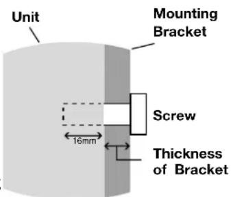
Screw length should equal depth of hole (16mm) + the thickness of mounting bracket.
Cable Management
To conveniently manage cables, use the cable clamps provided to bundle the power cord together with the signal and audio cables at the back of the display.
To attach cable clamps:
- Attach the cable clamps to the display. Insert the anchor of the clamp into the hole on the back of the display. There are 4 cable clamps and 4 clamp holes on the unit.
- After the cable clamp is positioned on the display, wrap the end around the cables. Place the end of the clamp into the slot near the anchor. Pull until cables are snug.
Clamps are designed to stay in place. Once in position, they will be difficult to remove.
- Cables can be routed to the right or left of the clamp. Use the beaded bands to secure the cables together along their length. Make sure the cables are fully supported.
To detach clamps:
Using pliers, twist the clamp 90 degrees and pull outward. It is possible that the clamp can weaken over time and removing it may cause damage to the clamp.

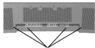
Holes for Clamp anchors

Orientation
DO NOT use this monitor in the portrait position. Doing so may cause failure and void the warranty.

Using the Remote:
Install the remote control batteries.
The remote control is powered by AA batteries. To install or replace batteries:
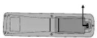
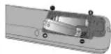

A. Press and slide to open the cover.
B. Align the batteries according to the (+) and (-) indications inside the case.
C. Replace the cover.
CAUTION: Incorrect usage of batteries can result in leaks or bursting. NEC recommends the following battery use:
- Place "AA" size batteries matching the (+) and (-) signs on each battery to the (+) and (-) signs of the battery compartment.
- Do not mix battery brands.
- Do not combine new and old batteries, or mix brands.
Th is can shorten battery life or cause liquid leakage of batteries. - Remove dead batteries immediately to prevent battery acid from leaking into the battery compartment.
- Do not touch exposed battery acid, it may injure skin.
- Do not drop or mishandle the remote.
- Do not get the remote control wet. If the remote does get wet, wipe dry immediately.
- Avoid excessive heat and humidity.
- Do not dispose of batteries in fire.
- Please follow government regulations or public environmental rules that apply in your country/area when disposing of used batteries.
- When replacing, use only conventional nonrechargeable alkaline or manganese batteries.
- There is a risk of explosion if batteries are replaced incorrectly.
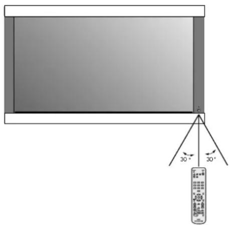
Operating Range for the Remote Control
Point the top of the remote control toward the monitor's remote sensor while pressing buttons. The remote control can be used from the front of the monitor at a maximum distance of 7m / 23 ft. from the front of the Plasma monitor's remote control sensor. The maximum horizontal and vertical angle for use of the remote is 30 degrees within a distance of 3.5m / 11.5 ft.
CAUTION
The remote control may not function when direct sunlight or strong illumination strikes the remote control sensor of the Plasma monitor, or when there is an object in the path of the sensor.
Handling the Remote Control
Do not open the remote control other than to install batteries. Do not allow water or other liquid to splash onto the remote control. If the remote control gets wet, wipe it dry immediately.
Avoid exposure to heat and steam.
NOTE: If you do not intend to use the Remote Control for a long period of time, remove the batteries.

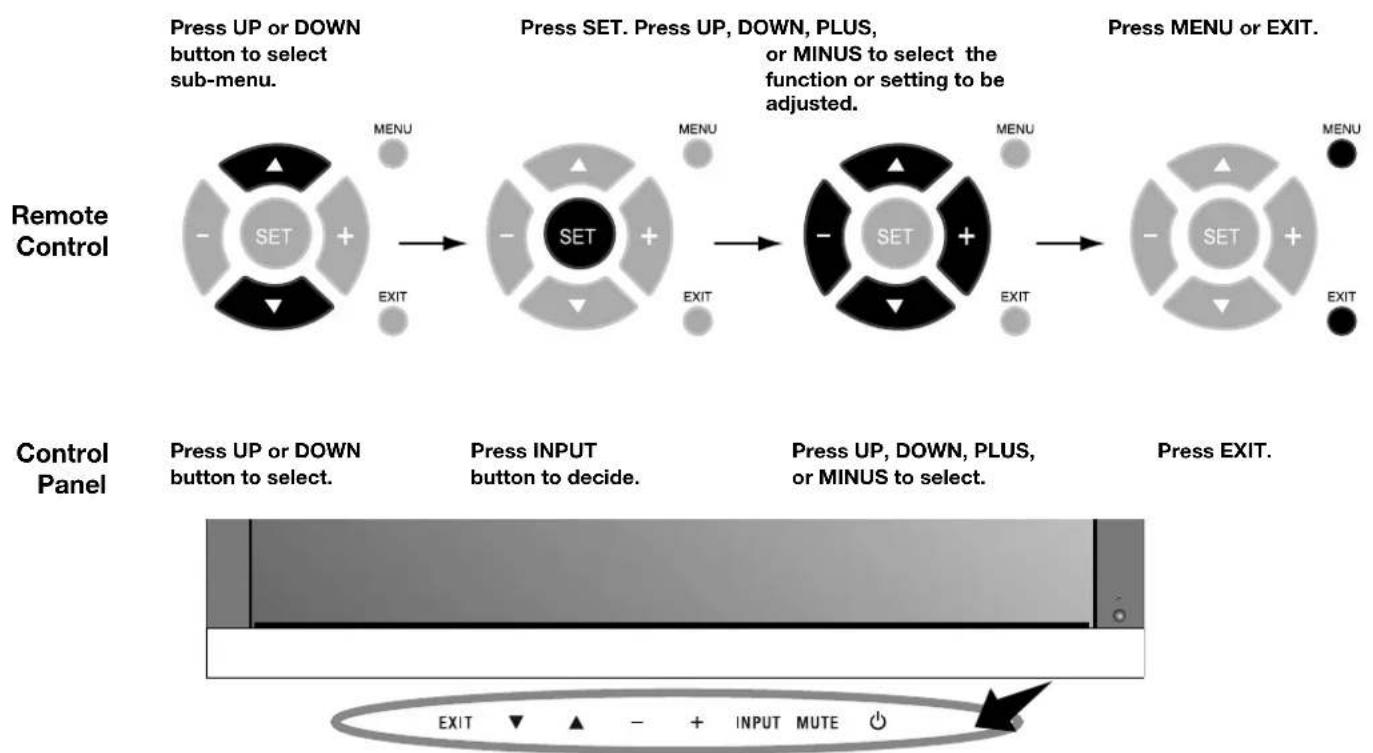
Control Panel
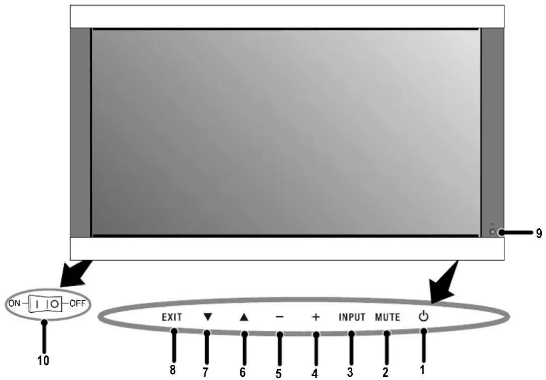
1) POWER
Switches the power on/standby.
2) MUTE
Switches the audio mute ON/OFF.
3) INPUT
Switches between input sources.
Acts as SET button within the OSD menu.
4) PLUS (+)
Increases the setting adjustment within OSD menu.
5) MINUS (-)
Decreases the setting adjustment within OSD menu.
6) UP
Increases the volume level when the OSD is off.
Moves area up to select which setting to is to be adjusted
within OSD menu.
7) DOWN
Decreases the volume level when the OSD is off.
Moves down to select which setting is to be adjusted within
OSD menu.
8) EXIT
Activates the OSD menu when the OSD menu is off. Exits from the current menu being displayed to the previous menu within the OSD.
9) Remote control sensor and Power indicator
Receives the signal when using the wireless remote control.
Glows green when the monitor is active. Glows red when the monitor is in Standby mode. Glows Amber when the monitor is in POWER SAVE mode.
A red blinking Power indicator means that the monitor has detected a failure. Contact qualifi ed personnel in case of failure.
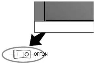
10) Main Power Switch
Seesaw switch to turn the main power on/off.
| Mode Status | indicator light |
| Power On Green | |
| Standby Red | |
| Power save Amber | |
| Diagnosis (Detecting failure) | Red blinking |
NOTE:
The POWER button does not completely turn off the display. Use the Main Power Switch to completely turn off the display.
Part Names and Functions
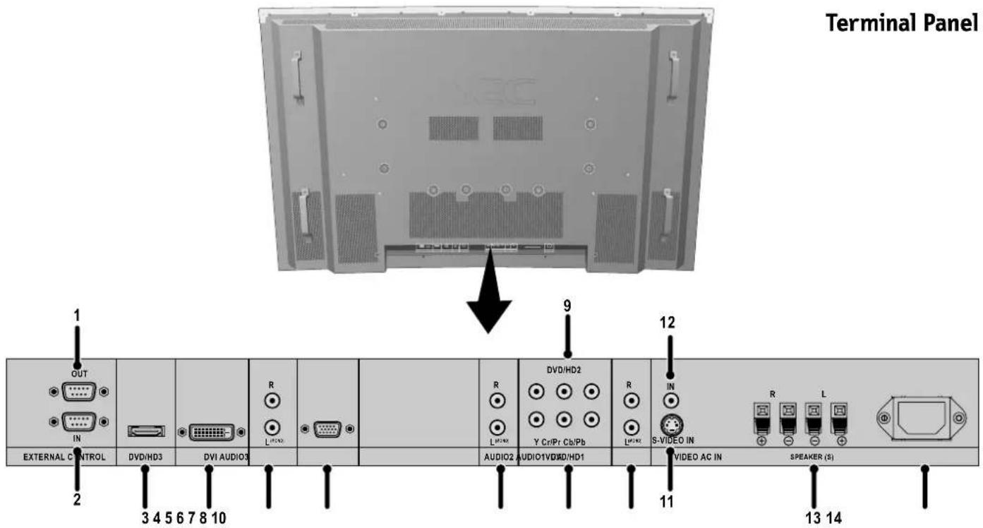
1) EXTERNAL CONTROL OUT (D-Sub 9 pin)
Connect RS-232C output to a second monitor.
2) EXTERNAL CONTROL (D-Sub 9 pin)
Connect RS-232C input to external equipment such as a PC in order to control RS-232C functions.
3) DVD/HD3 (HDMI)
Input digital HDMI signals.
4) DVI
Input digital RGB signals from a computer or HDTV device having a digital RGB output.
5) AUDIO3
Input the audio signal from external equipment such as a computer, VCR or DVD player.
6) VGA (Mini D-Sub 15 pin)
Analog computer input.
7) AUDIO2
Input the audio signal from external equipment such as a computer, VCR or DVD player.
8) DVD/HD1
Connect equipment such as a DVD player, HDTV device, or set-top box.
9) DVD/HD2
Connect equipment such as a DVD player, HDTV device or set-top.
10) AUDIO1
Input the audio signal from external equipment such as a computer, VCR or DVD player.
11) S-VIDEO in
Input S-video.
12)VIDEO1
Composite video input.
13) EXTERNAL SPEAKER (L and R) connector
Connects to optional speakers. Output the audio signal from AUDIO 1,2,and 3 to external speakers. NOTE:Speaker Terminal is for 8W + 8W (8 ohm).
14) AC IN
Connects with the supplied power cord.
Information:
For SCART connections there are 2 ways to connect:
SCART1: Connect R/G/B to the DVD/HD1 terminals and composite sync. to the VIDEO1 terminal.
SCART2: Connect R/G/B + composite sync. to the VGA terminal.
Remote Control Functions
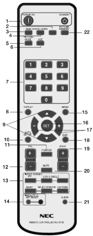
1) POWER ON/STANDBY
Switches the power on/standby.
*If the Power Indicator on the display is not glowing, then no controls will work.
2)VIDEO
Switches the input signal to the VIDEO source.
3) RGB
Switches the input signal to the RGB source.
4) DVD/HD
Switches the input signal to the DVD/HD source.
5) PICTURE MODE
Selects Picture Mode: [STANDARD], [BRIGHT], [CINEMA1], [CINEMA2], [DEFAULT].
STANDARD: for viewing in a bright room
BRIGHT: brighter picture than STANDARD
CINEMA1, 2: for viewing in a dark room, good for movies
DEFAULT: factory default settings
6) SIZE
Set the aspect ratio of the image.
7) KEYPAD
Set REMOTE ID.
8) DISPLAY
Turn on/off the Information OSD.
9) ▲▼
Move selection up or down
10) AUTO SETUP
Adjusts the CLOCK PHASE, CLOCK, and POSITION settings automatically. (Analog RGB signal input only)
11)POINTER
Turn on/off the pointer.
12)VOLUME
Increases/Decreases sound level.
13)SPLITSCREEN
PIP: Picture-in-Picture mode.
S BY S: Side-by-side mode.
SINGLE: Returns to normal mode.
SWAP: Swaps the Split Screen images.
SELECT/FREEZE: Selects which input is active when in split screen mode.
When the PICTURE FREEZE function (see OSD FUNCTION) is operating, SELECT/FREEZE can be used to display still pictures on the sub screen.
CAPTURE:Captures still picture.
14)REMOTEID
Activates REMOTE ID function.
15)MENU
Turns ON/OFF menu mode.
16)SET
Makes selection.
17)-,+
Increases or decreases amount of adjustment.
18)EXIT
Goes to the previous menu.
19)ZOOM
Enlarges or reduces the picture.
20)MUTE
Mutes audio output.
21)SLEEP
Sleep timer.
22)PICTUREMEMORY
Switches memory settings from 1 to 6.
POWER
To turn the unit ON and OFF:
- Plug the power cord into an AC outlet.
- Press the Power button (on the unit).
The monitor's ON/STANDBY indicator turns red and the unit will be in STANDBY mode.
- Press the POWER ON button on the remote control. The ON/STANDBY indicator will turn green when the unit is active.
- Press the STANDBY button (on the remote) or the Power button (on the unit) to turn off the monitor.
DISPLAY
To check display settings press the DISPLAY button on the remote. The screen changes each time the DISPLAY button is pressed. Display information will disappear after 3 seconds.
DIGITAL ZOOM
Digital zoom can change the picture position or enlarge the image on the screen.
- Be sure ZOOM NAV function is off. Press the ZOOM button (+ or -) to display the magnifying glass.
Press the ZOOM + button to enlarge the image.
Press the ZOOM - button to reduce the image.
Press the UP and DOWN or PLUS and MINUS buttons to reposition the picture. - Press the POINTER button to hide the pointer.
POINTER
Use the Pointer to point to a specific area on the screen.
Press the UP and DOWN or PLUS and MINUS buttons to reposition the Pointer.
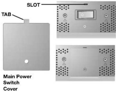
Main Power Switch Cover
Included with the display is a cover for the Main Power Switch. Use this cover to prevent the unit from being inadvertently powered off.
Place the tab on the cable cover into the rectangular slot on the display.
Th en using the screw provided, secure the cover to the display.
Remote Control ID Function
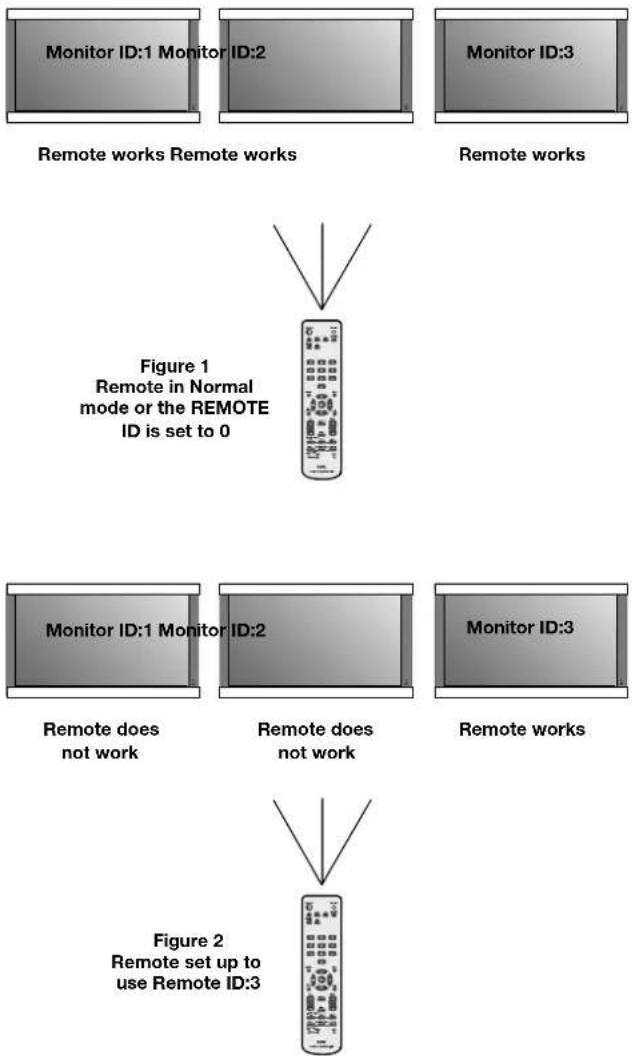
REMOTE CONTROL ID
The remote control included with the display can be used to control up to 26 individual monitors using what is called the REMOTE CONTROL ID mode. The REMOTE CONTROL ID mode works in conjunction with the Monitor ID, allowing control of up to 26 individual monitors. For example: if there are many monitors being used in the same area, a remote control in normal mode would send signals to every monitor at the same time Figure 1. Using the remote in REMOTE CONTROL ID mode will only operate one specific monitor within the group Figure 2.
TO SET REMOTE CONTROL ID:
While holding down the REMOTE ID SET button on the remote control, use the KEYPAD to input the Monitor ID (1-26) of the display to be controlled via remote. The remote can then be used to operate the monitor having that specific Monitor ID number.
When 0 is selected or when the remote control is in normal mode, all monitors will be operated.
TO USE REMOTE CONTROL ID MODE
ID Mode - To enter ID Mode press the REMOTE ID SET button and hold down for 2 seconds.
Normal Mode - To return to Normal Mode press the REMOTE ID RESET button and hold down for 2 seconds.
In order for this feature to work properly, the display must be assigned a Monitor ID number. The Monitor ID number can be assigned under the SETUP menu in the OSD (See page 17).
If Monitor ID is set to "ALL", monitor is controlled by remote control not depend on remote ID.
On-Screen Display (OSD)
Using the OSD
Use the Remote Control or the control panel on the front of the unit to enter the on-screen display menu to adjust settings.
- Press the MENU button on the remote or the EXIT button on the Control Panel.
- Use the up and down buttons to select the desired menu.
-
Press the SET button to select a sub-menu or item for adjustment.
-
Change the setting or adjustment by pressing the + and - buttons on the Control Panel or the Remote Control.
- Press the EXIT button on the Remote Control, on the Control Panel to return to the previous menu.
NOTE: Not all menu functions may be available. To access all functions the Advanced OSD option must be turned on in the ADVANCED OSD menu.
OSD Screen
ADVANCED OSD is OFF. Not all OSD functions will be available when the ADVANCED OSD is off.
Advanced OSD is ON. All OSD functions are shown, but some OSD functions may not be available.
On-Screen Display (OSD)
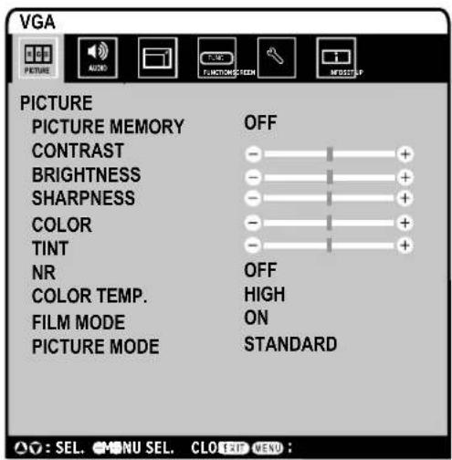
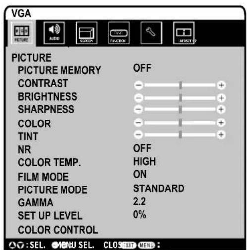
| Main Menu Sub | Menu Sub Menu2 | Explanation Default | Reset | ||
| PICTURE PICTURE | RE MEMORY Store picture menu settings | and input terminal information. The memory number is 1-6.The "PICTURE MEMORY" screen appears when the SET button is pressed on the "PICTURE MEMORY" MENU. | OFF YES | ||
| CONTRAST Adjusts the image brightness in relationship to the white level.Press + or - to adjust. | 50 YES | ||||
| BRIGHTNESS Adjusts the image brightness in relationship to the background.Press + or - to adjust. | 50 YES | ||||
| SHARPNESS Adjusts the crispness of the image. Press + or - to adjust. 50 YES | |||||
| COLOR | Adjusts the color depth of the screen. Press + or - to adjust. | 50 | YES | ||
| TINT | Adjusts the tint of the screen. Press + or - to adjust. | 50 | YES | ||
| NR | Adjusts the amount of noise reduction. Press + or - to adjust. | OFF | YES | ||
| COLOR TEMP. | Adjusts the color temperature of the entire screen. A low color temperature will make the screen reddish. A high color temperature will make the screen bluish. | MIDDLE | YES | ||
| WHITE BALANCE. | GAIN RED | The "WHITE BALANCE" appears when the SET button is pressed on the "COLOR TEMP." OSD menu.GAIN RED/GREEN/BLUE: Adjusts the white level of the white balance. | 50 YES | ||
| GAIN GREEN | 50 YES | ||||
| GAIN BLUE | 50 YES | ||||
| RESET | Resets the factory default settings. Select "ON", then press the SET button to reset. | OFF YES | |||
| FILM MODE | Selects Film mode. | ON | YES | ||
| PICTURE MODE | Selects picture mode, [BRIGHT], [STANDARD], [CINEMA1], [CINEMA2], [DEFAULT].STANDARD: For watching in a bright room.CINEMA1, 2: For watching in a dark room, especially good for movies.BRIGHT: Brighter picture than STANDARD.DEFAULT: Restores factory default settings. | STANDARD | YES | ||
| GAMMA Available only when the Advanced OSD function in the FUNCTION menu is enabled. | Select a display gamma for best picture quality.2.1, 2.2, 2.3, 2.4: The picture becomes darker as the number increases.S: Special gamma for certain types of movies. Raises the dark parts and lowers the light parts of the image. (S-Curve)These values are approximate. | 2.2 | YES | ||
| SET UP LEVEL Available only when the Advanced OSD function in the FUNCTION menu is enabled. | Adjusts the video black level.VIDEO signal input only. | 0% | YES | ||
| COLOR CONTROL Available only when the Advanced OSD function in the FUNCTION menu is enabled. | RED | Adjusts the levels of the Red, Green, Blue, Yellow, Magenta and Cyan.VIDEO and DVD/HD 1/2 input only. | 50 YES | ||
| GREEN | 50 YES | ||||
| BLUE | 50 YES | ||||
| YELLOW | 50 YES | ||||
| MAGENTA | 50 YES | ||||
| CYAN | 50 YES | ||||
| RESET | Resets the factory default settings. Select "ON", then press the SET button to reset. | OFF YES | |||
On-Screen Display (OSD)
| Main Menu Sub | Menu Sub Menu2 Explanation Default Reset | ||||
| AUDIO BASS Ad | usts the low frequency sound. Press + or - to adjust. 0 YES | ||||
| TREBLE Adjusts the high frequency sound. Press + or - to adjust. 0 YES | |||||
| BALANCE Adjusts the balance of L/R volume. Press + or - to adjust. 0 YES | |||||
| AUDIO INPUT1 | Select which audio input to use with the video source. | VIDEO1 | YES | ||
| AUDIO INPUT2 | DVD/HD1 | YES | |||
| AUDIO INPUT3 | VGA | YES | |||
| DVD/HD3 INPUT | HDMI | YES | |||
| SCREEN | ASPECT MODE | Selects aspect ratio of the displayed image. Press + or - to select. | - | - | |
| V-POSITION | Controls the vertical position of the image within the Display area of the PDP. Press + to move up. Press - to move down. | 0 | YES | ||
| H-POSITION | Controls the horizontal position of the image within the Display area of the PDP. Press + to move right. Press - to move left. | 0 | YES | ||
| V-HEIGHT Adjusts the vertical size of the image. 0 YES | |||||
| H-WIDTH | Adjusts the horizontal size of the image. | 0 YES | |||
| AUTO PICTURE | ON: H-Position, V-Position, Clock and Clock Phase are adjusted automatically. OFF: H-Position, V-Position, Clock and Clock Phase are adjusted manually. VGA input only. | OFF | NO | ||
| CLOCK PHASE | Adjusts the visual "noise" on the image. VGA input only. | 0 | YES | ||
| CLOCK | Press + to expand the width of the image on the right of the screen. Press - to narrow the width of the image on the left. VGA input only. | 0 | YES | ||
| UNDER SCAN Available only when the Advanced OSD function in the FUNCTION menu is enabled. | ON: UNDERSCAN is selectable in the ASPECT MODE menu. OFF: UNDERSCAN item is not selectable in the ASPECT MODE menu. Video signal input only. | OFF YES | |||
| SET UP Some functions available only when the Advanced OSD function in the FUNCTION menu is enabled. | LANGUAGE | Select the language used by the OSD. | ENGLISH | NO | |
| DVD/HD1 INPUT | Selects whether to set the input of the DVD/HD1 connector. COMPONENT : for Component input. (3BNC connectors) SCART1 : for SCART input (3RCA connectors and VIDEO1 input) (SCART1 available for Europe and World-Wide models only) | COMPONENT | YES | ||
| D-SUB INPUT | Selects whether to set the input of the mini D-SUB connector. RGB : for RGB input SCART2 : for SCART input (SCART2 available for Europe and World-Wide models only) | RGB | YES | ||
| HD SELECT | Selects signal detection for similar 1080I signal manually. 1080I : Standard digital broadcasts 540P : Special digital broadcasts (ex. DTC100) | 1080I | NO | ||
| RGB SELECT | If there is a problem with signal detection, this function forces the monitor to display the signal at the desired resolution. If no problem is detected, the only available option will be "AUTO". VGA input only. | AUTO | YES | ||
| HDMI MODE | Choose the HDMI mode based on the input device connected via HDMI connector. When a DVD player or similar equipment is connected, sets to "HIGH". When a PC or similar equipment is connected, sets to "LOW". | HIGH NO | |||
| DVI MODE | PLUG/PLAY | Choose the DVI mode based on the input device connected via DVI connector and set the black level. When a PC or similar equipment is connected, PLUG/PLAY is "DVI-PC" and BLACK LEVEL is "LOW". When a DVD player or similar equipment is connected, PLUG/PLAY is "DVI-HD" and BLACK LEVEL is "HIGH". | DVI-PC | NO | |
| BLACK LEVEL | LOW | NO | |||
| COLOR SYSTEM | The selected Color System depends on the video format of the input signal. VIDEO input only. | AUTO | NO | ||
On-Screen Display (OSD)
| Main Menu Sub | Menu Sub Menu2 Expl | lanation Default Reset | |||
| SET UP(continued) | BACK GROUND Choosess the brightness of background when there is no input signal present. | GRAY YES | |||
| SIDE MASK Adjusts the color of the side mask when a 4:3 image is displayed. Press + button, the bar will become lighter. Press - button, the bar will become darker. | 3 | YES | |||
| OSD DISPLAY OSD ON: Information about outputs, screen size, etc. is shown. OFF: No information is shown. | ON | YES | |||
| TOP LEFT | YES | ||||
| ON: The menu position intermittently shifts eight dots while the OSD is being displayed. OFF: The menu position does not shift. | |||||
| 70% YES | |||||
| MONITOR ID | Sets the monitor ID number from 1-26 or to "ALL". | ALL | YES | ||
| ALL RESET | Reset settings back to factory default values. | OFF | - | ||
| FUNCTIONSome functions available only when the Advanced OSD function in the FUNCTION menu is enabled.The ADVANCED OSD function is always available. | ADVANCED OSD | ON: All menu items are shown for advanced users. OFF: Some of the advanced menu items are not shown. | OFF YES | ||
| POWER SAVE | Sets how long the monitor waits to go into power save mode after a signal is lost. VGA and DVI input and Separate HV sync. only. | OFF YES | |||
| INPUT SKIP | Skipping next input if present input is no signal. This function is valid only for INPUT key on the display. | OFF YES | |||
| SUB PICTURE | SUB P.Detect | This function automatically detects no input signal of sub screen. This feature is available only picture-in-picture mode. SUB P.Detect: Sets availability of automatic detecting of sub screen. DISPLAY: Sets the appearance method of the sub screen. SUB P.RATE: Sets the transparency of the sub screen. | AUTO | YES | |
| DISPLAY | NORMAL | YES | |||
| SUB P.RATE | 100% | YES | |||
| ZOOM NAV | Sets the position of the zoom navigation image. | BTM LFT | YES | ||
| PICTURE FREEZE | Sets the position of the captured still picture. | S BY S1 | YES | ||
| SCREEN SAVER | Use the SCREEN SAVER function to reduce the risk of Image Persistence. PEAK BRIGHT : The brightness is decreased depending on setting. ORBITER : The screen image moves slightly with squeezing or expanding. INVERSE : The screen image is displayed alternately between positive image and negative image, or the screen image is displayed full white. | MANUAL | YES | ||
| PEAK BRIGHT | 100% | YES | |||
| ORBITER | AUTO1 | YES | |||
| INVERSE/WHITE | OFF YES | ||||
| CLOSED CAPTION (U.S. models only) | Chooses the closed caption setting. | OFF | YES | ||
| CAPTION CONT (U.S. models only) | Chooses the brightness of the closed caption. | NORMAL | YES | ||
| INPUT DETECT | INPUT | Sets the input mode and the sound volume when the power turn on. LAST : last mode (the input that was last selected when the power turn off.) MULTI to DVI : fixed input mode. AUTO : Searches the input with the signal automatically PRIORITY : Sets the priority input for AUTO setting. | LAST | YES | |
| VOLUME | LAST | YES | |||
| PROTOCOL SET | Sets protocol setting of RS-232C. OFF : When NEC protocol is used (normal). ON : When special protocol is used. * Consult your dealer for details of protocol. | OFF | YES | ||
| RS232C CONTROL | Selects the mode of the monitor when using the RS-232C daisy chain. | NORMAL | YES | ||
| SIGNAL INFORMATION | Display signal information such as frequencies, polarities, etc. | - | - | ||
No picture
- The signal cable should be properly connected to the display card/computer.
- The display card should be properly seated in its slot.
- Front Power Switch and computer power switch should be in the ON position.
- Check to make sure that a supported mode has been selected on the display card or system being used. (Please consult display card or system manual to change graphics mode.)
- Check the monitor and your display card with respect to compatibility and recommended settings.
- Check the signal cable connector for bent or pushed-in pins.
Power Button does not respond
- Unplug the power cord of the monitor from the AC outlet to turn off and reset the monitor.
Image persistence
- Please be aware that Plasma Technology may experience a phenomena known as Image Persistence. Image Persistence occurs when a residual or "ghost" image of a previous image remains visible on the screen. Unlike CRT monitors, Plasma monitors' image persistence is not permanent, but constant images being displayed for a long period of time should be avoided. To alleviate image persistence, turn off the monitor for as long as the previous image was displayed. For example, if an image was on the monitor for one hour and a residual image remains, the monitor should be turned off for one hour to erase the image.
NOTE: As with all personal display devices, NEC DISPLAY SOLUTIONS recommends displaying moving images and using a moving screen saver at regular intervals whenever the screen is idle or turning off the monitor when not in use.
Image is unstable, unfocused or
swimming is apparent
- Signal cable should be properly attached to the Plasma monitor, computer, or other input device.
- Use the OSD screen controls to focus and adjust display by increasing or decreasing the clock phase total. When the display mode is changed, the OSD Image Adjust settings may need to be readjusted.
- Check the monitor and your display card with respect to compatibility and recommended signal timings.
Image of component signal is greenish
- Check to see if the DVD/HD input connector is selected.
LED on monitor is not lit
(no green or red color can be seen)
- Main Power Switch should be in the ON position and power cord should be connected.
Red LED on monitor is blinking
- A certain failure might have occurred, please contact your nearest authorized NEC DISPLAY SOLUTIONS service facility.
Display image is not sized properly
- Use the OSD screen controls to increase or decrease the clock total.
- Check to make sure that a supported mode has been selected on the display card or system being used. (Please consult display card or system manual to change graphics mode.)
Selected resolution is not displayed properly
- Use OSD information to enter Information menu and confirm that the appropriate resolution has been selected. If not, select appropriate resolution.
No Sound
- Check to see if speaker cable is properly connected.
- Check to see if mute is activated.
- Check to see if volume is set at minimum. NOTE: It is possible to play audio from a source that is different from the video source.
RS-232C does not work
- Check the PROTOCOL SET in the FUNCTION menu.
Remote Control does not work
- Make sure the batteries are inserted properly.
Test the batteries for strength/life. - Make sure to point the remote directly at the sensor on the monitor.
- Check if the remote is in Remote ID mode.
- The remote control may not function when in direct sunlight or when there is strong illumination on the remote sensor of the monitor.
Specifications 42XC10
| PDP Module Diagonal: 42°/1058 mm | ||||
| Pixel Pitch 0.900 mm (W)/0.676 mm (II) | ||||
| Resolution 1024 x 768 | ||||
| Frequency Horizontal ANALOG: 15.625/15.734Hz 1Hz, 31.0k1Hz - 108.5k1Hz | ||||
| DIGITAL: 15.625/15.734kHz, 31.0kHz - 91.1kHz | ||||
| Vertical 24Hz to 120.4Hz | ||||
| Panel Display Size 922 mm (W) x 519 mm (II)36.3 in (W) x 20.4 in (II) | ||||
| Input Signals DVI DVI-D 24pin Digital RGB DV1 (HDCP) | ||||
| VGA60, SVGA60, XGA60, WXGA60, SXGA60, UXGA60*, 1920X1080* | ||||
| VGA 15pin Mini D-sub Analog RGB | 0.7V p-p, Input Impedance 75 ohm | |||
| VGA60, SVGA60, XGA60, WXGA60, SXGA60, UXGA60* | ||||
| Sync Separate: TT L level (Pos./Neg.) | ||||
| Composite sync on Green Video: 0.3Vp-p Neg | ||||
| DVD/HID1.2 RCA (Y, Cb/Pb, Cr/Pr) | Component | Y: 1.0Vp-p/75ohm, Cb/Cr (Pb/Pr): 0.7Vp-p/75 ohm | ||
| HDTV/DVD:1080p*, 1080i*, 720p@50Hz/60Hz,576p@50Hz, 480p@60Hz, 576i@50Hz, 480i@60Hz | ||||
| DVD/HD3 (HDMI) | HDMI Type-A Digital | Component | HDMI | |
| 1080p*,1080i*,720p@50Hz/60Hz, 576p@50Hz, 480p@60Hz, 576i@50Hz, 480i@60Hz | ||||
| VIDEO1 | RCA | Composite | 1.0V p-p Input Impedance 75 ohm | |
| NTSC/PAI(B, G, M, N)/SECAM/4.43NTSC/PAI.60 | ||||
| S-VIDEO | mini DIN 4 pin | S-VIDEO | Y: 1.0Vp-p/75ohm C: 0.286Vp-p/75 ohm(NTSC),0.3Vp-p/75ohm(PAL/SECAM) | |
| NTSC/PAI(B, G, M, N)/SECAM/4.43NTSC/PAI.60 | ||||
| Audio | AUDIO Input | RCA (L/R) X3 | Analog Audio | Stereo L/R 0.5Vrms |
| HDMI Type-A DIGITAL Audio PCM 32, 4A1, 48Khz (16bit) | ||||
| Speaker Output | External Speaker Jack 8W + 8W (8 ohm) | |||
| External Control | RS-232C: IN | 9 Pin D-sub | ||
| RS-232C: OUT | 9 Pin D-sub (daisy chain) | |||
| Power Supply | 4.4-1.8A@100-240V AC, 50/60Hz | |||
| Operational Environment | Temperature | 0° to 40°C / 32°F to 104°F | ||
| Humidity | 20% to 80% (without condensation) | |||
| Storage Environment | Temperature | -10°C to 50°C / 14°F to 122°F | ||
| Humidity | 10 - 90% (without condensation) / 90% - 2% x (Temp - 40°C) regarding over 40°C | |||
| Dimensions (W×L×D) | Net | 1036mm(W) x 649mm(11) x 130mm(D) / 40.8"(W) x 25.6"(11) x 5.1"(D) | ||
| Gross | 1220mm(W) x 900mm(H) x 360mm(D) / 48.0"(W) x 35.4"(H) x 14.2"(D) | |||
| Weight(without speaker and stand) | Net | 34.5 kg / 76.1 lbs | ||
| Gross | 42.5 kg / 93.7 lbs | |||
| VESA compatible armmounting interface | 700mm x 300mm4 Holes (screw M8 Depth 16mm) | |||
| Complied Regulatoryand Guidelines | UL 60065/CSA C22.2 No.60065/EN60065/IEC60065FCC: B/DOC-B/EN55022 B/EN55024/EN61000-3-2/EN61000-3-3/CE/C-Tick | |||
| Power Management | VESA DPM (Separate IIV Sync. only) | |||
| Plug & Play | VESA DDC2B | |||
| Accessories | Remote control, AA Batteries, Power cord, Users Manual (CD-ROM),Start Up Guide (Paper / CD-ROM), Main Power Switch cover and screw, Cable clamps | |||
| *Compressed Image | ||||
Specifications 50XC10
| PDP Module Diagonal: 50"1 | 269 mm | |||
| Pixel Pitch 0.81 mm (W)/0.81 mm (II) | ||||
| Resolution 1365 x 768 | ||||
| Frequency 1 Horizontal ANALOG: 15.625/15.734Hz | DIGITAL: 15.625/15.734kHz, 31.0kHz - 91.1kHz | |||
| Vertical 24Hz to 120.4Hz | ||||
| Panel Display Size 1106 mm(W) x 622 mm (II)43.5 in (W) x 24.5 in (II) | ||||
| Input Signals DVI DVI-D 24pin Digital RGB DVI | I (HDCP) | |||
| VGA60, SVGA60, XGA60, WXGA60, SXGA60, UXGA60*, 1920X1080* | ||||
| VGA 15pin Mini D-sub Analog RGB | 0.7V p-p, Input Impedance 75 ohm | |||
| VGA60, SVGA60, XGA60, WXGA60, SXGA60, UXGA60* | ||||
| Sync Separate: TT L level (Pos./Neg.) | ||||
| Composite sync on Green Video: 0.3Vp-p Neg | ||||
| DVD/HID1.2 | RCA (Y, Cb/Pb, Cr/Pr) | Component | Y: 1.0Vp-p/75ohm, Cb/Cr (Pb/Pr): 0.7Vp-p/75 ohm | |
| HDTV/DVD:1080p*, 1080i*, 720p@50Hz/60Hz,576p@501Hz, 480p@601Hz, 576i@501Hz, 480i@601Hz | ||||
| DVD/HD3(HDMI) | HDMI Type-A Digital | Component | HDMI | |
| 1080p*,1080i*,720p@50Hz/601Hz, 576p@50Hz, 480p@601Hz, 576i@501Hz, 480i@60Hz | ||||
| VIDEO1 | RCA | Composite | 1.0V p-p Input Impedance 75 ohm | |
| NTSC/PAI(B, G, M, N)/SECAM/4.43NTSC/PAI60 | ||||
| S-VIDEO | mini DIN 4 pin | S-VIDEO | Y: 1.0Vp-p/75ohm C: 0.286Vp-p/75 ohm(NTSC),0.3Vp-p/75ohm(PAL/SECAM) | |
| NTSC/PAI(B, G, M, N)/SECAM/4.43NTSC/PAI60 | ||||
| Audio | AUDIO Input | RCA (L/R) X3 | Analog Audio | Stereo L/R 0.5Vrms |
| HDMI Type-A DIGITAL | Audio PCM 32, 41.1, 48Khz (16bit) | |||
| Speaker Output | External Speaker Jack 8W + 8W (8 ohm) | |||
| External Control | RS-232C: IN | 9 Pin D-sub | ||
| RS-232C: OUT | 9 Pin D-sub (daisy chain) | |||
| Power Supply | 6.0-2.6A@100-240V AC, 50/601Hz | |||
| Operational Environment | Temperature | 0° to 40°C / 32°F to 104°F | ||
| Humidity | 20% to 80% (without condensation) | |||
| Storage Environment | Temperature | -10°C to 50°C / 14°F to 122°F | ||
| Humidity | 10 - 90% (without condensation) / 90% - 2% x (Temp - 40°C) regarding over 40°C | |||
| Dimensions (Wx1IxD) | Net | 1221mm(W) x 748mm(I1) x 130mm(D) / 48.1"(W) x 29.4"(I1) x 5.1"(D) | ||
| Gross | 1400mm(W) x 980mm(H) x 360mm(D) / 55.1"(W) x 38.6"(H) x 14.2"(D) | |||
| Weight(without speaker and stand) | Net | 49.0 kg / 108.0 lbs | ||
| Gross | 59.0 kg / 130.1 lbs | |||
| VESA compatible armmounting interface | 700mm x 300mm4 Holes (screw M8 Depth 16mm) | |||
| Complied Regulatoryand Guidelines | UL 60065/CSA C22.2 No.60065/EN60065/IEC60065FCC-B/DOC-B/EN55022 B/EN55024/EN61000-3-2/EN61000-3-3/CE/C-Tick | |||
| Power Management | VESA DPM (Separate 11V Sync. only) | |||
| Plug & Play | VESA DDC2B | |||
| Accessories | Remote control, AA Batteries, Power cord, Usrs Manual (CD-ROM),Start Up Guide (Paper / CD-ROM), Main Power Switch cover and screw, Cable clamps | |||
| *Compressed Image | ||||
Specifications 60XC10
| PDP Module Diagonal: 60°/154 mm | ||||
| Pixel Pitch 0.966 mm (W)/0.966 mm (II) | ||||
| Resolution 1366 x 768 | ||||
| Frequency Horizontal ANALOG: 15.625/15.734Hz 1Hz, 31.0k1Hz - 108.5k1Hz | ||||
| DIGITAL: 15.625/15.734kHz, 31.0kHz - 91.1kHz | ||||
| Vertical 24Hz to 120.4Hz | ||||
| Panel Display Size 1320 mm (W) x 742 mm (II)51.9 in (W) x 29.2 in (II) | ||||
| Input Signals DVI DVI-D 24pin Digital RGB DVII(HDCP) | ||||
| VGA60, SVGA60, XGA60, WXGA60, SXGA60, UXGA60*, 1920X1080* | ||||
| VGA60, SVGA60, XGA60, WXGA60, SXGA60, UXGA60* | ||||
| Sync Separate: TT | L level (Pos./Neg.) | |||
| Composite sync on Green Video: 0.3Vp-p Neg | ||||
| DVD/HID1.2 | RCA (Y, Cb/Pb, Cr/Pr) | Component | Y: 1.0Vp-p/75ohm, Cb/Cr (Pb/Pr): 0.7Vp-p/75 ohm | |
| HDTV/DVD:1080p*, 1080i*, 720p@50Hz/60Hz,576p@50Hz, 480p@60Hz, 576i@50Hz, 480i@60Hz | ||||
| DVD/HD3 (HDMI) | HDMI Type-A Digital | Component | HDMI | |
| 1080p*,1080i*,720p@50Hz/60Hz,576p@50Hz, 480p@60Hz, 576i@50Hz, 480i@60Hz | ||||
| VIDEO1 | RCA | Composite | 1.0V p-p Input Impedance 75 ohm | |
| NTSC/PAI(B, G, M, N)/SECAM/4.43NTSC/PAI.60 | ||||
| S-VIDEO | DIN 4 pin | S-VIDEO | Y: 1.0Vp-p/75ohm C: 0.286Vp-p/75 ohm(NTSC),0.3Vp-p/75ohm(PAI/SECAM) | |
| NTSC/PAI(B, G, M, N)/SECAM/4.43NTSC/PAI.60 | ||||
| Audio | AUDIO Input | RCA (L/R) X3 | Analog Audio | Stereo L/R 0.5Vrms |
| HDMI Type-A DIGITAL | Audio PCM 32, 44.1, 48Khz (16bit) | |||
| Speaker Output | External Speaker Jack 8W + 8W (8 ohm) | |||
| External Control | RS-232C: IN | 9 Pin D-sub | ||
| RS-232C: OUT | 9 Pin D-sub (daisy chain) | |||
| Power Supply | 7.8-3.2A@100-240V AC, 50/60Hz | |||
| Operational Environment | Temperature | 0' to 40°C / 32" F to 104" F | ||
| Humidity | 20% to 80% (without condensation) | |||
| Storage Environment | Temperature | -10°C to 50°C / 14" F to 122" F | ||
| Humidity | 10 - 90% (without condensation)/ 90% - 2% x (Temp - 40°C) regarding over 40°C | |||
| Dimensions (Wx11xD) | Net | 1447mm(W) x 876mm(11) x 130mm(D) / 57.0"(W) x 34.5"(11) x 5.1"(D) | ||
| Gross | 1620mm(W) x 1100mm(H) x 360mm(D) / 63.8"(W) x 43.3"(H) x 14.2"(D) | |||
| Weight(without speaker and stand) | Net | 70.0 kg / 154.3 lbs | ||
| Gross | 83.0 kg / 183.0 lbs | |||
| VESA compatible armmounting interface | 700mm x 300mm4 Holes (screw M8 Depth 16mm) | |||
| Complied Regulatoryand Guidelines | UL 60065/CSA C22.2 No.60065/EN60065/IEC60065FCC-B/DOC-B/EN55022 B/EN55024/EN61000-3-2/EN61000-3-3/CE/C-Tick | |||
| Power Management | VESA DPM (Separate IIV Sync. only) | |||
| Plug & Play | VESA DDC2B | |||
| Accessories | Remote control, AA Batteries, Power cord, Users Manual (CD-ROM),Start Up Guide (Paper / CD-ROM), Main Power Switch cover and screw, Cable clamps | |||
| *Compressed Image | ||||
42XC10 Supported Resolutions (PC)
| Slg.no. | H X V | Specification of the signal | Input terminal | ANalog | Digital | Output terminal | SZE | Sync polari | t Sync presence | B&Effct | |||||||||||||
| Rampitude(Hz) | H freq.(kHz) | NORMAL(4:3) | FULL(16:9) | ZOOM | NORMAL(4:3) | FULL(16:9) | ZOOM | H | V | ||||||||||||||
| IBM PC/ATCompatible Computers | 1 | 640 X 400 | 400line | 70.1 | 31.5 | VGA | -- | Yes | -- | DVI(DVI-PC) | -- | -- | -- | Neg. | Neg. | Yes | 1 | 640X400 | |||||
| 2 | 720 X 400 | 400line | 70.1 | 31.5 | -- | Yes | -- | -- | Yes | -- | Neg. | Neg. | Yes | 1 | 720X400 | ||||||||
| 3 | 85 | 37.9 | -- | Yes | -- | -- | Yes | -- | Neg. | Pos. | Yes | -- | -- | ||||||||||
| 4 | 720 X 350 | 350line | 70.1 | 31.5 | -- | Yes | -- | -- | Yes | -- | neg. | Neg. | Yes | 1 | 720X350 | ||||||||
| 5 | 640 X 480 | VGA | 58.9 | 31.5 | Yes | Yes | Yes | Yes | Yes | Yes | Neg. | Neg. | Yes | 2 | 640X480 | ||||||||
| 6 | 72.8 | 37.9 | Yes | Yes | Yes | Yes | Yes | Yes | Neg. | Neg. | Yes | -- | -- | ||||||||||
| 7 | 75 | 37.5 | Yes | Yes | Yes | Yes | Yes | Y es | eN g. | eN g. | Yes | -- | -- | ||||||||||
| 8 | 85 | 43.3 | Yes | Yes | Yes | Yes | Yes | Yes | Neg. | Neg. | Yes | -- | -- | ||||||||||
| 9 | 100.4 | 51.1 | Yes | Yes | Yes | Yes | Yes | Yes | Neg. | Neg. | Ye s | -- | -- | ||||||||||
| 10 | 120.4 | 61.3 | Yes | Yes | Yes | Yes | Yes | Yes | Neg. | Neg. | Yes | -- | -- | ||||||||||
| 11 | 848 X 480 | Wide-VGA | 60 | 31 | -- | Yes | -- | -- | Yes | -- | oFp. | Pos. | Yes | 2 | 848X480 | ||||||||
| 12 | 852 X 480 | Wide-VGA | 60 | 31.7 | -- | Yes | -- | -- | Yes | -- | Neg. | Neg. | Yes | 2 | 852X480 | ||||||||
| 13 | 800 X 600 | SVGA | 56.3 | 35.2 | Yes | Yes | Yes | Yes | Yes | Yes | Pos. | Pos. | Yes | -- | -- | ||||||||
| 14 | 60.3 | 37.9 | Yes | Yes | Yes | Yes | Yes | Yes | Pos. | Pos. | Yes | -- | -- | ||||||||||
| 15 | 72.2 | 48.1 | Yes | Yes | Yes | Yes | Yes | Yes | Pos. | Pos. | Yes | -- | -- | ||||||||||
| 16 | 75 | 48.9 | Yes | Yes | Yes | Yes | Yes | Yes | Pos. | Pos. | sEy | -- | -- | ||||||||||
| 17 | 85.1 | 53.7 | Yes | Yes | Yes | Yes | Yes | Yes | Pos. | Pos. | Yes | -- | -- | ||||||||||
| 18 | 90.8 | 63 | Yes | Yes | Yes | Yes | Yes | Yes | Pos. | Pos. | Yes | -- | -- | ||||||||||
| 19 | 120.4 | 75.7 | Yes | Yes | Yes | Yes | Yes | Yes | Pos. | Pos. | Yes | -- | -- | ||||||||||
| 20 | 1024 X 768 | XGA | 60 | 48.4 | Yes | Yes | Yes | Yes | Yes | Yes | Neg. | Neg. | Yes | 3 | 1024X768 | ||||||||
| 21 | 70.1 | 56.5 | Yes | Yes | Yes | Yes | Yes | Yes | Neg. | Neg. | Yes | 5 | 1024X768 | ||||||||||
| 22 | 71.9 | 57.9 | Yes | Yes | Yes | Yes | Yes | Yes | Neg. | Neg. | Yes | 6 | 1024X768 | ||||||||||
| 23 | 75 | 60 | Yes | Yes | Yes | Yes | Yes | Yes | P os. | off. | Yes | -- | -- | ||||||||||
| 24 | 85 | 68.7 | Yes | Yes | Yes | Yes | Yes | Yes | Pos. | Pos. | Yes | -- | -- | ||||||||||
| 25 | 100.8 | 80.5 | Yes | Yes | Yes | Yes | Yes | Yes | edj. | Ne g. | edj. | -- | -- | ||||||||||
| 26 | 119.4 | 95.5 | Yes | Yes | Yes | Yes | csf. | cfj. | No g. | cfj. | -- | -- | |||||||||||
| 27 | 1152 X 864 | XGA | 60 | 53.7 | Yes | Yes | Yes | Yes | Yes | Yes | Pos. | No g. | cfj. | -- | -- | ||||||||
| 28 | 72 | 64.9 | Yes | Yes | Yes | Yes | Yes | Yes | Pos. | Neg. | Ye s | -- | -- | ||||||||||
| 29 | 75 | 67.5 | Yes | Yes | Yes | Yes | Yes | Yes | Pos. | Pos. | Ye s | -- | -- | ||||||||||
| 30 | 1280 X 768 | Wide-XGA | 56.2 | 45.1 | -- | csf. | -- | -- | -- | -- | Pos. | off. | Ye s | -- | -- | ||||||||
| 31 | 59.8 | 48 | -- | Yes | -- | -- | Yes | s | cfj. | Neg. | Neg. | Yes | 3 | 1280 X768-2 | |||||||||
| 32 | 59.9 | 47.8 | -- | Yes | -- | -- | Yes | -- | Neg. | cfj. | Pos. | 5 | 1280X768-2 | ||||||||||
| 33 | 69.8 | 65 | -- | Yes | -- | -- | Yes | -- | edj. | Pos. | Yes | 6 | 1280X768 | ||||||||||
| 34 | 72 | 57.8 | -- | Yes | -- | -- | Y es. | -- | Neg. | Pos. | Yes | 6 | 1280X768 | ||||||||||
| 35 | 1280 X 800 | Wide-XGA | 59.8 | 49.7 | -- | Yes | -- | -- | Y es. | -- | Neg. | cfj. | Yes | 4 | 12 890 | ||||||||
| 36 | 1280 X 854 | Wide-XGA | 60 | 53.1 | -- | Yes | -- | -- | Y es. | -- | Neg. | Neg. | cfj. | -- | -- | ||||||||
| 37 | 1280 X 960 | Wide-XGA | 60 | 60 | Yes | Yes | Yes | Y ass. | cfj. | Yes | Pos. | Pos. | sEy. | -- | -- | ||||||||
| 38 | 85 | 85.9 | Yes "2" | Ye | ef223 | Yes | Yes | Yes | Pos. | Pos. | sEy. | -- | -- | ||||||||||
| 39 | 1360 X 768 | Wide-XGA | 60 | 47.7 | -- | Yes | -- | -- | cfj. | -- | Pos. | Pos. | cfj. | 3 | 1380X768 | ||||||||
| 40 | 1376 X 768 | Wide-XGA | 59.9 | 48.3 | -- | Yes | -- | -- | Yes | -- | cfj. | cfj. | Yes | 3 | 1376X768 | ||||||||
| 41 | 1280 X 1024 | SXGA | 60 | 64 | Yes "1" | Yes | Yes | Yes "1" | Yes | Yes | Pos. | Pos. | Yes | 9 | 1280X1024 | ||||||||
| 42 | 75 | 80 | Yes "1" | cfj. | Yes | Yes "1" | Yes | Yes | cfj. | Pos. | Yes | -- | -- | ||||||||||
| 43 | 85 | 91.1 | Yes "1"2" | Yes "2" | Yes "2" | Yes "1"2" | Yes | Yes"2" | cfj. | cfj. | Yes | -- | -- | ||||||||||
| 44 | 100.1 | 108.5 | Yes "1"2" | Yes "2" | Yes "2" | -- | -- | -- | Pos. | Pos. | Yes | -- | -- | ||||||||||
| 45 | 1400 X 1050 | SXGA+ | 60 | 64 | Yes | Yes | Yes | Yes | Yes | Yes | Neg. | Pos. | Yes | 9 | 1400X1050 | ||||||||
| 46 | 60 | 653 | Yes | Yes | Yes | Yes | Yes | Yes | Neg. | Pos. | Yes | 7 | 1400X1050 | ||||||||||
| 47 | 74.9 | 82.3 | Yes "2" | Yes "2" | Yes "2" | Yes | Yes | Y orc. | cfj. | Pos. | Pos. | -- | -- | ||||||||||
| 48 | 85 | 93.9 | Yes "2" | Yes "2" | Yes "2" | -- | -- | -- | Neg. | Pos. | Yes | -- | -- | ||||||||||
| 49 | 1680 X 1050 | Wide-SXGA | 60 | 65.3 | -- | Yes | -- | -- | Yes | -- | Neg. | Pos. | Yes | 7 | 1680X1050 | ||||||||
| 50 | 60 | 75 | Yes "2" | Yes "2" | Yes | Yes | Yes | Pos. | Pos. | Yes | 8 | 1600X1200 | |||||||||||
| 51 | 65 | 81.3 | -- | Yes "2" | Yes "2" | -- | -- | -- | Pos. | Pos. | Yes | -- | -- | ||||||||||
| 52 | 70 | 87.5 | -- | 2" 2" 2" 2" | -- | -- | -- | Pos. | Pos. | Yes | -- | -- | |||||||||||
| 53 | 75 | 93.8 | -- | Y 2" 2" 2" 2" | -- | -- | -- | Pos. | Pos. | Yes | -- | -- | |||||||||||
| 54 | 85 | 106.3 | Yes "2" | Yes "2" | -- | -- | -- | Pos. | Pos. | Yes | -- | -- | |||||||||||
| 55 | 1920 X 1080 | 60 | 56.2 | -- | -- | -- | -- | cfj. | -- | Pos. | Pos. | Yes | -- | -- | |||||||||
| 56 | 60 | 67.5 | -- | -- | -- | -- | Yes | -- | Pos. | Pos. | Yes | -- | -- | ||||||||||
| 57 | 1920 X 1200 | Wide-UXGA | 59.9 | 74.6 | -- | Yes "2" | -- | -- | Yes "2" | -- | Neg. | Pos. | Yes | 8 | 1920X1200 | ||||||||
| 58 | 60 | 74 | -- | Yes "2" | -- | -- | Yes "2" | -- | Neg. | Pos. | Yes | -- | -- | ||||||||||
| 59 | 72 | 78.1 | Yes "1" | Yes "2" | -- | Yes "1" | Yes | Neg. | Neg. | Yes | -- | -- | |||||||||||
| 60 1152 X 624 1024 1024 X 768 11280 X 1024 11280 X 1024 11280 X 1024 11280 X 1024 11280 X 1024 11280 X 1024 11280 X 1024 11280 X 1024 11280 X 1024 11190 X 1024 11190 X 1024 11190 X 1024 11190 X 1024 11190 X 1024 11190 X 1024 11190 X 1024 11190 X 1024 11190 X 960 11280 X 1024 11280 X 1024 11280 X 1024 11280 X 1024 11280 X 1024 11280 X 1024 11280 X 1024 11280 X 1024 11300 X 1024 11300 X 1024 11300 X 1024 11300 X 1024 11300 X 1024 11300 X 1024 11300 X 1024 11300 X 1024 11300 X 960 11280 X 1024 11280 X 1024 11280 X 1024 11300 X 1024 11300 X 960 11280 X 1024 11300 X 960 11300 X 960 11300 X 960 11300 X 960 11300 X 960 11300 X 960 11300 X 960 11300 X 960 11300 X 960 11300 X 960 X 960 X 960 X 960 X 960 X 960 X 960 X 960 X 960 X 960 X 960 X 960 X 960 X 960 X 960 X 960 X 960 X 960 X 960 X 960 X 959 X 960 X 960 X 960 X 960 X 960 X 960 X 960 X 960 X 960 X 960 X 960 X 960 X 960 X 960 X 960 X 960 X 960 X 960 X 960 X 96 | |||||||||||||||||||||||
| - | NORMAL (4:3) | FULL(16:9) | ('1') | ('2') |
| Not Supported | 768 pixels x 768 lines | 1024 pixels x 768 lines | Aspect ratio is 5:4 (720x768) | Rough Sampling |
42XC10 Supported Resolutions (Video)
| Sig. no. | c Resolution H X V Signal Type | Specification of the signal | INPUT Initial (4:9) | SIZE | Digital | ||||||||||||||||
| V freq. (Hz) | H freq. (kHz) | NORMAL (16:9) | FULL | DYNAMIC (non-linear) | ZOOM | 14:9 | 235:1 | UNDER SCAN | INPUT terminal | SIZE | |||||||||||
| Video Composite / S | 101 | 3.58NTSC | 59.9 | 15.8 | Video1 S-Video | Yes | Yes | Yes | Yes | Yes | Yes | Yes 3 | -- | -- | -- | -- | -- | -- | -- | ||
| 102 | 4.43NTSC | 59.9 | 15.8 | Yes | Yes | Yes | Yes | Yes | Yes | Yes 3" | -- | -- | -- | -- | -- | -- | |||||
| 103 | PAL | 50 | 15.6 | Yes | Yes | of | Yes | Yes | Yes | Yes 3 | -- | -- | -- | -- | -- | -- | |||||
| 104 | PAL60 | 58.9 | 15.8 | Yes | Yes | Yes | Yes | Yes | Yes | Yes 3 | -- | -- | -- | -- | -- | -- | |||||
| 105 | PAL-N | 50 | 15.6 | Yes | Yes | Yes | Yes | Yes | Yes | Yes 3 | -- | -- | -- | -- | -- | -- | |||||
| 106 | PAL-M | 59.9 | 15.8 | Yes | Yes | Yes | Yes | Yes | Yes | Y es" | -- | -- | -- | -- | -- | -- | |||||
| 107 | SECAM | 50 | 15.6 | Yes | Yes | Yes | Yes | Yes | Yes | Yes 3" | -- | -- | -- | -- | -- | -- | |||||
| Y,Pb(Cb),Pr(Cr) | SD | 111 | 480I | 59.9 | 15.8 | DVD/HD1 DVD/HD2 | Yes | Yes | Yes | Yes | Yes | Yes | Yes 3" | -- | -- | -- | -- | -- | -- | -- | |
| 112 | 576I | 50 | 15.6 | Yes | Yes | Yes | Yes | Yes | Yes | Yes 3" | -- | -- | -- | -- | -- | -- | |||||
| 113 | 480P | 959 | 31.5 | Yes | Yes | Yes | Y se | Yes | Yes | Y es" | -- | -- | -- | -- | -- | -- | |||||
| 114 | 576P | 05 | 13.5 | Yes | Yes | Yes | Y se | Yes | Yes | Yes 3" | -- | -- | -- | -- | -- | -- | |||||
| HD | 115 | 720P | 05 | 75.5 | -- | Yes | Yes | -- | -- | Yes | Yes 3" | -- | -- | -- | -- | -- | -- | ||||
| 116 | 720P | 60 | 4.5 | -- | Yes | Yes | -- | -- | Yes | Yes 3" | -- | -- | -- | -- | -- | -- | |||||
| 117 | 1080I | 50 | 28.1 | -- | Yes | Yes | -- | -- | Yes | Yes 3" | -- | -- | -- | -- | -- | -- | |||||
| 118 | 1080I | 06 | 33.8 | -- | Yes | Yes | -- | -- | Yes | Yes 3" | -- | -- | -- | -- | -- | -- | |||||
| 119 | 1080P | 50 | 56.3 | -- | Yes | Y se | -- | -- | Yes | Yes 3" | -- | -- | -- | -- | -- | -- | |||||
| 120 | 1080P | 06 | 76.5 | -- | Yes | Yes | -- | -- | Yes | Yes 3" | -- | -- | -- | -- | -- | -- | |||||
| 121 | 1080P | 30 | 33.8 | -- | Yes | Yes | -- | -- | Yes | Yes 3" | -- | -- | -- | -- | -- | -- | |||||
| 122 | 1080P | 42 | 72 | -- | Yes | Yes | -- | -- | Yes | Yes 3 | -- | -- | -- | -- | -- | -- | |||||
| 123 | 1080P | 25 | 28 | -- | Yes | Yes | -- | -- | Yes | Yes 3 | -- | -- | -- | -- | -- | -- | |||||
| RGB(Video signal) | SD | 131 | 480I 4 | 59.9 | 15.8 | VGA (SCART1-2) | Yes | Yes | Yes | Yes | Yes | Yes 3" | -- | -- | -- | -- | -- | -- | -- | ||
| 132 | 576I 4 | 50 | 15.6 | Yes | Yes | Yes | Yes | Yes | Yes | Yes 3" | -- | -- | -- | -- | -- | -- | |||||
| 133 | 480P | 59.9 | 31.5 | Yes | Yes | Yes | Yes | Yes | Yes | Yes 3" | -- | -- | -- | -- | -- | -- | |||||
| 134 | 576P | 50 | 31.3 | Yes | Yes | Yes | Yes | Yes | Yes | Yes 3" | -- | -- | -- | -- | -- | -- | |||||
| HD | 135 | 720P | 50 | 37.5 | -- | Yes | Yes | -- | -- | Yes | Yes 3" | -- | -- | -- | -- | -- | -- | ||||
| 136 | 720P | 60 | 4.5 | -- | Yes | Yes | -- | -- | Yes | Yes 3" | -- | -- | -- | -- | -- | -- | |||||
| 137 | 1080I | 50 | 28.1 | -- | Yes | Yes | -- | -- | Yes | Yes 3" | -- | -- | -- | -- | -- | -- | |||||
| 138 | 1080I | 60 | 33.8 | -- | Yes | Y se | -- | -- | Yes | Yes 3" | -- | -- | -- | -- | -- | -- | |||||
| 139 | 1080P | 50 | 56.3 | -- | Yes | Yes | -- | -- | Yes | Yes 3" | -- | -- | -- | -- | -- | -- | |||||
| 140 | 1080P | 6 0 | 76.5 | -- | Yes | Yes | -- | -- | Yes | Yes 3" | -- | -- | -- | -- | -- | -- | |||||
| 141 | 1080P | 03 | 33.8 | -- | Yes | Yes | -- | -- | Yes | Yes 3" | -- | -- | -- | -- | -- | -- | |||||
| 142 | 1080P | 42 | 72 | -- | Yes | Yes | -- | -- | Yes | Yes 3" | -- | -- | -- | -- | -- | -- | |||||
| 143 | 1080P | 25 | 28 | -- | Yes | Yes | -- | -- | Yes | Yes 3" | -- | -- | -- | -- | -- | -- | |||||
| 144 | 1080A/540P | RCA STB | 06 | 33.8 | -- | Yes | Yes | -- | -- | Yes 3" | -- | -- | -- | -- | -- | -- | |||||
| Digital (EIA/CEA-861) | SD | 161 | 640 X 480P | 59.9/60.0, 31.5/31.5 | -- | -- | -- | -- | -- | -- | -- | DVI (DVD/HD3 (HDMI)) | Yes 3' Yes 3' Yes 3' Yes 3' Yes 3' Yes 3' Yes 3' Yes 3' Yes 3' Yes 3' Yes 3' Yes 3' Yes 3' Yes 3' Yes 3' Yes 3' Yes 3' Yes 3' Yes 3' Yes 3' Yes 3' Yes 3' Yes 3' Yes 3' Yes 3' Yes 3' Y es" | ||||||||
| 162 | 720 (1440) X 480I | 59.9/60.0, 31.5/31.5 | -- | -- | -- | -- | -- | -- | -- | ||||||||||||
| 163 | 720 X 480P | 59.9/60.0, 31.5/31.5 | -- | -- | -- | -- | -- | -- | -- | ||||||||||||
| 164 | 720 (1440) X 576I | 05 56 | -- | -- | -- | -- | -- | -- | -- | ||||||||||||
| 165 | 720 X 576P | 05 13 3 | -- | -- | -- | -- | -- | -- | -- | ||||||||||||
| HD | 166 | 1280 X 720P | 59.9/60.0, 45.0/45.0 | -- | -- | -- | -- | -- | -- | ||||||||||||
| 167 | 1920 X 1080I | 59.9/60.0, 33.7/33.8 | -- | -- | -- | -- | -- | -- | |||||||||||||
| 168 | 1920 X 1080P | 59.9/60.0, 67.4/67.5 | -- | -- | -- | -- | -- | -- | |||||||||||||
| 169 | 1280 X 720P | 50 37.5 | -- | -- | -- | -- | -- | -- | |||||||||||||
| 170 | 1920 X 1080I | 50 28.1 | -- | -- | -- | -- | -- | -- | |||||||||||||
| 171 | 1920 X 1080P | 50 56.3 | -- | -- | -- | -- | -- | -- | |||||||||||||
| 172 | 1920 X 1080P | 30 33.8 | -- | -- | -- | -- | -- | -- | |||||||||||||
| 173 | 1920 X 1080P | 24 27 | -- | -- | -- | -- | -- | -- | |||||||||||||
| 174 | 1920 X 1080P | 25 28 | -- | -- | -- | -- | -- | -- | |||||||||||||
| Native Resolution | 191 | 1366 X 788 | 06 74 | -- | -- | -- | -- | -- | -- | ||||||||||||
| 192 | 1024 X 768 | 06 74 | -- | -- | -- | -- | -- | -- | |||||||||||||
| 193 | 853 X 480 | 50 | |||||||||||||||||||
| -- | NORMAL(4:3) | FULL(16:9) | ('3') | ('4') |
| Not Supported | 768 pixels x 768 lines | 1024 pixels x 768 lines | Displayed by Underscan mode (100%) | SCART input available |
50XC10 Supported Resolutions (PC)
Ana go Digital
| Sig. no. | Resolutlon X V Signal Type | Input terminal | Input terminal | Input terminal | Sync polarity | Sync presence | RGB select | |||||||||||||
| V freq. (Hz) | H freq. (kHz) | V freq. (Hz) | H freq. (kHz) | NORM (4:3) | LUF (16:9) | ZOOM | NORM (4:3) | FULL (16:9) | ZOOM | H | V | Gr. No. | Item | |||||||
| IBM PC/AT Compatible Computers | 1 | 540 X 400 | 400line | 70.1 | 31.5 | VGA | -- | Yes | -- | DVI (DVI-PC) | -- | -- | -- | Neg. | Neg. | Yes | 1 | 640X400 | ||
| 2 | 720 X 400 | 400line | 70.1 | 31.5 | -- | Yes | -- | -- | Yes | -- | Neg. | Neg. | Yes | 1 | 720X400 | |||||
| 3 | 85 | 37.9 | -- | Yes | -- | -- | Yes | -- | Neg. | Pos. | Yes | -- | -- | |||||||
| 4 | 720 X 350 | 350line | 70.1 | 31.5 | -- | Yes | -- | -- | Yes | -- | Neg. | Neg. | Yes 1 | 720X350 | ||||||
| 5 | 59.9 | 31.5 | Yes | Yes | Yes | Yes | Yes | Yes | Neg. | Neg. | Yes 2 | 640X480 | ||||||||
| 6 | 72.8 | 37.9 | Yes | Yes | Yes | Yes | Yes | Yes | Neg. | Neg. | Yes | -- | -- | |||||||
| 7 | 75 | 37.5 | Yes | Yes | Yes | Yes | Yes | Yes | Neg. | Neg. | Yes | -- | -- | |||||||
| 8 | 85 | 43.3 | Yes | Yes | Yes | Yes | Yes | Yes | eN.g. | eN.g. | Yes | -- | -- | |||||||
| 9 | 100.4 | 51.1 | Yes | Yes | Yes | Yes | Yes | Yes | Neg. | Neg. | Yes | -- | -- | |||||||
| 10 | 120.4 | 61.3 | Yes | Yes | Yes | Yes | Yes | Yes | Neg. | Neg. | Yes | -- | -- | |||||||
| 11 | 848 X 480 | Wide-VGA | 60 | 31 | -- | Yes | -- | -- | Yes | -- | Pos. | Yes | 2 | 848X480 | ||||||
| 12 | 852 X 480 | Wide-VGA | 60 | 31.7 | -- | Yes | -- | -- | Yes | -- | Neg. | Neg. | Yes 2 | 2 | 852X480 | |||||
| 13 | 800 X 600 | SVGA | 56.3 | 35.2 | Yes | Yes | Yes | Yes | Yes | Pos. | Pos. | Yes | -- | -- | ||||||
| 14 | 60.3 | 37.9 | Yes | Yes | Yes | Yes | Yes | Yes | Pos. | Pos. | Yes | -- | -- | |||||||
| 15 | 72.2 | 48.1 | Yes | Yes | Yes | Yes | Yes | Yes | Pos. | Pos. | Yes | -- | -- | |||||||
| 16 | 75 | 46.9 | Yes | Yes | Yes | Yes | Yes | Yes | Pos. | Pos. | Yes | -- | -- | |||||||
| 17 | 85.1 | 53.7 | Yes | Yes | Yes | Yes | Yes | Yes | Pos. | Pos. | Yes | -- | -- | |||||||
| 18 | 99.8 | 63 | Yes | Yes | Yes | Yes | Yes | Yes | Pos. | Off. | Yes | -- | -- | |||||||
| 19 | 120.4 | 75.7 | Yes | Yes | Yes | Yes | Yes | Yes | Pos. | Pos. | Yes | -- | -- | |||||||
| 20 | 60 | 45.4 | Yes | Yes | Yes | Yes | Yes | Yes | Neg. | Neg. | Yes 3 | 1024X768 | ||||||||
| 21 | 70.1 | 56.5 | Yes | Yes | Yes | Yes | Yes | Yes | Neg. | Neg. | Yes 5 | 1024X768 | ||||||||
| 22 | 71.9 | 57.9 | Yes | Yes | Yes | Yes | Yes | Yes | Neg. | Neg. | Yes 6 | 1024X768 | ||||||||
| 23 | 75 | 60 | Yes | Yes | Yes | Yes | Yes | Yes | Pos. | Pos. | Yes | -- | -- | |||||||
| 24 | 85 | 68.7 | Yes | Yes | Yes | Yes | Yes | Yes | Pos. | Pos. | Yes | -- | -- | |||||||
| 25 | 100.8 | 80.5 | Yes | Yes | Yes | Yes | Yes | Yes | Neg. | Neg. | Yes | -- | -- | |||||||
| 26 | 119.4 | 95.5 | Yes | Yes | Yes | Yes | Yes | Yes | Neg. | Neg. | Yes | -- | -- | |||||||
| 27 | 60 | 53.7 | Yes | Yes | Yes | Yes | Yes | Yes | Pos. | Neg. | Yes | -- | -- | |||||||
| 28 | 72 | 64.9 | Yes | Yes | Yes | Yes | Yes | Yes | Pos. | Neg. | Yes | -- | -- | |||||||
| 29 | 75 | 67.5 | Yes | Yes | Yes | Yes | Yes | Yes | Pos. | Pos. | Yes | -- | -- | |||||||
| 30 | 1280 X 768 | Wide-XGA | 56.2 | 45.1 | -- | Yes | -- | -- | -- | -- | Pos. | Yes 3 | 1280X768-1 | |||||||
| 31 | 58 | 48 | -- | Yes | -- | -- | Yes | -- | Neg. | Neg. | Yes 3 | 1280X768-2 | ||||||||
| 32 | 59.9 | 47.8 | -- | Yes | -- | -- | Yes | -- | Neg. | Pos. | Yes 5 | 1280X768 | ||||||||
| 33 | 69.8 | 56 | -- | Yes | -- | -- | Yes | -- | Neg. | Pos. | Yes 6 | 1280X768 | ||||||||
| 34 | 72 | 57.8 | -- | Yes | -- | -- | Yes | -- | Neg. | Pos. | Yes 6 | 1280X768 | ||||||||
| 35 | 1280 X 800 | Wide-XGA | 58.8 | 49.7 | -- | Yes | -- | -- | Yes | -- | Neg. | Pos. | Yes 4 | 1280X800 | ||||||
| 36 | 1280 X 854 | Wide-XGA | 60 | 53.1 | -- | Yes | -- | Yes | -- | Neg. | Neg. | -- | -- | |||||||
| 37 | 1280 X 960 | Wide-XGA | 60 | 60 | Yes | Yes | Yes | Yes | Pos. | Pos. | Yes | -- | -- | |||||||
| 38 | 1350 X 768 | Wide-XGA | 60 | 47.7 | -- | Yes | -- | Yes | Pos. | Pos. | Yes | 3 | 1360X768 | |||||||
| 39 | 1376 X 768 Wide-XGA | 59.9 | 48.3 | -- | Yes | -- | Yes | Pos. | Pos. | Yes 3 | 1376X768 | |||||||||
| 40 | 1280 X 1024 | SXGA | 60 | 64 | Yes "1" Yes 1" Yes 1" Yes 1" Yes 1" Yes 1" Yes 1" Yes 1" Yes 1" Yes 1" Yes 1" Yes 1" Yes 1" Yes 1" Yes 1" Yes 1" Yes 1" Yes 1" Yes 1" Yes 1" Yes 1" Yes 1" Yes 1" Yes 1" Yes 1" Yes 1" Yes1" Yes 1" Yes 1" Yes 1" Yes 1" Yes 1" Yes 1" Yes 1" Yes 1" Yes 1" Yes 1" Yes 1" Yes 1" Yes 1" Yes 1" Yes 1" Yes 1" Yes 1" Yes 1" Yes 1" Yes 1" Yes 1" Yes 1" Yes 1" Yes 1" Yes | |||||||||||||||
| - - | NORMAL (4:3) | FULL (16:9) | (1*) | (2*) |
| Not Supported | 1024 pixels x 768 lines | 1305 pixels x 768 lines | Aspect ratio is 3:4 (960x768) | Rough Sampling |
50XC10 Supported Resolutions (Video)
| Sig. no. | Resolution H X V | Specification of the signal | INPUT terminal | SIZE | INPUT terminal | SIZE | ||||||||||||||||
| V freq. (Hz) | H freq. (kHz) | NORMAL (4:3) | FULL (16:9) | DYNAMIC (non-linear) | ZOOM | 14:9 | 2.35:1 | UNDER SCAN | NORMAL (4:3) | FULL (16:9) | DYNAMIC (non-linear) | ZOOM | 14:9 | 2.35:1 | UNDER SCAN | |||||||
| Video Composite / S | 101 | 3.58NTSC | 59.9 | 15.8 | Video1 S-Video | Yes | Yes | Yes | Yes | Yes | Yes | Yes *3 | -- | -- | -- | -- | -- | -- | -- | |||
| 102 | 4.43NTSC | 59.9 | 15.8 | Yes | Yes | Yes | Yes | Yes | Yes | Yes *3 | -- | -- | -- | -- | -- | -- | -- | |||||
| 103 | PAL | 50 | 15.6 | Yes | Yes | of | Yes | Yes | Yes | Yes *3 | -- | -- | -- | -- | -- | -- | -- | |||||
| 104 | PAL50 | 59.9 | 15.8 | Yes | Yes | Yes | Yes | Yes | Yes | Yes *3 | -- | -- | -- | -- | -- | -- | -- | |||||
| 105 | PALN | 50 | 15.6 | Yes | ef | Yes | Yes | Yes | Yes | Yes *3 | -- | -- | -- | -- | -- | -- | -- | |||||
| 106 | PALM | 59.9 | 15.8 | Yes | Yes | Yes | Yes | Yes | Yes | Yes *3 | -- | -- | -- | -- | -- | -- | -- | |||||
| 107 | SECAM | 50 | 15.6 | Yes | Yes | Yes | Yes | Yes | Yes | Yes *3 | -- | -- | -- | -- | -- | -- | -- | |||||
| Y,Pb(Cb),Pr(Cr) | SD | 111 | 480I | 59.9 | 15.8 | DVD/HD1 DVD/HD2 | Yes | Yes | Yes | Yes | Yes | Yes | Yes *3 | -- | -- | -- | -- | -- | -- | -- | ||
| 112 | 576I | 50 | 15.6 | Yes | Yes | Yes | Yes | Yes | Yes | Yes *3 | -- | -- | -- | -- | -- | -- | -- | |||||
| 113 | 480P | 59.9 | 31.5 | Yes | Yes | Yes | Yes | Yes | Yes | Yes *3 | -- | -- | -- | -- | -- | -- | -- | |||||
| 114 | 576P | 50 | 31.3 | Yes | Yes | Yes | Yes | Yes | Yes | Yes *3 | -- | -- | -- | -- | -- | -- | -- | |||||
| HD | 115 | 720P | 50 | 7.5 | -- | Yes | Yes | -- | -- | Yes | Yes *3 | -- | -- | -- | -- | -- | -- | -- | ||||
| 116 | 720P | 60 | 4.5 | -- | Yes | Yes | -- | -- | Yes | Yes *3 | -- | -- | -- | -- | -- | -- | -- | |||||
| 117 | 1080I | 5 0 | 82.5 | -- | Yes | Y se | -- | -- | Yes | Yes *3 | -- | -- | -- | -- | -- | -- | -- | |||||
| 118 | 1080I | 06 | 33.8 | -- | Yes | Yes | -- | -- | Yes | Yes *3 | -- | -- | -- | -- | -- | -- | -- | |||||
| 119 | 1080P | 05 | 62.5 | -- | Yes | Ye s | -- | -- | Yes | Yes *3 | -- | -- | -- | -- | -- | -- | -- | |||||
| 120 | 1080P | 60 | 67.5 | -- | Yes | Yes | -- | -- | Yes | Yes *3 | -- | -- | -- | -- | -- | -- | -- | |||||
| 121 | 1080P | 03 | 33.8 | -- | Yes | Yes | -- | -- | Yes | Yes *3 | -- | -- | -- | -- | -- | -- | -- | |||||
| 122 | 1080P | 24 | 27 | -- | Yes | Yes | -- | -- | Yes | Yes *3 | -- | -- | -- | -- | -- | -- | -- | |||||
| 123 | 1080P | 25 | 28 | -- | Yes | Yes | -- | -- | Yes | Yes *3 | -- | -- | -- | -- | -- | -- | -- | |||||
| RGB(Video signal) | SD | 131 | 480I *4 | 59.9 | 15.8 | VGA (SCART1-2) | Yes | Yes | Yes | Yes | Yes | Yes | Yes *3 | -- | -- | -- | -- | -- | -- | -- | ||
| 132 | 576I *4 | 50 | 15.6 | Yes | Yes | Yes | Yes | Yes | Yes | Yes *3 | -- | -- | -- | -- | -- | -- | -- | |||||
| 133 | 480P | 59.9 | 31.5 | Yes | Yes | Yes | Yes | Yes | Yes | Yes *3 | -- | -- | -- | -- | -- | -- | -- | |||||
| 134 | 576P | 50 | 31.3 | Yes | Yes | Yes | Yes | Yes | Yes | Yes *3 | -- | -- | -- | -- | -- | -- | -- | |||||
| HD | 135 | 720P | 05 | 72.5 | -- | Yes | Yes | -- | -- | Yes | Yes *3 | -- | -- | -- | -- | -- | -- | -- | ||||
| 136 | 720P | 60 | 45 | -- | Yes | Yes | -- | -- | Yes | Yes *3 | -- | -- | -- | -- | -- | -- | -- | |||||
| 137 | 1080I | 05 | 82.5 | -- | Yes | Yes | -- | -- | Yes | Yes *3 | -- | -- | -- | -- | -- | -- | -- | |||||
| 138 | 1080I | 60 | 33.8 | -- | Yes | Yes | -- | -- | Yes | Yes *3 | -- | -- | -- | -- | -- | -- | -- | |||||
| 139 | 1080P | 50 | 56 .3 | -- | Yes | Yes | -- | -- | Yes | Yes *3 | -- | -- | -- | -- | -- | -- | -- | |||||
| 140 | 1080P | 06 | 76.5 | -- | Yes | Yes | -- | -- | Yes | Yes *3 | -- | -- | -- | -- | -- | -- | -- | |||||
| 141 | 1080P | 30 | 33.8 | -- | Yes | Yes | -- | -- | Yes | Yes *3 | -- | -- | -- | -- | -- | -- | -- | |||||
| 142 | 1080P | 24 | 27 | -- | Yes | Yes | -- | -- | Yes | Yes *3 | -- | -- | -- | -- | -- | -- | -- | |||||
| 143 | 1080P | 25 | 28 | -- | Yes | Yes | -- | -- | Yes | Yes *3 | -- | -- | -- | -- | -- | -- | -- | |||||
| 144 | 1080A/540P | RCA STB | 60 | 33.8 | -- | Yes | Yes | -- | -- | Yes | Yes *3 | -- | -- | -- | -- | -- | -- | |||||
| Digital (EIA/CEA-861) | SD | 161 | 640 X 480P | 59.9 / 60.0, 31.5 / 31.5 | -- | -- | -- | -- | -- | -- | DVI (DVI-HD3 (HDMI) | Yes *3 | Yes *3 | Yes *3 | Yes *3 | Yes *3 | Yes *3 | |||||
| 162 | 720 (1440) X 480I | 59.9 / 60.0, 15.7 / 15.8 | -- | -- | -- | -- | -- | -- | Yes | Yes | Yes | Yes | Yes | Yes *3 | ||||||||
| 163 | 720 X 480P | 59.9 / 60.0, 31.5 / 31.5 | -- | -- | -- | -- | -- | -- | Yes | Yes | Yes | Yes | Yes | Yes *3 | ||||||||
| 164 | 720 (1440) X 576I | 50 | 15.6 | -- | -- | -- | -- | -- | -- | Yes | Yes | Yes | Yes | Yes | Yes *3 | |||||||
| 165 | 720 X 576P | 50 | 31.3 | -- | -- | -- | -- | -- | -- | Yes | Yes | Yes | Yes | Yes | Yes *3 | |||||||
| HD | 166 | 1280 X 720P | 59.9 / 60.0, 45.0 / 45.0 | -- | -- | -- | -- | -- | -- | -- | Yes | Yes | ||||||||||
| 167 | 1280 X 1080I | 59.9 / 60.0, 33.7 / 33.8 | -- | -- | -- | -- | -- | -- | -- | Yes | Yes | |||||||||||
| 168 | 1280 X 1080P | 59.9 / 60.0, 67.4 / 67.5 | -- | -- | -- | -- | -- | -- | -- | Yes | Yes | |||||||||||
| 169 | 1280 X 720P | 50 | 37.5 | -- | -- | -- | -- | -- | -- | |||||||||||||
| 170 | 1920 X 1080I | 50 | 82.5 | |||||||||||||||||||
| 171 | 1920 X 1080P | 50 | 56.3 | |||||||||||||||||||
| 172 | 1920 X 1080P | 30 | 33.8 | |||||||||||||||||||
| 173 | 1920 X 1080P | 24 | 27 | |||||||||||||||||||
| 174 | 1920 X 1080P | 25 | 28 | |||||||||||||||||||
| Native Resolution | 191 | 1366 X 768 | 06 | 74.8 | ||||||||||||||||||
| 192 | 1024 X 768 | 6 0 | 74 3 | |||||||||||||||||||
| 193 | 853 X 480 | 60 | 30 | |||||||||||||||||||
| -- | NORMAL (4:3) | FULL (16:9) | [′3] | (′4) |
| Not Supported | 1024 pixels x 768 lines | 1365 pixels x 768 lines | Displayed by Under scan mode (100%) | SCART input available |
Supported Resolutions (PC) 6oXC10
| Sig. no. | Resolution X V Signal Type | Specification of the signal | INPUT terminal | SIZE | INPUT terminal | SIZE | |||||||
| V freq. (Hz) | H feq. (kHz) | NORM (4:3) | LUF (16:9) | ZOOM | NORM (4:3) | FULL (16:9) | ZOOM | ||||||
| IBM PC/AT Compatible Computers | 1 | 640 X 400 | 400line | 70.1 | 31.5 | VGA | -- | Yes | -- | DVI (DVI-PC) | -- | -- | -- |
| 2 | 720 X 400 | 400line | 70.1 | 31.5 | -- | Yes | -- | -- | Yes | -- | |||
| 3 | 720 X 350 | 350line | 85 | 37.9 | -- | Yes | -- | -- | Yes | -- | |||
| 4 | 640 X 480 | VGA | 70.1 | 31.5 | -- | Yes | -- | -- | Yes | -- | |||
| 5 | 59.9 | 31.5 | Yes | Yes | Yes | Yes | Yes | Yes | |||||
| 6 | 72.8 | 37.9 | Yes | Yes | Yes | Yes | Yes | Yes | |||||
| 7 | 75 | 37.5 | Yes | Yes | Yes | Yes | Yes | Yes | |||||
| 8 | 85 | 43.3 | Yes | Yes | Yes | Yes | Yes | Yes | |||||
| 9 | 100.4 | 51.1 | Yes | Yes | Yes | Yes | Yes | Yes | |||||
| 10 | 120.4 | 61.3 | Yes | Yes | Yes | Yes | Yes | Yes | |||||
| 11 | 848 X 480 | Wide-VGA | 60 | 31 | -- | Yes | -- | -- | Yes | -- | |||
| 12 | 852 X 480 | Wide-VGA | 60 | 31.7 | -- | Yes | -- | -- | Yes | -- | |||
| 13 | 800 X 600 | SVGA | 56.3 | 35.2 | Yes | Yes | Yes | Yes | Yes | Yes | |||
| 14 | 60.3 | 37.9 | Yes | Yes | Yes | Yes | Yes | Yes | |||||
| 15 | 72.2 | 48.1 | Yes | Yes | Yes | Yes | Yes | Yes | |||||
| 16 | 75 | 46.9 | Yes | Yes | Yes | Yes | Yes | Yes | |||||
| 17 | 85.1 | 53.7 | Yes | Yes | Yes | Yes | Yes | Yes | |||||
| 18 | 99.8 | 63 | Yes | Yes | Yes | Yes | Yes | Yes | |||||
| 19 | 120 | 75.7 | Yes | Yes | Yes | Yes | Yes | Yes | |||||
| 20 | 1024 X 768 | XGA | 60 | 48.4 | Yes | Yes | Yes | Yes | Yes | Yes | |||
| 21 | 70.1 | 56.5 | Yes | Yes | Yes | Yes | Yes | Yes | |||||
| 22 | 71.9 | 57.9 | Yes | Yes | Yes | Yes | Yes | Yes | |||||
| 23 | 75 | 60 | Yes | Yes | Yes | Yes | Yes | Yes | |||||
| 24 | 85 | 68.7 | Yes | Yes | Yes | Yes | Yes | Yes | |||||
| 25 | 100.6 | 80.5 | Yes | Yes | Yes | Yes | Yes | Yes | |||||
| 26 | 119.4 | 95.5 | Yes | Yes | Yes | Yes | Yes | Yes | |||||
| 27 | 1152 X 854 | XGA | 60 | 53.7 | Yes | Yes | Yes | Yes | Yes | Yes | |||
| 28 | 72 | 64.9 | Yes | Yes | Yes | Yes | Yes | Yes | |||||
| 29 | 75 | 67.5 | Yes | Yes | Yes | Yes | Yes | Yes | |||||
| 30 | 1280 X 768 | Wide-XGA | 56.2 | 45.1 | -- | Yes | -- | -- | -- | -- | |||
| 31 | 58.8 | 48 | -- | Yes | -- | -- | Yes | -- | |||||
| 32 | 59.9 | 47.8 | -- | Yes | -- | -- | Yes | -- | |||||
| 33 | 69.8 | 56 | -- | Yes | -- | -- | Yes | -- | |||||
| 34 | 72 | 57.8 | -- | Yes | -- | -- | Yes | -- | |||||
| 35 | 1280 X 800 | Wide-XGA | 59.8 | 49.7 | -- | Yes | -- | -- | Yes | -- | |||
| 36 | 60 | 53.1 | -- | Yes | -- | -- | Yes | -- | |||||
| 37 | 1280 X 854 | Wide-XGA | 60 | 60 | Yes | Yes | Yes | Yes | Yes | Yes | |||
| 38 | 85 | 85.9 | Yes*2 | Yes*2 | Yes*2 | Yes | Yes | Yes | |||||
| 39 | 1380 X 768 | Wide-XGA | 60 | 47.7 | -- | Yes | -- | -- | Yes | -- | |||
| 40 | 1376 X 768 | Wide-XGA | 59.9 | 48.3 | -- | Yes | -- | -- | Yes | -- | |||
| 41 | 60 | 64 | Yes*1 | Yes | Yes | Yes*1 | Yes | Yes | |||||
| 42 | 75 | 80 | Yes*1 | Yes | Yes | Yes*1 | Yes | Yes | |||||
| 43 | 85 | 91.1 | Yes*1*2 | Yes*2 | Yes*2 | Yes*1 | Yes | Yes | |||||
| 44 | 100.1 | 108.5 | Yes*1*2 | Yes*2 | Yes*2 | -- | -- | -- | |||||
| 45 | 1400 X 1050 | SXGA+ | 60 | 64 | Yes | Yes | Yes | Yes | Yes | Yes | |||
| 46 | 60 | 65.3 | Yes | Yes | Yes | Yes | Yes | Yes | |||||
| 47 | 74.9 | 82.3 | Yes*2 | Yes*2 | Yes*2 | Yes | Yes | Yes | |||||
| 48 | 85 | 93.9 | Yes*2*2 | Yes*2*2 | Yes*2*2 | -- | -- | -- | |||||
| 49 | 1680 X 1050 | Wide-SXGA | 60 | 65.3 | -- | Yes | -- | -- | Yes | -- | |||
| 50 | 60 | 75 | Yes*2 | Yes*2 | Yes*2 | Yes | Yes | Yes | |||||
| 51 | 65 | 81.3 | Yes*2 | Yes*2 | Yes*2 | -- | -- | -- | |||||
| 52 | 70 | 87.5 | Yes*2 | Yes*2 | Yes*2 | -- | -- | -- | |||||
| 53 | 75 | 93.8 | Yes*2 | Yes*2 | Yes*2 | -- | -- | -- | |||||
| 54 | 85 | 106.3 | Yes*2 | Yes*2 | Yes*2 | -- | -- | -- | |||||
| 55 | 50 | 56.2 | -- | -- | -- | -- | Yes | -- | |||||
| 56 | 60 | 67.5 | -- | -- | -- | -- | Yes | -- | |||||
| 57 | 1920 X 1200 | Wide-UXGA | 59.9 | 74.6 | -- | Yes*2 | -- | -- | -- | -- | |||
| 58 | 1920 X 1200RB | Wide-UXGA | 60 | 74 | -- | Yes*2 | -- | -- | Yes | -- | |||
| Apple Macintoshes | 81 | 640 X 480 | Mac13" | 66.7 | 35 | Yes | Yes | Yes | -- | -- | -- | ||
| 82 | 832 X 624 | Mac16" | 74.6 | 43.7 | Yes | Yes | Yes | -- | -- | -- | |||
| 83 | 75 | 60.2 | Yes | Yes | Yes | -- | -- | -- | |||||
| 84 | 1152 X 870 | Mac21" | 75.1 | 68.7 | Yes | Yes | Yes | -- | -- | -- | |||
| 85 | 1440 X 900 | Apple17 | 59.9 | 55.9 | -- | Yes | -- | -- | Yes | -- | |||
| 86 | 60 | 67.5 | -- | Yes*1 | Yes*1 | Yes*1*1 | Yes | Yes | |||||
| 91 | Work Station 1280 X 1024 | 60 | 64.6 | Yes*1*1 | Yes*1*1 | Yes*1*1 | Yes*1*1 | Yes | Yes | ||||
| 92 | 71.2 | 75.1 | Yes*1*1 | Yes*1*1 | Yes*1*1 | Yes*1*1 | Yes | Yes | |||||
| 93 | 72 | 78.1 | Yes*1*1 | Yes*1*1 | Yes*1*1 | Yes*1*1 | Yes | Yes | |||||
| 94 | 76 | 61.8 | Yes*1*1 | Yes*1*1 | Yes*1*1 | Yes*1*1 | Yes | Yes | |||||
| 95 | 76 | 71.7 | Yes*1*1 | Yes*1*1 | Yes*1*1 | Yes*1*1 | Yes | Yes | |||||
| 96 | 76.1 | 81.1 | Yes*1*1 | Yes*1*1 | Yes*1*1 | Yes*1*1 | Yes | Yes | |||||
| 97 | 60 | 49.7 | Yes*1*1 | Yes*1*1 | Yes*1*1 | Yes*1*1 | Yes | Yes | |||||
| 98 | 60 | 63.8 | Yes*1*1 | Yes*1*1 | Yes*1*1 | Yes*1*1 | Yes | Yes | |||||
| .. | NORMAL (4:3) | FULL (16:9) | (1') | (12) |
| Not Supported | 1024 pixels x 768 lines | 1365 pixels x 768 lines | Aspect ratio is 3:4 (960x768) | Rough Sampling |
60XC10 Supported Resolutions (Video)
A gen Digital
| Signal no. | Resolution H X V | Signal Type | Specification of the signal | INPUT terminal | SIZE | INPUT terminal | SIZE | Input terminal | SIZE | ||||||||||||||||||||||||||||||||||||||||||||||||||||||||||||||||||||||||||||||||||||||||||||||||||||||||||||
| V Treq. (Hz) | H Treq. (kHz) | NORMAL (4:3) | FULL (16:9) | DYNAMIC (non-linear) | ZOOM | 14:9 | 235:1 | UNDER SCAN | NORMAL (4:3) | FULL (16:9) | DYNAMIC (non-linear) | ZOOM | 14:9 | 235:1 | UNDER SCAN | RGB select | HD select | ||||||||||||||||||||||||||||||||||||||||||||||||||||||||||||||||||||||||||||||||||||||||||||||||||||
| Video Composite / S | 101 | 3.58NTSC | 59.9 | 15.8 | Video1 S-Video | Yes | Yes | Yes | Yes | Yes | Yes | Yes | Yes | 3 | -- | -- | -- | -- | -- | -- | -- | -- | -- | -- | -- | ||||||||||||||||||||||||||||||||||||||||||||||||||||||||||||||||||||||||||||||||||||||||||||
| 102 | 4.43NTSC | 59.9 | 15.8 | Yes | Yes | Yes | Yes | Yes | Yes | Yes | Yes | 3 | -- | -- | -- | -- | -- | -- | -- | -- | -- | -- | -- | ||||||||||||||||||||||||||||||||||||||||||||||||||||||||||||||||||||||||||||||||||||||||||||||
| 103 | PAL | 50 | 15.6 | Yes | Yes | Yes | Yes | on | Yes | Yes | Yes | 3 | -- | -- | -- | -- | -- | -- | -- | -- | -- | -- | -- | ||||||||||||||||||||||||||||||||||||||||||||||||||||||||||||||||||||||||||||||||||||||||||||||
| 104 | PAL60 | 58.9 | 15.8 | Yes | Yes | Yes | Yes | on | Yes | Yes | Yes | 3 | -- | -- | -- | -- | -- | -- | -- | -- | -- | -- | -- | ||||||||||||||||||||||||||||||||||||||||||||||||||||||||||||||||||||||||||||||||||||||||||||||
| 105 | PAL-N | 5 0 | 5.6 | Yes | Yes | Yes | Yes | Yes | Yes | Yes | Yes | 3 | -- | -- | -- | -- | -- | -- | -- | -- | -- | -- | -- | ||||||||||||||||||||||||||||||||||||||||||||||||||||||||||||||||||||||||||||||||||||||||||||||
| 106 | PAL-M | 59.9 | 15.8 | Yes | Yes | Yes | Yes | Yes | Yes | Yes | Yes | 3 | -- | -- | -- | -- | -- | -- | -- | -- | -- | -- | -- | ||||||||||||||||||||||||||||||||||||||||||||||||||||||||||||||||||||||||||||||||||||||||||||||
| 107 | SECAM | 50 | 1 6.5 | Yes | Yes | Yes | Yes | Yes | Yes | Yes | Yes | 3 | -- | -- | -- | -- | -- | -- | -- | -- | -- | -- | -- | ||||||||||||||||||||||||||||||||||||||||||||||||||||||||||||||||||||||||||||||||||||||||||||||
| Y, Pb(Cb), Pr(Cr) | SD | 111 | 480I | 59.9 | 15.8 | DVDHD1 DVD/HD2 | Yes | Yes | Yes | Yes | Yes | Yes | Yes | Yes | 3 | -- | -- | -- | -- | -- | -- | -- | -- | -- | -- | ||||||||||||||||||||||||||||||||||||||||||||||||||||||||||||||||||||||||||||||||||||||||||||
| 112 | 576I | 50 | 15.6 | Yes | Yes | Yes | Yes | Yes | Yes | Yes | Yes | 3 | -- | -- | -- | -- | -- | -- | -- | -- | -- | -- | -- | ||||||||||||||||||||||||||||||||||||||||||||||||||||||||||||||||||||||||||||||||||||||||||||||
| 113 | 480P | 59.9 | 31.5 | Yes | Yes | Yes | Yes | Yes | Yes | Yes | Yes | 3 | -- | -- | -- | -- | -- | -- | -- | -- | -- | -- | -- | ||||||||||||||||||||||||||||||||||||||||||||||||||||||||||||||||||||||||||||||||||||||||||||||
| 114 | 576P | 50 | 31.3 | Yes | Yes | Yes | Yes | Yes | Yes | Yes | Yes | 3 | -- | -- | -- | -- | -- | -- | -- | -- | -- | -- | -- | ||||||||||||||||||||||||||||||||||||||||||||||||||||||||||||||||||||||||||||||||||||||||||||||
| HD | 115 | 720P | 50 | 37.5 | -- | Yes | Yes | -- | -- | Yes | Yes | Yes | 3 | -- | -- | -- | -- | -- | -- | -- | -- | -- | -- | -- | |||||||||||||||||||||||||||||||||||||||||||||||||||||||||||||||||||||||||||||||||||||||||||||
| 116 | 720P | 60 | 45 | -- | Yes | Yes | -- | -- | Yes | Yes | Yes | 3 | -- | -- | -- | -- | -- | -- | -- | -- | -- | -- | -- | ||||||||||||||||||||||||||||||||||||||||||||||||||||||||||||||||||||||||||||||||||||||||||||||
| 117 | 1080I | 05 | 02 | -- | Yes | Yes | -- | -- | Yes | Yes | Yes | 3 | -- | -- | -- | -- | -- | -- | -- | -- | -- | -- | -- | ||||||||||||||||||||||||||||||||||||||||||||||||||||||||||||||||||||||||||||||||||||||||||||||
| 118 | 1080I | 06 | 8.33 | -- | on | Yes | -- | -- | Yes | Yes | Yes | 3 | -- | -- | -- | -- | -- | -- | -- | -- | -- | -- | -- | ||||||||||||||||||||||||||||||||||||||||||||||||||||||||||||||||||||||||||||||||||||||||||||||
| 119 | 1080P | 06 | 3.65 | -- | Yes | Yes | -- | -- | Yes | Yes | Yes | 3 | -- | -- | -- | -- | -- | -- | -- | -- | -- | -- | -- | ||||||||||||||||||||||||||||||||||||||||||||||||||||||||||||||||||||||||||||||||||||||||||||||
| 120 | 1080P | 6 0 | 5.76 | -- | Yes | Yes | -- | -- | Yes | Yes | Yes | 3 | -- | -- | -- | -- | -- | -- | -- | -- | -- | -- | -- | ||||||||||||||||||||||||||||||||||||||||||||||||||||||||||||||||||||||||||||||||||||||||||||||
| 121 | 1080P | 03 | 8.33 | -- | on | Yes | Yes | -- | Yes | Yes | Yes | 3 | -- | -- | -- | -- | -- | -- | -- | -- | -- | -- | -- | ||||||||||||||||||||||||||||||||||||||||||||||||||||||||||||||||||||||||||||||||||||||||||||||
| 122 | 1080P | 24 | 27 | -- | Yes | Yes | -- | -- | Yes | Yes | Yes | 3 | -- | -- | -- | -- | -- | -- | -- | -- | -- | -- | -- | ||||||||||||||||||||||||||||||||||||||||||||||||||||||||||||||||||||||||||||||||||||||||||||||
| 123 | 1080P | 52 | 28 | -- | Yes | Yes | -- | -- | Yes | Yes | Yes | 3 | -- | -- | -- | -- | -- | -- | -- | -- | -- | -- | -- | ||||||||||||||||||||||||||||||||||||||||||||||||||||||||||||||||||||||||||||||||||||||||||||||
| RGB(Video signal) | SD | 131 | 480I *4 | 59.9 | 15.8 | VGA (SCART1-2) | Yes | Yes | Yes | Yes | Yes | Yes | Yes | 3 | -- | -- | -- | -- | -- | -- | -- | -- | -- | -- | -- | ||||||||||||||||||||||||||||||||||||||||||||||||||||||||||||||||||||||||||||||||||||||||||||
| 132 | 576I *4 | 50 | 15.6 | Yes | Yes | Yes | Yes | Yes | Yes | Yes | 3 | -- | -- | -- | -- | -- | -- | -- | -- | -- | -- | -- | |||||||||||||||||||||||||||||||||||||||||||||||||||||||||||||||||||||||||||||||||||||||||||||||
| 133 | 480P | 59.9 | 31.5 | Yes | Yes | Yes | Yes | Yes | Yes | Yes | 3 | -- | -- | -- | -- | -- | -- | -- | -- | 2 80I*2 | |||||||||||||||||||||||||||||||||||||||||||||||||||||||||||||||||||||||||||||||||||||||||||||||||
| 134 | 576P | 05 | 3.13 | Yes | Yes | Yes | Yes | Yes | Yes | Yes | 3 | -- | -- | -- | -- | -- | -- | -- | -- | -- | -- | -- | |||||||||||||||||||||||||||||||||||||||||||||||||||||||||||||||||||||||||||||||||||||||||||||||
| HD | 135 | 720P | 50 | 37.5 | -- | on | Yes | -- | -- | Yes | Yes | 3 | -- | -- | -- | -- | -- | -- | -- | -- | -- | -- | |||||||||||||||||||||||||||||||||||||||||||||||||||||||||||||||||||||||||||||||||||||||||||||||
| 136 | 720P | 60 | 4.5 | -- | Yes | Yes | -- | -- | Yes | Yes | 3 | -- | -- | -- | -- | -- | -- | -- | -- | -- | -- | ||||||||||||||||||||||||||||||||||||||||||||||||||||||||||||||||||||||||||||||||||||||||||||||||
| 137 | 1080I | 50 | 28.1 | -- | Yes | Yes | -- | -- | Yes | Yes | 3 | -- | -- | -- | -- | -- | -- | -- | -- | -- | -- | ||||||||||||||||||||||||||||||||||||||||||||||||||||||||||||||||||||||||||||||||||||||||||||||||
| 138 | 1080I | 60 | 33.8 | -- | Yes | Yes | -- | -- | Yes | Yes | 3 | -- | -- | -- | -- | -- | -- | -- | -- | -- | 1080I | ||||||||||||||||||||||||||||||||||||||||||||||||||||||||||||||||||||||||||||||||||||||||||||||||
| 139 | 1080P | 05 | 85 | -- | Yes | Yes | -- | -- | Yes | Yes | 3 | -- | -- | -- | -- | -- | -- | -- | -- | -- | -- | ||||||||||||||||||||||||||||||||||||||||||||||||||||||||||||||||||||||||||||||||||||||||||||||||
| 140 | 1080P | 60 | 67.5 | -- | Yes | Yes | -- | -- | Yes | Yes | 3 | -- | -- | -- | -- | -- | -- | -- | -- | -- | |||||||||||||||||||||||||||||||||||||||||||||||||||||||||||||||||||||||||||||||||||||||||||||||||
| 141 | 1080P | 08 | 8.33 | -- | Yes | Yes | -- | -- | Yes | Yes | 3 | -- | -- | -- | -- | -- | -- | -- | -- | -- | |||||||||||||||||||||||||||||||||||||||||||||||||||||||||||||||||||||||||||||||||||||||||||||||||
| 142 | 1080P | 24 | 27 | -- | Yes | Yes | -- | -- | Yes | Yes | 3 | -- | -- | -- | -- | -- | -- | -- | -- | ||||||||||||||||||||||||||||||||||||||||||||||||||||||||||||||||||||||||||||||||||||||||||||||||||
| 143 | 1080P | 52 | 28 | -- | Yes | Yes | -- | -- | Yes | Yes | 3 | -- | -- | -- | -- | -- | -- | -- | -- | ||||||||||||||||||||||||||||||||||||||||||||||||||||||||||||||||||||||||||||||||||||||||||||||||||
| 144 | 1080A/540P | RCA STB | 60 | 3 8.3 | -- | Yes | Yes | -- | Yes | Yes | 3 | -- | -- | -- | -- | -- | -- | -- | -- | ||||||||||||||||||||||||||||||||||||||||||||||||||||||||||||||||||||||||||||||||||||||||||||||||||
| Digital (EIA/CEA-861) | SD | 161 | 640 X 480P | 59.9/60.0 | 31.5/31.5 | -- | -- | -- | -- | -- | -- | -- | DVI (DVI-HD) (HDMI) | Yes *3 Yes *3 Yes *3 Yes *3 Yes *3 Yes *3 Yes *3 Yes *3 Yes *3 Yes *3 Yes *3 Yes *3 Yes *3 Yes *3 Yes *3 Yes *3 Yes *3 Yes *3 Yes *3 Yes *3 Yes *3 Yes *3 Yes *3 Yes *3 Yes *3 Yes *3 Yes *3 Yes *3 Yes *3 Yes *3 Yes *3 Yes *3 Yes *3 Yes *3 Yes #3 Y#3 Y#3 Y#3 Y#3 Y#3 Y#3 Y#3 Y#3 Y#3 Y#3 Y#3 Y#3 Y#3 Y#3 Y#3 Y#3 Y#3 Y#3 Y#3 Y#3 Y#3 Y#3 Y#3 Y#3 Y#3 Y#3 Y#3 Y#3 Y#3 Y#3 Y#3 Y#3 Y#3 Y#2 Y#3 Y#3 Y#3 Y#3 Y#3 Y#3 Y#3 Y#3 Y#3 Y#3 Y#3 Y#3 Y#3 Y#3 Y#3 Y#3 Y#3 Y#3 Y#3 Y#3 Y#3 Y#3 Y#3 Y#3 Y#3 Y#3 Y#3 Y#3 Y#3 Y#3 Y#3 Y#3 Y#3Y#3 Y#3 Y#3 Y#3 Y#3 Y#3 Y#3 Y#3 Y#3 Y#3 Y#3 Y#3 Y#3 Y#3 Y#3 Y#3 Y#3 Y#3 Y#3 Y#3 Y#3 Y#3 Y#3 Y#3 Y#3 Y#3 Y#3 Y#3 Y#3 Y#3 Y#3 Y#3 Y#3 Y #3 Y#3 Y#3 Y#3 Y#3 Y#3 Y#3 Y#3 Y#3 Y#3 Y#3 Y#3 Y#3 Y#3 Y#3 Y#3 Y#3 Y#3 Y#3 Y#3 Y#3 Y#3 Y#3 Y#3 Y#3 Y#3 Y#3 Y#3 Y#3 Y#3 Y#3 Y#3 Y#3 Y # 3 Y#3 Y#3 Y#3 Y#3 Y#3 Y#3 Y#3 Y#3 Y#3 Y#3 Y#3 Y#3 Y#3 Y#3 Y#3 Y#3 Y#3 Y#3 Y#3 Y#3 Y#3 Y#3 Y#3 Y#3 Y#3 Y#3 Y#3 Y#3 Y#3 Y#3 Y#3 Y#3 Y# 3 Y#3 Y#3 Y#3 Y#3 Y#3 Y#3 Y#3 Y#3 Y#3 Y#3 Y#3 Y#3 Y#3 Y#3 Y#3 Y#3 Y#3 Y#3 Y#3 Y#3 Y#3 Y#3 Y#3 Y#3 Y#3 Y#3 Y#3 Y#3 Y#3 Y#3 Y#3 Y#3 Y # #3 Y#3 Y#3 Y#3 Y#3 Y#3 Y#3 Y#3 Y#3 Y#3 Y#3 Y#3 Y#3 Y#3 Y#3 Y#3 Y#3 Y#3 Y#3 Y#3 Y#3 Y#3 Y#3 Y#3 Y#3 Y#3 Y#3 Y#3 Y#3 Y#3 Y#3 Y#3 Y#3 Y&3 Y#3 Y#3 Y#3 Y#3 Y#3 Y#3 Y#3 Y#3 Y#3 Y#3 Y#3 Y#3 Y#3 Y#3 Y#3 Y#3 Y#3 Y#3 Y#3 Y#3 Y#3 Y#3 Y#3 Y#3 Y#3 Y#3 Y#3 Y#3 Y#3 Y#3 Y#3 Y#3 Y##3 Y#3 Y#3 Y#3 Y#3 Y#3 Y#3 Y#3 Y#3 Y#3 Y#3 Y#3 Y#3 Y#3 Y#3 Y#3 Y#3 Y#3 Y#3 Y#3 Y#3 Y#3 Y#3 Y#3 Y#3 Y#3 Y#3 Y#3 Y#3 Y#3 Y#3 Y#3 Y#3 Y& 3 Y#3 Y#3 Y#3 Y#3 Y#3 Y#3 Y#3 Y#3 Y#3 Y#3 Y#3 Y#3 Y#3 Y#3 Y#3 Y#3 Y#3 Y#3 Y#3 Y#3 Y#3 Y#3 Y#3 Y#3 Y#3 Y#3 Y#3 Y#3 Y#3 Y#3 Y#3 Y#3 Y& #3 Y#3 Y#3 Y#3 Y#3 Y#3 Y#3 Y#3 Y#3 Y#3 Y#3 Y#3 Y#3 Y#3 Y#3 Y#3 Y#3 Y#3 Y#3 Y#3 Y#3 Y#3 Y#3 Y#3 Y#3 Y#3 Y#3 Y#3 Y#3 Y#3 Y#3 Y#3 Y#3 Y$3 Y#3 Y#3 Y#3 Y#3 Y#3 Y#3 Y#3 Y#3 Y#3 Y#3 Y#3 Y#3 Y#3 Y#3 Y#3 Y#3 Y#3 Y#3 Y#3 Y#3 Y#3 Y#3 Y#3 Y#3 Y#3 Y#3 Y#3 Y#3 Y#3 Y#3 Y#3 Y#3 Y#4 Y#4 Y#4 Y#4 Y#4 Y#4 Y#4 Y#4 Y#4 Y#4 Y#4 Y#4 Y#4 Y#4 Y#4 Y#4 Y#4 Y#4 Y#4 Y#4 Y#4 Y#4 Y#4 Y#4 Y#4 Y#4 Y#4 Y#4 Y#4 Y#4 Y#4 Y#4 Y#4 Y#4Y#4Y#4Y#4Y#4Y#4Y#4Y#4Y#4Y#4Y#4Y#4Y#4Y#4Y#4Y#4Y#4Y#4Y#4Y#4Y#4Y#4Y#4Y#4Y#4Y#4Y#4Y#4Y#4Y#4Y#4Y#4Y#4Y#4Y #3Y #3Y #3Y #3Y #3Y #3Y #3Y #3Y #3Y #3Y #3Y #3Y #3Y #3Y #3Y #3Y #3Y #3Y #3Y #3Y #3Y #3Y #3Y #3Y #3Y #3Y #3Y #3Y #3Y #3Y #3Y #3Y #3Y #3X #3Y #3Y #3Y #3Y #3Y #3Y #3Y #3Y #3Y #3Y #3Y #3Y #3Y #3Y #3Y #3Y #3Y #3Y #3Y #3Y #3Y #3Y #3Y #3Y #3Y #3Y #3Y #3Y #3Y #3Y #3Y #3Y #3Y *3Y #3Y #3Y #3Y #3Y #3Y #3Y #3Y #3Y #3Y #3Y #3Y #3Y #3Y #3Y #3Y #3Y #3Y #3Y #3Y #3Y #3Y #3Y #3Y #3Y #3Y #3Y #3Y #3Y #3Y #3Y #3Y #3Y # 3Y # 3Y # 3Y # 3Y # 3Y # 3Y # 3Y # 3Y # 3Y # 3Y # 3Y # 3Y # 3Y # 3Y # 3Y # 3Y # 3Y # 3Y # 3Y # 3Y # 3Y # 3Y # 3Y # 3Y # 3Y #28 | |||||||||||||||||||||||||||||||||||||||||||||||||||||||||||||||||||||||||||||||||||||||||||||||||||||||
| -- | NORMAL (4:3) | FULL (16:9) | (73) | (4) |
| Not Supported | 1024 pixels x 768 lines | 1366 pixels x 766 lines | Displayed by Underscan mode (100%) | SCART Input available |
Pin Assignment
1) Analog RGB Input (Mini D-SUB 15P) VGA
| Pin No. | Name |
| 1 | Video Signal Red |
| 2 | Video Signal Green |
| 3 | Video Signal Blue |
| 4 | GND |
| 5 | DDC-GND |
| 6 | Red-GND |
| 7 | Green-GND |
| 8 | Blue-GND |
| 9 | +5V (DDC) |
| 10 | SYNC-GND |
| 11 | GND |
| 12 | DDC-SDA |
| 13 | H-SYNC |
| 14 | V-SYNC |
| 15 | DDC-SCL |
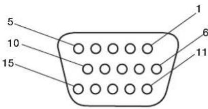
Mini D-SUB 15P
3) RS-232C Input (D-SUB 9P)
| Pin No. | Name |
| 1 | Connected to 7 & 8 |
| 2 | RXD |
| 3 | TXD |
| 4 | Connected to 6 |
| 5 | GND |
| 6 | Connected to 4 |
| 7 | Connected to 1 & 8 |
| 8 | Connected to 1 & 7 |
| 9 | NC |
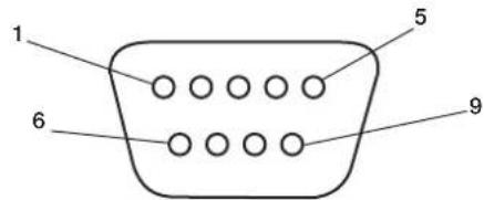
D-SUB 9P
2) Digital RGB Input (DVI-D) DVI
| 1 | TX2- 9 TX1- 17 TX0- | ||||
| 2 | TX2+ 10 TX1+ 18 TX0+ | ||||
| 3 | Shield (TX2/TH4) 11 Shield (TX1/TH3) 19 Shield (TXP/TH5) | ||||
| 4 | N C 1 2 N C | 2 0 N C | |||
| 5 | N C 1 3 N C | 2 1 N C | |||
| 6 | DDC-Serial Clock 14 | +5 power | 22 | Shield (TXC) | |
| 7 | DDC-Serial Data | 15 Ground (+5V) | 23 | TXC+ | |
| 8 | NC | 16 Hot Plug Detect | 24 | TXC- | |
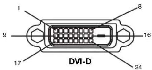
American National Standard for Human Factors Engineering of Visual Display Terminal Workstations ANSI-HFS Standard No. 100-1988
Veröffentlich vom:
The Human Factors and Ergonomics Society P.O.Box 1369, Santa Monica, California 90406.
Canadian Department of Communications Compliance Statement
American National Standard for Human Factors Engineering of Visual Display Terminal Workstations ANSI-HFS Standard No.100-1988
aio: The Human Factors and Ergonomics SocietyP.O.Box 1369, Santa Monica, California 90406.
Evaaooi tic pvthetaic eikovac a to 1 ec6 to 6.
POWER
Tua va evepyoonouoet / aevepyoonoiotnv oovn:
H eKov a 8v Ee to owoTo eYe0c
Xpnouonoiote ta xeiipotnpia OSD yia va auEnoe Tva tic pvthetaic.
Bebaiowtei 0xexe iAeyei kataoan oovotnpic nOtvkapta oovnc nOTo oovtnma nov xpnauoioietai. (iaaota to eyyepidio xphons nKaptac oovnc nTov ovotmuatoc yia va aalaleTe nTv kataoan twyypapukw.)
H eIaeyevn avalvon 8ev uqavicetau ootá
Xpnouonnte nnpopopoeC OSD ia va mte sto evovn npopopwky eipbaowot otexi eaiyei no wot anavluon. Eav dev exiyiveauro, eiaeTe tn owtn avalvoan.
v p i xo
ElambdaetyTeTcovvdeoeictwynxieiwv.
ELeyTe mwnoc n aeitovpyia anouovwnc hov evan eevpyoiouev.
ELeyTe mwnoc n Evtaon nXov eivai pvthetayn oTo EaXoH. HMEIΩΣH: Eivai duvato va avanapaxei nxoc aOdeltaopetiknnyn ektoa oTo bivteo.
H RS-232C Aetovpyi
American National Standard for Human Factors Engineering of Visual Display Terminal Workstations ANSI-HFS Standard No.100-1988
Publicado por: The Human Factors and Ergonomics Society C.P.1369, Santa Monica, California 90406.
Limpiar el Panel
American National Standard for Human Factors Engineering of Visual Display Terminal Workstations ANSI-HFS Standard No.100-1988
Publie par: The Human Factors and Ergonomics Society P.O.Box 1369, Santa Monica, California 90406.
Active/désactive I'OSD.
9) ▲▼
American National Standard for Human Factors Engineering of Visual Display Terminal Workstations ANSI-HFS Standard No.100-1988
Publicicato da: The Human Factors and Ergonomics Society P.O.Box 1369, Santa Monica, California 90406.
IeHTnKauy npbTa nctaHOnHO npaBHeNpy. Pycckn-13
Ponck uyctpaehne HncnpabHocTei . Pycckn - 14
BaxHbIe HnCTpyKcN IIO TexHnke 6e3OpaCHocTn
IpoHTaIte IpeE 3KcIIyatauHnei o6OpYIOBaHn.
- IpoHTaTe 3TN HnCTpyKuHn.
- CoxpaHnTe 3TN HnCTpyKnn.
- 06paTHTe BHMaHHe Ha BCE IpeJyIpeKJeHnA.
4.CnEynTe Bcem HNCTpyKUNM.
5.HeHcIOJIbayIte3TOyCTPOJcTBOB6n3NBObl. - Ipn ouHCTKe HcnoIb3yIe ToIbKO cyXIO TKaHb.
7.He 3arpaKaJaTe BeHTnIaIOHbIe OTBepCTNIA IIpon3BOIDte yctAHOBky B COOTBeTcTBnC INHCTpyKIIIMM IIpon3BOIDTEJI. - He yctaHaBnBaIte B6JH3N NCTOuHKnOB TeIIa, HauPmep 6aTapei, o6oRpeBaTeJIe, Iueei JIN JpyTuX yCtpoIcTB (BKIOyA yCNIITeI), KOToPbE BBpa6aTbIBaIOT TEIIIO.
9.He hapyiae 3aunTy IIOJepn3ObaHHo HIN 3a3EMHHOI IIITeNCbHOH BNIKN.Ha IIOJIpyn3OBAHHO IIITENCbHOH BUNKE HAXOJTCB IBA KOHTAKTA, OINH N3 KOTOPBX IIIMpe DpyTORO. 3aEMHeHHa IIITENCbHbA BUNKa OCHaIIeHa DBYMa KOHTAKTMN 3y6IoM 3a3EMHeHNA IIIpOKn KOHTAKT N 3y6eI3a3EmHeHNA IIpeHbA3HaueHb IINo6ecIeHn 6eONacHOCTN IOJIb3OBaTeJI.EcIN IIITEncbHbA BNlKA He BCtABIneTcB CceByIO PO3ETKY, INI 3aMeHbI yCrapeBWeip03ETKn O6paNTecbK 3JIeKTPNK. - IpoIoxKnte ceteBOH IIHyp TaKIM O6pa3OM, YTO6bI erO HeJIb38 6blIO 3aIIeEMnTb Hr HA HeRr HeJIb38 6blIO HaCTyINrTb, OcO6eHHO y IITeNceJIbHOB BNIKN, PO3ETKN IN B MeCtRe, ITe OH BIXoINT n3 YCTPOINCTBa.
- NcnoB3yTe TOIbKO KpeIIeHn/IIpHaJIeKHOCTN, yKa3aHHBe IIPOU3BOJNTeIeM.
12.ИПОЛБ3уTeToIbKOcTeIeKko,CTOIOK, TpeHOrO, KPOHIITeHOM HIN CTOLOM,yKa3aHHbIM Ipon3BOJNTeIeM HIN IIpoDAHHbIM BMeCTe C yctPoIcTBOM.BO 36ExaHHeIOnyueHnTpaBMbOT OIIpOKNDbBAHn IIpi NCIIOJIb3OBaHHn TeLEeKKn 6yNbTe ocTopoKHBIpne ee IepMeIeHNm INI IpepMeIeHNn HeCKOJIbKNx YcTpoIcTB.

- OTKIIOUaIte yCTPOINCTBO OT cTeBOI PO3ETKN BO BpeM rpo3b, a TaKKe, ecII NHO He IcIIIOJIb3yeTcB TeueHne IIITeIBHO BpeMeHN.
14.Bce 06cIyKbAHn IOLJHcO cYJIeCTBJIaTbcN KBaIIINpOBaHHbIMn pa6OTHNkAMN. O6cIyKbAHn Tpe6yETc IIpi IIO6OM IOBpeKdEHnn YcTPOiCTBa, HApIMep IIpi IOBpeKdEHnn IIIHypa NCTOuHNKa IIITaHn IIIN IIITeNCJIbHO BUNIK, IIOJaADHMn KINKOCtN (IOXJB) ININ IIpeDMetOB BVcTPOiCTBO, HePpABINbHOI pa6OTE ININ PAdeHNN.
IIOIOINHTeJIbHaN HΦOpMaIIH N0 6e3OIIaCHOCTU
15.ДанhoeH3dJIeMoKTeCoIepKaTbCBNHHeU. YTNIN3aIIINIOO6HbIXMaTePnaIOBperyInpyeTcN 3KOIOrueckMmCOo6paKeHHMaMn.
IIIIOIyueHnIHOpMaunIIO yTIN3aunnn IINI nepepa6OTKe 06paTneTecb MecTHbIe OpraHbI BIACTN IIN Co103 KOMIIaHn EJIeKtpoHHOtPacIn IIO aDpecy www.eiae org.
16.Повpeждени,тpe6уюшee 06слукиBaHHa, -obcIyKnBaHne IOJIxHO OcyIeCTBJIaTbcK BaIIHΦNIIpOBAHHbIMn pa6OTHmKaMn B cIeIyIOIux CnyuaX.
A.IIOBpeKJdeH IIIHyp NCTOCHKA INTAHNIA IINI
IITEENCEJIbHaB BNJa.
IIIN
B. BycTpoiCTBO IIOIaIIN IIpeIMetb IINI KIKOCTb.
IIIN
C.YcTpoIcTBo IOnaIO IOJIOJXJB. H
D.YcptpoCTBOpa6oTaETHeIpaBnIbHOHIN IpOABJIeTc3HaHTeJIbHOeN3MeHHeBpa6OTe. HII
E.Пюизошлп паденге устpoиства ИИ ПОВпждн Корпс.
- HaKIOH/yCTOuYBOCTb - Bce MOHITOpbI DOJIKHbI COOTBeTCTBOBaTpeKOMeHNyEMbIM MeKJyHaPOIHbIM cTAHJaPTaM 6e3OIIaNcHOCtN IIO CBOIcTBaM HaKIOHa N yCTOuYBOCTn KOHCTpyKUnN KOpNyca.
He HApyHaaTe DaHHbIe CTAHdApTb KoHcTpkyuHnnyTem PnpMeHnHa Ype3MepHBx TAnHyuX yCNmK IpeDHe nn BepxHe NacTm KopNyca, np KOTOpbIX, B KOHeHOM ChTe, MoKeT IIpon3OHTN OIIpOKnBbAHne 13JeHn.
Kpome TOrO, He KlaIaIte Ha BepXHIOU Yactb KopIlyca 3JIeKTKPOHHBe yCTPOnCTBa/ITpyIIKN, TEM cMbIM IIOBepra OIacHOCTN ce6n INI DeTei.
Takne IpeIMeTb MOryT HeOxNlaHNo yIaCtb C BepXHei
Yactn YcTPOcTB N IIpNBecTN K IOBpeKdEHNIO
H3JeIMN INI NOUYeHNIO TpaBMbl. - KpeIIeHne Ha cTeHy/IOToIOK. YcTpoIcTBOMKHO 3aKpeIITb Ha cTeHe TOIbKO B COOTBeTCTBUN C peKOMeHNdaIINMn IPOUN3BOIDNTeJIa.
- INHIN 3JIeKTPoNEpeJaH - HApYKaHa aHTeHHa IOnJKApaacnolaraTbca BdaHr OT INHIN 3JIeKTPoNEpeJaH.
20.3a3eMJIeHHe HApyKHO aHTeHHb -ecn HApyKHaa aHTeHHa IIOKIIIOHeHa K IIpneMHNky, 06a3aTeIbHO 3a3eMInTe aHTeHHyIO CnCTeMy TaK, YTO6bI O6ecPiNTb 3aIITy OT cKaYKOB HAIPJKeHHN N O6pa3OBAHHN 3JIeKTPOCTaTNUeCKNX 3apJIOB.
Pa3dien 810 haHnoHaIbHbIX npaBnI yctaHOBNK
JIeKTPPOO6OpyIOBaHN. ANSI/NFPA B IokymHe N9
70-1984 coepKNTcN HΦopMaunio HaJIeKaIeMy
3aEMJIeHNIO IOCTaBOK N OIOpHbIX KOHCTpyKUN,
3aEMJIeHNIO BBOIHORIO IpoBOJa ycTPOINCTBA pa3pJKN
aHTEHbI, pa3Mepy 3a3EmIAUx pa3bEMOB,
paIOIOXeHNIO YcTPOINCTBa pa3pJKN aHTEHbI,
IOKIIIOyeHNIO K 3a3EmIAIOUM 3JIeKTPoJaAM
Tpe6OBAHN K HIM.
21.IIopaaHHe IpeMeTOB H KNUKoCTn-Co6IIIOaJIte octopoXHOCTb,HTO6bI He yPOHNt bIpeIMTeBnHE IIPOINTB BOy B KOpNc Ype3 OTBepCTnI.
Ha yctpoIcTBO He IOJIKHa IPOcaHbTa cNII pa36pb3rHbTaCBA. KaPMe TOrO, He CTaBbTe Ha Hero IIpeDMtBi C KINKOCTbIO, HApIMep Ba3bl.
ПЕДУПЕЖДЕНЕ
YTo6bI yMeHbIHTb PNCK BO3ROpAHN HIN NIPAKeHN 3JIeKTPnueckm TOKOM, He IPOJINBaIte Ha yCTPOIcTBO BOy H He OCTaBIAITe erIOI IOXdEM.
PPEyPExEHE

BO N36EKAHNE BO3TOPAHINI IIN IIOPAXEHNIA 3JIEKTPUHECKIM TOKOM HE IIPOJINBAITE HA YCTPOICTBO BOY IN HE OCTABJITTE ETO IIOI JOKIEM. HE NCIOJIB3VITE IIOJIPIN3OBAHHVIO IIITECEJIbHYO BNIJKV 3TOTO YCTPOICTBA C PO3ETKON YIINIHNTELI INI INI DYTUMN PO3ETKAMN, ECIIIN 3YBUHHEBO3MOKHO BCTABITB IO KOHIIA.

HEOTKPBIAIIEKOPIIYUC,IOCKOJIbky BHYTPN HERO IMEOTC KOMIOHEHTbI, HAXOJIINIECEIIOJI BBICOKIM HAIIIPXKEHNE.MOBCLYIKBAHNE IOJIXHO OCYIECTBJIITbC KBAJINPHPOBAHHbIMPABOTHIKAMI.
BHIMAHNE
BHIMAHNE:

YTOBbI YMEHbINTb PNCK IOPAXEHNRAJIKTPNUECKIM TOKOM, YBEJNTECb, YTO CETEBO IIHYP HE BCTABIEH B PO3ETKY. YTOBbI IIOJIHOCTbIO OBJECTbYCTPOINCTBO, OTCOEIINHITE CETEBO IIHYP IN3 PO3ETKN IEPEMEHNO TOKA. HE CHIMAJNE KPBIIIKV (ININ 3AIHIO CTENHK). BHYTPN UCTPOINCTBA OTCYTCTBYOT JETALIN, OBCJYKINBAHINE KOTOPBX MOKETOCYIIIECTBITcBIOJIb3OBATEJEEM. OBCJYKINBAHINE JOJIXHO OCYIIIECTBITcB KBAJINΦIINPOBAHHbIMN PABOTHIKAMN.

JaHHbI cHMBON HIOHOBJyETcH IINI INeYIpEeKJHn HIOB3OBaTeHn O HAINuHN HaEN3OJIPOBaHHbIX
JeTaJHX BHyTPN yCTPoNCTBa HAnPjaKeHn IOCTaTOHn BeINuHN IINI OIPAKeHn 3IEKTPnueCKHM TOKOM.
CJeIOBATEbHO,IOtpaHbATbcN IOIO6oBIO DeTaN BHyTPn yCTpoNCTBa ONaCHO.
JaHHbI cHMBON HIOHOBJyETcH IINI INeYIpEeKJHn HIOB3OBaTeHn O HAINuHN BaxHoN IInTEpaTybl IIO
3KcIIpyataunn N O6cIyJKNBaHnIO DaHHoro yCTpoNCTBa.CJeIOBATEbHO,BO H36eKaHne IpO6JIem ee Heo6XoIMMO
BHUMATEbHO IIPOUHTab.
BHIMAHHE: NcnoIb3yIte cTeBOH IIHyp, NOCTaBIIeMb C JaHHbIM IINCIJIeEM, B COOTBeTCTBHN C IIpNBHeEHHO HNKe Ta6NIueH. IIPI OTCYCTBHN B KOMIIIEKTE cTeBOrO IIIHypa 06paNTecb KIOCTaBUNKY. BpyTNX CIyuaX NCIOJIb3yIte cTeBOH IIHyp, KOtOpBpI paccHTaH Ha HAnpJxKeHne IepMeHHORo TOKa cTeBOH PO3ETKN, IPOBEpeH IN COOTBeTCTByET CTAHApTy Be3ONAcHOCtN KOHKPeTHOH CTpaHbI.
American National Standard for Human Factors Engineering of Visual Display Terminal Workstations Cmandapm ANSI-HFS No 100-1988
Ony6nKoBaHo:
The Human Factors and Ergonomics Society P.O.Box 1369, Santa Monica, California 90406.
OuInctka NaHeJIa
- Pn 3aPra3HeHnn NaHe nn cKoJIeHN Ha He nn octopoXHO IpOTpTe ee MAnKo TKAHbO.
HeTpnteIaHEnbIpy6bIMMaTepeHaIaMn.
He IaBnTe Ha IOBepXHocTb.
He nIOJIb3yIte YnCTTae cpeICTBO OA.Ipn erO IcIOJIb3OBAHm MOKHO IOBpeNTb NIN 06ecIeBETNb IOBepXHOCTb.
Ounstka Kopnyca
OTKIOUHTNEICTOUYHKITNAHIA.
- Octopokho IIpoptpTe KopIyc MraKoT KaHbIO.
TO6bOuHCTHTB KOPITCMOUHTKaHB BBOIE C HeITpaJIbHbIM MOIOIIM CpeIDCTBOM, IPOPTPte KOpITc, a 3aTeMeEe pa3 IIPOPTPte erO cyXoTkaHbIO.
IIIPIMEUAHNE: IIOBepxHocbKOpNyCa cocToNT n3 IIACTMaCCbI pa3JIuYHbIX TNIIOB. HE BbIIOJIHNrte OUnCTKy C IIOMOUb6eH3OIOBOrO pactBOpHTeJI, IeIooHOrO MOIOIeO cpeICTBa, MoIOIeO cpeICTBa co CINrTOM, OUnCTTeJI dJIa CTeKOI, BOCKa, IIOIIpOJI, MblbHOrO IIOPOIIka IIN NHCeKTNUINHOr OBeIeCTBa. B TeueHne IInITeJIbHOrO IEPNOda BpemeHn Pe3NuHa IIN BUNNl He IOJKNb KOHTaKTIpOBaTb C KOpIycom. TaKHe TNIb JxIKoCTeI INM MaTePnaIOB MOrT IprNBecTI K IOPYe, IOTpeCKNbAHnIO HIN OTcIaNBAHHIO KpaCKN.
OuNCTKA BEHTNJRAUHOHBIX OTBEPCTNI
OuHuaIe BeHTnJIaIOHbIe O6JIaCTn IJIa3MeHHOro MOHITopa C IIMOIOBIO IIbIIEcOCa CMrTKoI ΜEeTKoI.
- IJIa o6ecIeueHnI npaBnIbHO BeHTnIaIIuBBIIOJIHnTe OYNCTKy BEHTnIaIOHHbIX 06IaCTeKakJbIM MeCn. B3aBnCmOCTn OT cpebl, B KOTOpouYCTaHOBJEN IIa3MeHHbM MOHITOP, ONUCTKY MoKeT IOTpe6OBaTbCBAIIIOHNrTB 6oJIee Yacto.
IpeodTbpaueHne NOBJIeHn IJN CHNXeHne 3oOpeKta OCTaTOUHorO N3O6paXeHn
Takke KaK IIO6bIe MOHITOpbI c focOphiBIM NOKpbTHeM INI IpyTne Ra3opa3PdIHbIe IINCIIIE, B IIa3MeHHbIX MOHITopax IIpN OIIpeJIeJIeHHbIX BO3HnKaet 0cΦeKT OCTaTOUHO r3o6paJKeHN. HeKOtOpbIe yCIIOBNI KCIyATAuIN, HAnpIMep OTO6paKeHNe CTATNUeCKORIO I3o6paKeHNr B TeueHne IIPOIOJIKNTEJIbHO rIO pOMeKytKa BPemeHN, MOrY T PnIBeCTN K BO3HnKHOBeHNIO 0cΦeKT OCTaTOUHO r3o6paKeHN, ECINr HE IIpeIIPnHHTbI COOTBeCTByIOUme MeBIs PpeIOCTOPOXHOCTN.IIra 3aIHTbI IIaIA3MeHHO rMOHITopA OT 0cΦeKT aOCTaTOUHO r3o6paKeHNr Co6IOJaTe CInyIOUne IHCTpyKIIIN n peKOMeHDAuHN:
- IIpn HcIOJIb3OBAHHM MOHITOPa C KOMIIbIOTepOM BcERJa BKJIIOUaHTe Ha KOMIIbIbTepe 3KpaHHy0 3actABky.
IIO BO3MOKHOCTN BOCIIPOH3BOJNTe IBNrAIOJIeecn 306paKeHne.
BpeMg OT BpeMeHn H3MeHnTe IIOIOKeHne 3KpaHHORo MCHIO.
Iocne NcIOJIb3OBaHHaMOHITopa BceRda BbIKIOuHaTeero.
UmehbweHne BepoTHocTn BO3HnKHOBeHnja 0peKta OCTaToCHoro n3O6paXeHn npnpoJoxKeIbHOM NCNoJIb3OBaHn
YMeHbIInTe yPoBeHb JPKoCTn N KOHTpaCTHO MIMHMajbHoN OTMeTKN, IIPI KOTopoN H3O6paKeHne OCTaETcYETKm.
- OTo6paKaJte MHOrOuBcTHbIe N3o6paKeHnco MHOKeCTBOM OTTeHKOB (HaIIpUmEp,ΦOTOrpaΦHn NIN ΦOTIOIO6HbIe N3o6paKeHn).
C03daTe H3O6paXeHHe C MHNMaJIbHOI KOHTpactHOCTbIO MEKJy CBETbIMN I TeMHbIMN 06JIaCTaMn. IIO BO3MOKHOCT N CIOJIb3yTe IOIOJIHNTeJIbIIbIe INI NaCTeJIbIIbIe IBeTa.
CtapaTecb He OTO6paKaTaBc H3O6paKeHnnc He6oJIbIIMKoINueCTBOM IBeTOB NHeTKOBblpaKeHHbIMrpaHNiAmM MeKdy IBeTaMn.
3ByKn, BO3HnKaIOuIne np paBoTe MOHTopa
IIaHeIb IIa3MeHHOro MOHITopa COCTOHT I3 NIKCeIOB BbICOKOI IOIOTHOCTN, KOTOpBE I3JIyuaOT CBET B COOTBeTCBN CIOJyuaeMbIMN BUNDEOCINHaIAmN. IIO3OMy Ipr pa6OTE IIa3MeHHORo MOHITOPa MOxHO YcblIiAtb JyKkaHne IINrIydeHne.IMeTe B BNy, TTO yBeIInuHm TEMIIepaTpybI Ila3MeHHORo MOHITopa CKOpocTB BpaIeHnO XIAkDaIOIeRO BeHTNIATopa yBeINuHBaetc. B TaKHe MOMeHTb CbIHIEH IIIyM IBNrataJIa.
IIIPIMEUAHHE: IapaHTnHe paacPiocTpaHReTcHa.
- ΘΦΦeKT OCTaToCHOrO N3o6paKeHnI
3ByKN,NCIyCKaEMbIe IaHeJIbIO.
PiMepbI:IBnIraTeIb
BEHTNIATOPaOJIeKTPuYeCKNe IIYMbI,
ryJeHneB3eKTPuYeCKNXIeIIAX/
JyKKaHneCTeKJIaHHoIpaHeJI.
UCIOBNA 3KcPlyATAUIN
TeMnepaTpya INBlaJXHOCTb OKpykaIOIIe CpeIb:OT 0^ 10 +40^ (OT +32^ 10 +104°F);OTHOCTeJIbHna BIAJXHOCTb BO3Jyxa MeHee 80% (OTBepCTnIg IJIaIXeHNHa He 3a6IOKInPOBaHbI).He pa3MeIaIteYcTpOcTBo IBIOXo BEHTNINpyeMoO O6JIaCTn, B MecTAX C BBICOKOI BIAJXHOCTbIO IIN IIoI pIpaMbIM COJIHeuHbIM JUyAmN (IOID CNJBHbIM NCKycCTBeHHbIM OCBeIIeHNEm)
PPEyPExKdEHN
He IINIOB3OBaHn B MaIIHHOM 3aIe corIacHO ctAnapry Protection of Electronic Computer/Data Processing Equipment ANSI/NFPA 75 (3aIIHTa 3JIeKTPoHHOrO BbYNCINTEbHOrO o6OpyOBaHn/ 06OpyIOBaHn 06pa6OTKn DaHHbx).
IIIPIMEUAHNE: IVcIOJIb3yIte 3KpaHnPOBaHHb Ka6eJIb BUNDeOcINrHaJa ot 15-KoHTaKTHO rpoa3beMa mini D-SUB K 15-KoHTaKTHomy pa3bemy mini D-SUB c feppntOBbMn cepJeHNkamn Ha o60nx KOHcax (He BXODIT B KOMIIeKT IocTaBKN).
IcnoJb3OBaHne DOONHHTeJIbHbIX CTOeK/ KpenJIeHn
KorJa MOHITOP HAXOINTCB B BEPTNkaJIbHOM IIOJOKeHNn IINI JEXNT IINCEBOI CTOPHOB BHUN3,MOXHO IIpIKpeINTb IOIOHNHTeHBHyO CTOnKy INN KpeIIHeHne.
IIa KpeIeHnA CToIKN, KOrIa MoHHTOp HaxOITcB B BePTIkaIbHOMIOIOXKeHH, OINCTte MOHTOp Ha IOCTaBky (Pnc. 1). YIepKNaBaTe IINCIIeN 3a pyKn, KOrIa ONyCKaTe erO OTBePCTNIM B HmKHe Nactn Ha IOCTaBky.
KorJa IIaHInpyETcYCTaHOINbCTOINKIIN KpeIIeHne,a yCTPOINBOIIN3OM HAnPABIEHOINCEBOI CTPOHOIN BHN3 (Pnc.2),BO IN36ExKaHHeIOBpeKJeEHN3KpaHa 063aTeJIbHO IIOXHTeIOI Hero 3aIITbIbI NCT (NEHOINACTOBHINCT, B KOTOpBb6bIIO 3aBepHyTo yCTPOINCTBO).
JaHHoe ycTPOINCTBO JONJHO HNCIOJIb3OBaTbc8 CO CTOnKOHN KpeINIEHmKAKOHO TnIIa. JaHHoe ycTPOINCTBO He IpeHa3HaueHO JIA NCIIOJIb3OBaHn6e3 IOIOHNTEbHO ONOpbl.
IIO6eCIIeHINIIpaBnIbHOYcTAHOBKn I KpeIIeHn peKOMeHNyTeCN O6paNTbcN KO6yHeHHOMy ABTOPN3OBaHHOMy paNpOcTpaHNTeII.
Ipn Hec6bHIOeHN IIPOeDpy IpaBnHoro KpeIIeHN BO3MOxHO IOBpeKJeHne yCTpoiCTBa HIN IOnyHeHne TpaBMbYcTaHOuNkOM.
IapaHTnH3eJIHHe paCnpocTpaHAreTcHa HOBpeKHeHne,IIpon30WeDiWee B pe3yIbTaTe HePpABnBHOYCTaHOBKn.
BHUMAHNE:
-ⅡBbHIOHEHHyYCTAHOBKnCneIyTe HNCTpyKIIHM, KOtOpBle IIpIINaIaOTcK CToIKe IIN KpeIIIEHHIO. NcIOJIb3yIte ToIbKO yCTpoIcTbA, peKOMeHIOBaHHbIe IPOUN3BOJNTeIeM.
IpyuYCTAHOBKe CTOKIN NIK KpeIIeHnO63aTeBHO paIOIOXkNTe YCTPOIcTBo HA KpeIKoN IyCTOuNBOI IOBepxHOCTN, cIOco6HO BbIepKaTb Bec yCTPOIcTBA, HApPIMeP NOly INI INPOOHOM CTONE.
-ДяуCTaHOBKn HcIOJIb3yIte yKa3aHHHbe 3aJKNMbl.
Bo 36eKaHHe OnpOKnBbAHn HnPi NaEHHyctpoiCTBa BblONIHHTe Heo6xoIMMbIe JeIcTBnA.
MecToIyCTaHOBKn
IOTONIK N CTeHa IOnKbI 6bIT bOCTaTOHc KpeKNMn, YTO6b BbIepKaTb MOHTOP IN IIpHaJIeXHOCTN dIN KpeIIeHH.
HEyCTaHaBnBaIteYcTPOINCTBO B MecTx, Ie erOMory3aIeTB IIbep HIN BOPOTa.
HEyCTaHaBJIbAaTe yCTpoNCTBO B MecTax, Ie Ha HrO 6yET BO3JeCTBOBaTcIIbHaR BnOpaIIN IIbIb.
HEycraHabnBaIteyctpoNCTBO6n3MeCt,1e OCHOBHOH NCTOHTHK INTaHIMIOINXoINT K 3daHNIO.
HEyctaHaBnBaIte yCTPOINCTBO B MecTAX,1e Ha HEM IIN HA KpeIIeHm MOrTy IOBnCHyTb IIOIN.
IIpyuCTAHOBKe BIIKafNnYrIy6neHne (KaK, HApnpMep,BCTeHe)IOObecIeHnHaIeXaIeBcHTINJIIMMeKJyCTeHOINMOHITOPOMOCTaBBte paCCToRHNHe MeMeHee 2IOHMOB(50MM)(Pnc.3).
06ecnuebTeIOCTaOHTHyOBENTNIAUIO NIKOHmIOHNPoBAHNA BO3yxa BOKpyr MOHITOPa,TO6bI TeIIIO OT yCtpoiCTBa N KpeIIeHHpaaccenBaIOCBdoJKNbIM 6pa3OM.

Pnc.1
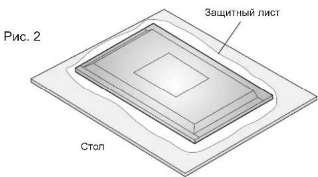
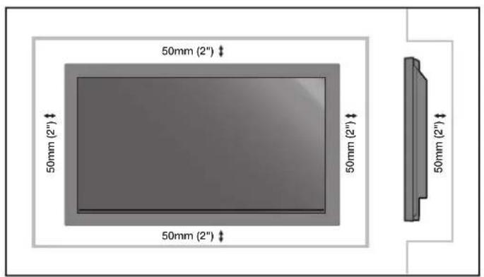
Pnc.3
YcTaHOBKa Ha IIOToJIke
Y6eHNTecb,HTO IOTOKIOCTaTOUHOIPOuHbI, YTO6bBbIepKaTb BcC yCTPOICTBaN KpeIIeHnB TeHeHne IINTEJIbHO BpEMEH N pN 3eMJIeTpCeHnx, BHe3aIHbIX Bn6paun N IPOuHX BHeHHX BO3JIeCTBHX.
Y6eINTecb, YTO yCTpOHTBO KpeHNTcHa HIOPOHON KOHCTpyKUNB IOTOnKE, HAIPIMep Ha OIOPHo 6aJIKe. 3aKpeHNTe MOHTOP C IOMOUBo 6oITOB, IpyKHHbIX N O6bUHbX IIIaIbN rAaKN.
HEOCyIeCTBnIteYcTaHOBkyBMecTx6e3 BHyTpeHHeOnOpHNoKoHCTpyKuHN. HE NcIOJIb3yTe IJI KPeIIIEHnI IUPyIIbIuAnKKePHbE BuHTbI. HE yCTaHaBnBaIte YcTPOIcTBO HaOTJeIKy INI CBnCaIOIIne KPeIIIEHnI.
O6cIyJxNBAHne
- IepnoDnueckn IpoBepHne Ocna6HHe BnHTbI, Hcnn, NCKpNBHeHn Hn npyTne Ipo6nEmb, KOtOpbE MoYr IPOu3oHTn C KpeHnHeHem. Pnp O6hApyKeHHn Ipo6nMbl 6opatnteck KBAHnOHNpOBaHOMy Pa60THKv Jn HIOBcHHeHn O6CJyKbHaHn.
PeyIaRHO IPOBepHte MeCTO yCTaHOBKn Ha IIpN3HaKN IOBpeKJHeHn HIN Ocna6eBaHHN, KOTOpbE MOryT IPON3OHTn CO BPeMeHem.
Ipn MoNTaKe Ha cTeHy mIII IIOToJOK IMeIte BBnDy cIeIyIOIe
IIpn HcIOJIb3OBAHn HpHaIeXHOCTeI Jn MOHTaKa, KOTOpBie He 6bln OIO6peHb KOMIIaHnei NEC,y6eITecb, YTO OHn COOTBERCTBYOT MeToy KpeIIeHHa, COBMeTtMOMy c VESA (FDMly1).
KOMIIaHnNEC HAcToTeJIbHO peKOMeHJyET NIOIb3OBaTb BHTbM8 (16 MM + TOIIINHa KPOIHITHeHa).Ipiu NIOJIb3OBAHHBnHTOB,KOTOpbIE IINHHe 16 MM,IPoBepBe rIy6nHy OTBepCTnA (peKOMeHIOBaHHoe ycInHe:1125-1375H·cm). KomIIaHnNEC peKOMeHJyET nHTepfchk KpeIIeHHN,KOtOpBte COOTBEcTBYiot cTAHApTy UL1678 (CeBepHa AmePka).
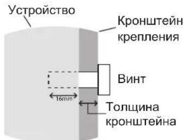
JINHa BnHTa DOJNKHpaBnHbCnRrny6nHe OTBepctn(16MM)+TOnuHa KPOHHTeHa KpeJIeHna.
OpneHTaH
HE NCIOB3yTe MOHHTOP B KHNKHom IOIOKeHHN. B IPOTNBHOM CNYae MOKET BO3HNKHYtB HeNCIIpaBHOCTb, a rapaTHn6yEt aHHIpObaHa.
YklaIka Ka6eIeI
Jyno6Hou yKaJaKn Ka6eJe HcNoB3yIte 3aKmbl, IpeHa3HaueHHBe JIA CB3KN CeTeBOrO IIHypa C Ka6eJIaMn CnHaJa N ayDnOKa6eJIaMn B 3aHHe Yactn DnCIIe.
KpeIIeHHe Ka6eIbHbIX 3aXIMOB:
1.ПикpenITE Ka6eIbHbIe 3aKIMbI K nCnIeIc. BCTaBBte KapaONH 3aKIMMa B OTBepCTHe Ha 3aJIHe Nactn IuCIIpeJ. J4 Ka6eJIbHbIX 3aKIMoB Ha yCTpoIcTbe HMeETc4 OTBepCTnIa.
2.Пocne paCIOIOKeHnKa6eJIbHOrO 3aKIMHa HINCIJIe O6MOTaIte KOHeII BOKpyr Ka6eIe.BCTaBBTe KOHeII 3aKIMBAOTBcPCTHe pJOM C Kapa6HOM.HATRnBaHTe, IOKa Ka6eHN He cTAYTCra.
3aKIMbI PpeHa3HaYeHb IINI ΦNKcaUNn Ha MeCTe. NocTe YCTaHOBKn 3aKIMOB INCNOKHO BbHYtB.
3. Ka6eJIM MOKHO IPOJOXHTb CIPAba HIN CNEBa OTRaXHMA. JIa cKeIIeHnA Ka6eJIIOBcEHN BceI INHe MCIOJIb3yITe CTJAKN.Y6eJNTecb,TO Ka6eJIN yDEpKJBNAOTcR IIOHOCTbIO
OTCOEINHHeHne 3aKIMOB:
C NOMOUIIOIIOCKORY6NEB NOBEPHNTe 3aKIM Ha 90 rpaIycOB IN BbITAHHTe eRO. C TeueHNEM BpeMeHN 3aKIM MOKeT OcIa6HyTB IN IIPIN I3BJIeEHIN ERO MOKHO IOBpeHNTb.
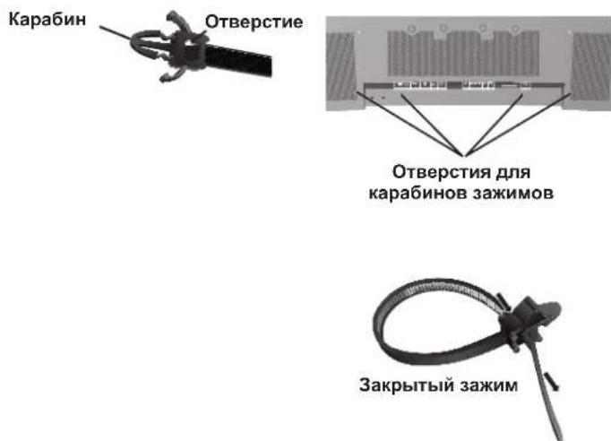
IcnoB3OBAHne IyIbTa IInCTaHIOHHOro yIpaBJIeHnA:
YcTaHOBtSe 6aTapeKn B NytB TmCTaHIOHOrO yIpaBHeHn.
IITaHHe IyIbTa IINCTAHIOHHORO yIpaBHeHnO cUyIeCTBJIeTcR O76atapeek AA. YTO6bI yCTaHOBTb HIM 3aMeHHTb 6atapeK, BblIOJIHTe yKa3aHHBe HNKe DeIcTBnI.
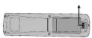
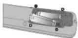
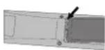
A. HaKMnTe n CdbuHbte KpbHkUy, YTO6bI OTKpbITb ee.
B. YcTaHOBNTe 6aTapeKn B COOTBeTCTBNN C o6o3HaueHnMaM (+) n (-) BHyTpN KOpPnCa.
C. YctaHOBNTe KpbIIKHy Ha MeTo.
BHIMAHHE: HenpaBnIbHoe nCIOB3OBaHne 6aTapeek MoKeT IIpNBecTN K yTeYkAM IIN B3pyIBy. KomIIaHHNE NEC peKomeHnyet nCIOB3OBaTB 6aTapeeKN cIeDyIOUIM o6pa3OM.
- YctaHOBtTe 6aTapeKn pa3Mepa AA TaK, TTO6bI 3HaKn (+) n (-) ha KaKIOH 6aTapeKe COBIIaJIn CO 3HaKaAMn (+) n (-) B 6aTapeHOM OTceKe.
He nIOJIb3yIte 6aTaapeKn pa3HbIX Mapok.
He nCIOIb3yIte cTapBIE HOBIe 6aTapeIKN, a TaKKe 6aTapeEKN pa3HbIX MapOK. Ppi NTOM MOKeT cOKpaNTbCe cPOK cnJx6bl 6aTapeek NIN IpnOImOnTn yTeUka 3JIeKTpoJIInTa.
Bo n36ekaHne yTeukn 3eKtpoJNTa B6atapeHOM OTceke cpa3y BbHbTe CEBHne 6atapeKn.
HeIOTparnBaTecbIO3NeKtpoNTa,IOCKOJIbKy OH MOKeT IOBpeNTb KOKy.
He poHnTe IyIbT nCTaHnOHHO yIpaBJeHHn I cIOJIb3yITe erO II Ha3HaYeHHIO.
IyIbT InCTaHIOHO yIpaBHeH He DOJIKeH IpomOKaTB. EcII Ha IIyIbT InCTaHIOHO rO yIpaBHeH NIOHaTe BOda, cpa3y BbITpnte erO Hacyxo.
136eraTe Upe3MepHOro TeIIaN BlaKaHocTn.
He BbIKMbIbAaTe 6aTaapeKnB OROhb. - PnyTIN3aunnncIOJIb3OBAHHbIX 6aTapeek CIEyIte IpaBNTeJIbCTBEHHbIM IOCTaHOBJEHNm INI O6IeCTBeHHbIM IpaBNIaAM 3aIITbI OKpyKaIOIIe cpebl, KOToPbIE DeIcTBYIOB CtpaHe/O6IacTN.
IIpn 3aMeHe NIOJb3yIe TOJIbKO O6bUHbIe HeIpe3apJaemBIE IeIOUHbIe INI MapraHIeBbIe 6aTapeKn.
IIpn HeIpaBnIbHOy yTaHOBKe 6aTapeek cyIecTByET OIIaCHOCTb B3pbHbA.
Pa6ouH mHaIa3OH IyIbTa IINCTaHIOHOHorO yIpaBHeHH
Ipi HaKaTHN KHOIOK HAnpaBJIaTe BepXHIOU qACTb
IIyIbTa IInCTAHIOHHORO yIpaBJIeHnHa DaTtNK
MOHTOPa.IyIbT IInCTAHIOHHORO yIpaBJIeHn MOJHO
HCIOJIb3OBaTB Ha MaKcIMaJIbHOM pacCToHnn 7 M/23 yTa
OT IpeJHeY qACTn MOHTOPa. OT IpeJHeY qACTn DaTtNKa
IINCTAHIOHHORO yIpaBJIeHn IIa3MeHHORO MOHTOPa.
MaKcIMaJIbHbIyTOI IO TOpH3OHTaII N BePTtKaII INp
HCIOJIb3OBaHHN IIyIbTa IInCTAHIOHHORO yIpaBJIeHn Ha
pacCToHnn 3,5M/11,5 yTa coCTaJIaET 30 rpaIycob.
BHIMAHHE
IyIbT IInCTaHIOHHORO ynpaBHeHn MoKTe He pa6oTaTb
IIpi IIOJaHaHn Ha JaTcNK IIla3MeHHoro MOHITopa
IpyMbIX COJIHeHbIX JUye HnN 60JIbHIoro KOJIneCTBa
CBeta, a TAKKe Iprn HaJIuHn IIpePapd.
O6paIeHne c IyIbTOM IINCTaHIOHOHor OIIpaBHeHH
OTkpBaIte IyIbI dIcTaHIOHO yIpaBHeHnToIbKO
IIra YCTaHOKn 6aTapeek.He IOnyckaIe IOnaHaHn Ha
IIyIbT dIcTaHIOHO yIpaBHeHn BOIb Hn IpyroJ
KIOKoCTN.EcIN Ha IIyIbT dIcTaHIOHO yIpaBHeHn
IIonoAET BOJa, cpa3y BbITpnte erO hAcYxo.
IV36eraIte BO3JeCTBnTeIIa n Iapa.
IIIPIMEYAHNE: Ecnn IyIbT InctaHIOHHORO yIpaBHeHn He IIaHpyETc HcIOJIb3OBaTB B TeueHne IINTEJIbHOcPOKa, BbIHbTe 6aTapeeKn.
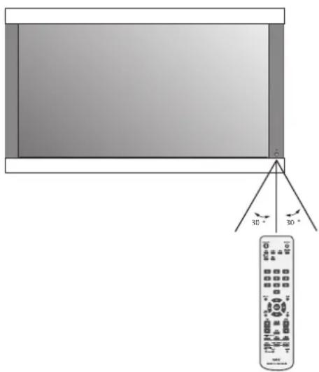

Ha3BaHnJaTeTaJeNФунКцИ
Panaelb ynpabJeHna
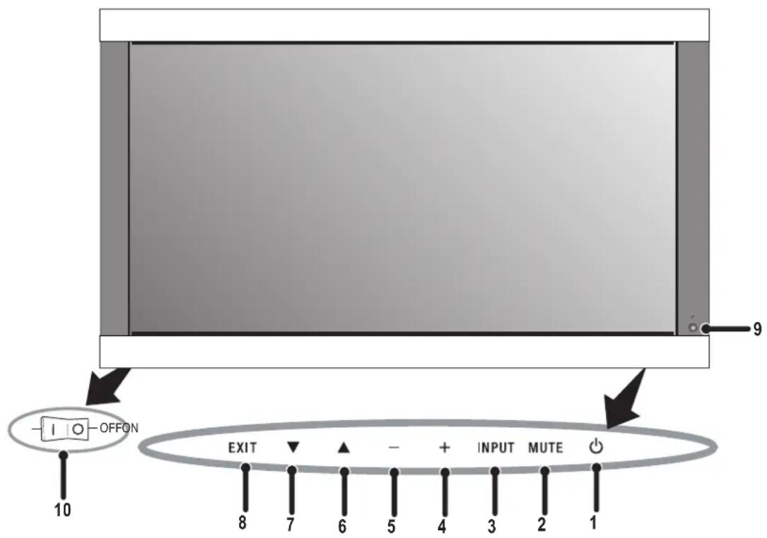
1)ПИТАНЕ
BkHueHeHne IITaHnI/epexoBpeKIM OKnJaHnI.
2)OTKJIIOUYEHNE3BYKA
BkIIOUeHne/ByIKIOUeHne 3Byka.
3) BXOⅡ
IpeekIOueHnIcTOuHKnOB BXoHOrO CHTHaJa.
JenCTByeT Ka KHOIIKa YCTAHOBKA B 3KpaHOM MeHIO.
4) IIIOC (+)
YBeIuHHe 3HaueHn npaMeTp aB kpaHHOM MeHIO.
5) MHHYC (-)
YMeHbIeHHe 3HaYeHnI NapaMeTpBa EKpaHHOM MeHIO.
6) BBEPX (▲)
YBeJIuHHe yPoBHa rPOMKoCTn,ecIIN 3KpaHHoe MeHO BbIKIOUcHo.
IpeMeHHe O6NaCTn BBepx IIN Bb6opa HAcTpaNBAEMO IpaMaTePa BKpaHHOM MeHIO.
7) BHN3 (▼)
YMeHbIeHne yPoBnI rPOMKoCTn, cCIn 3KpaHHoe MeHOBbIKIOyeHO.
IepemEeHHe O6JIaCTn BHN3 IINBbIb6Opa HAcTpaNBAEMOIO IapamEtpa B KpaHHOM MeHIO.
8)BbIXOII
BxOJ B 3KpaHHoe MeHIO,ecn OH OBO BbIKIooHeIO.
BbXoI N3 OTo6paKaemOro B HactoIIeepMeHIOHa MeHIO IpeIbIyIeTO yPObH B 3KpaHHOM MeHIO.
9) IATYIK INCTAHIOHHO YIIPABJEHNA IHJNKATOP IINTAHN
IpiHcHHaIa IpiN IcIOJIb3OBAHmN 6ecPiPoBOJHOI
IyIbTa IINCTaHIIOHHOYIIpaBJeHH. EcIM MOHTOP
BKIOUeH,ROPIT 3eJIeHbIM IBeTOM.EcIM MOHTOP
HaxoITcBpeKIMe OKIIaHH,ROPIT KpacHBIM IBeTOM.
EcIM MOHTOp HaxoITcB peKIMe YIIP.INTAHHE,
ROPIT JKeITbIM IBeTOM.
EcHIMHKaTOP NITaHHM MItaET KpaCHbIM UBeTOM, MOHHTOPOM 06HApyKeHa HEnCIIpaBHOCTb. B Cnyae BO3HNKHOBeHHN HeCNIIpaBHOCTn O6paTInTEc b K KBaHINΦHINPOBaHHOMy pa6OTHky.
10) TIAHBHII IPEKJIIOYATEJIb IITAHNIA
IpeKIOuOaTeB IyB KIOUeHn/ByIKIOUeHn IITaHn.
KhoIIka IIITaHnHe pa6OraT
- OToCoEHHHTe CTeBOH HHP MOHITOpa H3 PO3ETKn Cetu HepemEHOROTOKa, YTO6b BbIKIOHTb MOHITOp N C6pocHTb HAcTPOKN.
3ΦΦeKToocTaToCHOro H3O6paXeHHa
IIMETe BBNHy, YTO BIIa3MeHHoTExHOIOH cyueCTBye O06eHHocb, H3bBAemai 3ΦfKeTOM octatoHOrO N3o6paKeHH. 3ΦfKeT 3AKIOVAETCB TOM, YTO HA 3KpaHE octaetcraoctaoHoe N3o6paKeHHpeBbIyIeepTNHKn. BOTINuNEOTCRT-MOHHTOPOB, 3ΦfKeT OCTaTOHORO N3o6paKeHHB IIa3MeHHbIX MOHTOPax He ABJAEtCn HOCTOHHBM, ODAKO CIEyET 36eRaTB OTO6paKeHHe OHOrTOI TORe JI3o6paKeHHB TeeyHHe IOITROBpeMeHH. IJIyycTaPaeHHN 3ΦfKeTA OCTaTOHORO N3o6paKeHH BbIKIOHTe MOHTOP Ha BPema, paBHoe BpeMeHH OTo6paKeHHI PeBbIyIeero N3o6paKeHH. Hanpumep, eCN I3o6paKeHHe He MeHIAOCb HA MOHTOpB TeeyHHe yaca, IN B pe3yblate OctaetcraoctaTOHoe N3o6paKeHHe, BbIKIOHTe MOHTOP Ha vac, YTO6bI OHIO HCye3IO.
IIIPIMEUAHNE: KopnopaaunNEC DISPLAY SOLUTIONN peKOMeHNyET BOCnPOH3BcEHeHne IIOINBnKHOrO N3o6paKeHn H NcIOJIb3OBaHnE 3KpaHHoN 3acTbKN Yepe3 paBHbc IpomekyTKn BpeMeHN IINRA CEX INCInIeEB BCaIKN pa3, KOrJa INcInIe63dEChTByET. PeKOMeHNyETc TaKKe BbIKJUoyatb MOHITOP,ecn He NCIOJIb3yETcN.
H3o6paKeHne HeycToHnBOe, HecfoKycnpoBaHHoe HmCMeHaTcR
Ka6eIb BnIeocHTHaJIa OJIJIeH 6bITb HAJIeKAsIMo6pa3OM coeINHeCIIa3MeHHbIM MOHITOpM, KOMIIbIOTepOM INI npYrHM yCTPOBCTBOM BBOJa.
IcnoB3yHe cpeCTBa yipapBHeHn 3KpaHHbIM MeHO nHaCtpoKn fokycuPobKn u3O6paKeHNn nyTe mYBeJIHueHn Wn YMeHbWeHn Fa3b CnHXPOHn3aHn. PpN H3MeHeHN pekmApaoTb NcPiEe MoKeT Notpe6OBaTbCn IOHTOPHO HAcTPOHTb NapaMeTpbl 306paKeHNn 3KpaHHoro MEHO.
IIpoBepbTe COBmecTMOCTb MOHITOPa HnIaTHb IHCIIpe, a TaKKe peKOMeHdyEmBe CnIHJIbI CNHXPOHN3aUN.
1306paXeHne KOMIOHOHTHOTo CnTHaJa
3eHeHOBaTORO IIBeTa
- IIpoBepBe, BbI6paII IN BXOIOH pa3bEm DVD/HD.
He ropnt cBeToIONoHbI HnIMKaTOp
(HN 3eIeHbIM, HN KpaChbIM IBeTOM)
ΓIaBnI IpeKIOUOATEb IOJKeH 6bITb yCTaHOBJN B noIOKeHne BKJI, a cTeBOH Hyp - NOKIOUeH.
KpacbI CBetoIOIOHbI HINKaTOP Ha MOHTope MNTaeT
BepoTHO, pOn30IIeI c60i. CBrJXnTeCb c 6JINKaIIIM aTOpH3OBaHHbIM cepBnCHbIM ueHTpOM KopPiopaUN NEC DISPLAY SOLUTIONS.
Pa3Mep n306paXeHHa nHcIIee HacTpoEHIIpaBnIbHo
IcnoB3yTe cpeCTBa ynpaBHeHn 3KpaHHbIM MeHIO IyBeNueHn IIN yMeHbIIeHn NTOROBTO 3Haehn CNHXPOHN3aNN.
Y6eNTecb, YTO Ha HcNIOB3ayEmoH IIaTe DnCIIeR NIN CNCTeMb Bb6paII IOIepKnBaemb peKm. (IIJI IN3MeHENr rpaHueCKOrO peKMa o6paTntecb K pyKOBOCTBy IIOJIb3OBaTeH IIaTbI DnCIIeR NIN CNCTeMb.)
Bb6paHHe n3o6paXeHne oTo6paKaetc HnPaBnIbHo
IVIOJIb3yIte cnpaBky 3KpaHnHO MeHIO, YTO6bI BOHTN B MEHIO INΦOpMaIIIN N y6eIntecb, YTO BbIbpaHO COOTBeTCTByIOuEe pa3peuHne. B IpOTnBHom Cnyuae BB6epNTe IIpaBnIBHo pa3peuHne.
OTCyTcTBnE 3ByKa
- IpoBepBeIpaBnIbHocTbIOKJIIOUeHnKa6eJINHaMnKa.
- IIpoBepbTe, He OTKIOUoHEn IIN 3ByK.
IIpoBepbTe,He y6aBHeIeHn3ByKdoMmHmMyMa. IIPIMEYAHNE.MoKHO BOCIOPOH3BOOHTb 3ByKOT HCTOHNKA,OTNIHOROTBUNEOHCOTOHNA.
RS-232C He pa6oTaet
- IIpoBepbIe IapamTp YCTAHOBKA BMeHIO OyHKUJIA.
IyIbT IINCTaHIOHO HOrO yIpaBHeHn He pa6oTaE
Y6eITcB, YTO 6aTapeKIN BCTaJIeHb IpaBnJIbHO.
IIpoBepbTe 3apA6aTapeek.
Y6eNTecb,TOIyIbTINCTaHIOHOHor ynpabHeHH HnpaBHeH pIMo HA JaTnK MOHToPA.
IpoBepTe He HaxoINTcTn NINbT INCTaHIOHOY npABeHHN BpeKMe nEHTuKaUNyNbTa INCTaHIOHOrO ynpABeHH.
IyIbTnCTaHIOHO yIpaBHeHHe pa6Otae IIOI IpMbIM COJIHeHbIM lyuAMN II pN IIOHaHH 60JIbWoKOJIueCTBa CBeta Ha nCTaHIOHH daTHNK MOHTOPa.

No.70-1984, altiklarin ve destek yapisinin dokru topraklanması, kurşun bulunan kablonun anten-deşarj ünitesine topraklanması, topraklama konektörlerinin boyu, ante desarj ünitesinin yeri, topraklama elektrotlarina baglanti, ve topraklama elektrotu icin,...,...,...,...,...,...,...,...,...,...,...,...,...,...,...,...,...,...,...,...,...,...,...,...,...,...,...,...,...,...,...,...,...,...,...,...,...,...,...,...,...,...,...,...,...,...,...,...,...,...,...,...,...,...,...,...,...,...,...,...,...,...,...,...,...,...,...,...,...,...,...,...,...,...,...,...,...,...,...,...,...,...,...,...,...,...,...,...,...,...,...,...,...,...,...,...,.... <|im_start|>assistant
American National Standard for Human Factors Engineering of Visual Display Terminal Workstations ANSI-HFS Standard No. 100-1988
Yayinlayan: The Human Factors and Ergonomics Society P.O.Box 1369, Santa Monica, California 90406.
Temizlik ve Panel
WEEE Mark (European Directive 2002/96/EC)
Within the European Union

EU-wide legislation, as implemented in each Member State, requires that waste electrical and electronic products carrying the mark (left) must be disposed of separately from normal household waste. This includes monitors and electrical accessories, such as signal cables or power cords. When you need to dispose of your NEC display products, please follow the guidance of your local authority, or ask the shop where you purchased the product, or if applicable, follow any agreements made between yourself and NEC. The mark on electrical and electronic products only applies to the current European Union Member States.
The mark on electrical and electronic products only applies to the current European Union Member States.
Outside the European Union
If you wish to dispose of used electrical and electronic products outside the European Union, please contact your local authority so as to comply with the correct disposal method.
Declaration of the Manufacturer
We hereby certify that the color monitor
and marked with
P426Y3, P506Y4 or P606Y5 is in compliance with Council Directive 73/23/EEC:
- EN 60065

Council Directive 89/336/EEC:
EN55022
EN 61000-3-2
EN 61000-3-3
EN 55024
NEC Display Solutions Ltd.
4-13-23, Shibaura,
Minato-Ku
Tokyo 108-0023, Japan
DECLARATION OF CONFORMITY
This device complies with Part 15 of FCC Rules. Operation is subject to the following two conditions. (1) This device may not cause harmful interference, and (2) this device must accept any interference received, including interference that may cause undesired operation.
U.S. Responsible Party: NEC Display Solutions of America, Inc.
Address: 500 Park Blvd. Suite 1100
Itasca, IL 60143
Tel. No.: (630)467-3000
Type
Equipment
Model: PlasmaSync 42XC10 (P426Y3)
PlasmaSync 50XC10 (P506Y4)
PlasmaSync 60XC10 (P606Y5)
of
Classif iation: Class B Peripheral
Product:

We hereby declare that the equipment specified above
conforms to the technical standards as specified in the FCC Rules.
HDMI, the HDMI logo and High-Definition Multimedia Interface are trademarks or registered trademarks of HDMI Licensing LLC.
Windows is a registered trademark of Microsoft Corporation. NEC is a registered trademark of NEC Corporation.
All other brands and product names are trademarks or registered trademarks of their respective owners.


- Table of Contents
- Important Safety Instructions
- Read Before Operating Equipment.
- Additional Safety Information
- WARNING
- CAUTION
- Canadian Department of
- Communications Compliance Statement
- FCC Information
- measures:
- Safety Precautions and Maintenance
- CORRECT PLACEMENT AND ADJUSTMENT OF THE MONITOR CAN REDUCE EYE, SHOULDER AND NECK FATIGUE. CHECK THE FOLLOWING WHEN POSITIONING THE MONITOR:
- Ergonomics
- Cleaning the Panel
- Cleaning the Cabinet
- CLEANING THE VENT HOLES
- To avoid or minimize image retention:
- To reduce the likelihood of image retention from long-term use:
- Plasma monitor driving sound
- OPERATING ENVIRONMENT
- Using Optional Stand/Mounts
- CAUTION:
- Mounting Location
- Mounting on Ceiling
- Maintenance
- Please note the following when mounting on wall or ceiling.
- Cable Management
- Orientation
- Using the Remote:
- Install the remote control batteries.
- Operating Range for the Remote Control
- Handling the Remote Control
- Control Panel
- Part Names and Functions
- Remote Control Functions
- 1) POWER ON/STANDBY
- 2)VIDEO
- 3) RGB
- 4) DVD/HD
- 5) PICTURE MODE
- 6) SIZE
- 7) KEYPAD
- 8) DISPLAY
- 9) ▲▼
- 10) AUTO SETUP
- 11)POINTER
- 12)VOLUME
- 13)SPLITSCREEN
- 14)REMOTEID
- 15)MENU
- 16)SET
- 17)-,+
- 18)EXIT
- 19)ZOOM
- 20)MUTE
- 21)SLEEP
- 22)PICTUREMEMORY
- POWER
- To turn the unit ON and OFF:
- DISPLAY
- DIGITAL ZOOM
- POINTER
- Main Power Switch Cover
- Remote Control ID Function
- REMOTE CONTROL ID
- TO SET REMOTE CONTROL ID:
- TO USE REMOTE CONTROL ID MODE
- On-Screen Display (OSD)
- Using the OSD
- OSD Screen
- No picture
- Power Button does not respond
- Image persistence
- Image is unstable, unfocused or
- swimming is apparent
- Image of component signal is greenish
- LED on monitor is not lit
- (no green or red color can be seen)
- Red LED on monitor is blinking
- Display image is not sized properly
- Selected resolution is not displayed properly
- No Sound
- RS-232C does not work
- Remote Control does not work
- Specifications 42XC10
- Specifications 50XC10
- Specifications 60XC10
- 42XC10 Supported Resolutions (PC)
- 42XC10 Supported Resolutions (Video)
- 50XC10 Supported Resolutions (PC)
- 50XC10 Supported Resolutions (Video)
- Supported Resolutions (PC) 6oXC10
- 60XC10 Supported Resolutions (Video)
- Pin Assignment
- 1) Analog RGB Input (Mini D-SUB 15P) VGA
- 3) RS-232C Input (D-SUB 9P)
- 2) Digital RGB Input (DVI-D) DVI
- Canadian Department of Communications Compliance Statement
- Tua va evepyoonouoet / aevepyoonoiotnv oovn:
- H eKov a 8v Ee to owoTo eYe0c
- H eIaeyevn avalvon 8ev uqavicetau ootá
- v p i xo
- H RS-232C Aetovpyi
- Limpiar el Panel
- BaxHbIe HnCTpyKcN IIO TexHnke 6e3OpaCHocTn
- IpoHTaIte IpeE 3KcIIyatauHnei o6OpYIOBaHn.
- IIOIOINHTeJIbHaN HΦOpMaIIH N0 6e3OIIaCHOCTU
- ПЕДУПЕЖДЕНЕ
- PPEyPExEHE
- BHIMAHNE
- BHIMAHNE:
- OuInctka NaHeJIa
- Ounstka Kopnyca
- OuNCTKA BEHTNJRAUHOHBIX OTBEPCTNI
- IpeodTbpaueHne NOBJIeHn IJN CHNXeHne 3oOpeKta OCTaTOUHorO N3O6paXeHn
- UmehbweHne BepoTHocTn BO3HnKHOBeHnja 0peKta OCTaToCHoro n3O6paXeHn npnpoJoxKeIbHOM NCNoJIb3OBaHn
- 3ByKn, BO3HnKaIOuIne np paBoTe MOHTopa
- UCIOBNA 3KcPlyATAUIN
- PPEyPExKdEHN
- IcnoJb3OBaHne DOONHHTeJIbHbIX CTOeK/ KpenJIeHn
- BHUMAHNE:
- MecToIyCTaHOBKn
- YcTaHOBKa Ha IIOToJIke
- O6cIyJxNBAHne
- Ipn MoNTaKe Ha cTeHy mIII IIOToJOK IMeIte BBnDy cIeIyIOIe
- OpneHTaH
- YklaIka Ka6eIeI
- IcnoB3OBAHne IyIbTa IInCTaHIOHHOro yIpaBJIeHnA:
- YcTaHOBtSe 6aTapeKn B NytB TmCTaHIOHOrO yIpaBHeHn.
- Pa6ouH mHaIa3OH IyIbTa IINCTaHIOHOHorO yIpaBHeHH
- BHIMAHHE
- O6paIeHne c IyIbTOM IINCTaHIOHOHor OIIpaBHeHH
- Ha3BaHnJaTeTaJeNФунКцИ
- Panaelb ynpabJeHna
- KhoIIka IIITaHnHe pa6OraT
- 3ΦΦeKToocTaToCHOro H3O6paXeHHa
- H3o6paKeHne HeycToHnBOe, HecfoKycnpoBaHHoe HmCMeHaTcR
- 1306paXeHne KOMIOHOHTHOTo CnTHaJa
- 3eHeHOBaTORO IIBeTa
- He ropnt cBeToIONoHbI HnIMKaTOp
- (HN 3eIeHbIM, HN KpaChbIM IBeTOM)
- KpacbI CBetoIOIOHbI HINKaTOP Ha MOHTope MNTaeT
- Pa3Mep n306paXeHHa nHcIIee HacTpoEHIIpaBnIbHo
- Bb6paHHe n3o6paXeHne oTo6paKaetc HnPaBnIbHo
- OTCyTcTBnE 3ByKa
- RS-232C He pa6oTaet
- IyIbT IINCTaHIOHO HOrO yIpaBHeHn He pa6oTaE
- Temizlik ve Panel
- WEEE Mark (European Directive 2002/96/EC)
- Within the European Union
- Outside the European Union
- Declaration of the Manufacturer
- DECLARATION OF CONFORMITY
Brand : NEC
Model : PlasmaSync 42XC10
Category : Television