SmartRack SRWF16U38 - Electrical cabinet Tripp Lite - Free user manual and instructions
Find the device manual for free SmartRack SRWF16U38 Tripp Lite in PDF.

| Product Type | Wall-Mount Electrical Enclosure |
| Brand | Tripp Lite |
| Model | SmartRack SRWF16U38 |
| Total Capacity | 16U (rack units) |
| Equipment Capacity | 12U |
| Cable Panel Capacity | 4U |
| Maximum Equipment Depth | 96.5 cm (38 in) |
| Dimensions (H x W x D) | 965 x 500 x 587 mm (38 x 19.7 x 23.1 in) |
| Weight | 37 kg (81.5 lb) |
| Maximum Supported Load | 181 kg (400 lb) |
| Material | Steel |
| Color | Black |
| Mounting Type | Wall-mount (on studs or solid surface) or on 2-post rack |
| Keys Included | 2 keys for cover lock |
| Ventilation | Vents with removable tray |
| Cable Access | 4 rectangular openings with removable panels, compatible with brush grommet plate (option SRBRUSHWM) |
| Grounding | Front/rear threaded ground point (M6 screw, 8 AWG wire) |
| Warranty | 5-year limited |
| Compliance | Regulatory certification (unique serial number) |
| Package Contents | Enclosure, wall-mount bracket, side panels, vent tray, front panels, lockable cover, screws, ground wire, keys |
Frequently Asked Questions - SmartRack SRWF16U38 Tripp Lite
User questions about SmartRack SRWF16U38 Tripp Lite
0 question about this device. Answer the ones you know or ask your own.
Ask a new question about this device
Download the instructions for your Electrical cabinet in PDF format for free! Find your manual SmartRack SRWF16U38 - Tripp Lite and take your electronic device back in hand. On this page are published all the documents necessary for the use of your device. SmartRack SRWF16U38 by Tripp Lite.
USER MANUAL SmartRack SRWF16U38 Tripp Lite
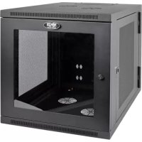
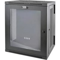
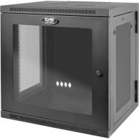
Low-Profile Wall-Mount SmartRack® Enclosures
Models: SRWF12U38, SRWF16U38
Table of Contents
- Important Safety Instructions 2
- Overview 2
- Feature Identification 2
- Preparation 3
4.1. Unpacking3
4.2. Disassembly3 - Installation 4
5.1. Mounting the Backplate 4
5.2. Unit and Equipment Installation 5
- Enclosure Configuration 7
6.1. Cable Access and Management 7
6.2. Ground Connection 7
- Specifications 7
- Storage and Service 7
- Warranty and Product Registration 8
Español 9
Français 17
Русский 25
PROTECT YOUR INVESTMENT!
Register your product for quicker service and ultimate peace of mind.
You could also win an ISOBAR6ULTRA surge protector—a \$100 value!
www.tripplite.com/warranty


1111 W. 35th Street, Chicago, IL 60609 USA • www.tripplite.com/support
Copyright © 2016 Tripp Lite. All rights reserved.
1. Important Safety Instructions
SAVE THESE INSTRUCTIONS
This Manual contains instructions and warnings that must be followed during the installation and operation of the product described in this manual. Failure to comply may invalidate the warranty and cause property damage or personal injury.
- Keep the enclosure in a controlled indoor environment, away from moisture, temperature extremes, flammable liquids and gasses, conductive contaminants, dust and direct sunlight.
- Leave adequate space at the front and rear of the enclosure for proper ventilation. Do not block, cover or insert objects into the external ventilation openings of the enclosure.
- The enclosure is extremely heavy. Use caution when handling the enclosure. Do not attempt to unpack, move or install it unassisted. Use a mechanical device such as a forklift or pallet jack to move the enclosure in the shipping container.
- Do not place any object on the enclosure, especially containers of liquid, and do not attempt to stack the enclosures.
- Inspect the shipping container and the enclosure for shipping damage. Do not use the enclosure if it is damaged.
- Leave the enclosure in the shipping container until it has been moved as close to the final installation location as possible.
• Install the enclosure in a structurally sound area capable of handling the load, or on a level floor that is able to bear the weight of the enclosure, all equipment that will be installed in the enclosure and any other enclosures and/or equipment that will be installed nearby. - Use caution when cutting packing materials. The enclosure could be scratched, causing damage not covered by the warranty.
- Save all packing materials for later use. Repacking and shipping the enclosure without the original packing materials may cause product damage that will void the warranty.
- Use of this equipment in life support applications where failure of this equipment can reasonably be expected to cause the failure of the life support equipment or to significantly affect its safety or effectiveness is not recommended. Do not use this equipment in the presence of a flammable anesthetic mixture with air, oxygen or nitrous oxide.
2. Overview
Low-Profile Wall-Mount SmartRack Enclosures provide convenient and secure vertical mounting for standard 19-inch rackmount equipment, regardless of vendor, and ship fully assembled for quick and easy deployment in areas previously considered impossible for placement. Using a modular design that easily assembles and disassembles, the enclosures support 8U (SRWF12U38) or 12U (SRWF16U38) of vertically mounted equipment up to 38 inches deep and 4U of patch panels. Both units support up to 400 lb. maximum weight.
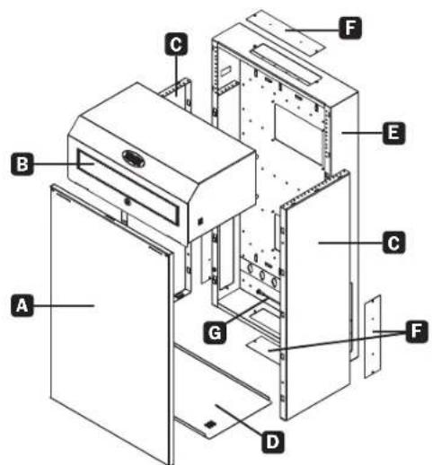
3 Feature Identification
A Front Panel
B Top Cover with Lock
C Side Panels
D Vent Tray
E 2U Backplate
F Cable Access Plates
G Ground Wire
Model SRWF12U38 shown. Product dimensions will vary by model.
4 Preparation
Caution! Read All Instructions and Warnings Before Installation!
Warning: Rack enclosures can be extremely heavy. Do not attempt to unpack, move or install the enclosure without assistance. Use extreme caution when handling the enclosure. Be sure to follow all handling and installation instructions. Do not attempt to install equipment without first stabilizing the enclosure.
4.1. Unpacking
Use at least two people to unpack the enclosure.
1 Move shipping box to a firm, level surface.
2 Open box and remove the corner protectors. Save all packing materials for later use unless certain they will not be required. Packing materials are recyclable.
3 With one person on each side, carefully lift the enclosure out of the box and place on a firm, level surface.
4 Examine the enclosure for any damage or loose parts. Confirm all parts are present. If anything is missing or damaged, contact Tripp Lite for assistance. Do not attempt to use the enclosure if it has been damaged.
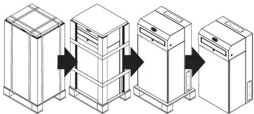
4.2. Disassembly
1 Remove Unit from Shipping Pallet and Packaging
flowchart
graph LR
    A["Step 1: Tower with Box"] --> B["Step 2: Tower with Box"]
    B --> C["Step 3: Tower with Box"]
    C --> D["Step 4: Tower with Box"]
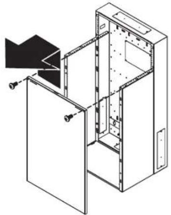
2 Unlock and remove Cover
natural_image
Isometric line drawing of a kitchen appliance with a door and cabinet (no text or symbols)3 Remove (2) #6-32 Locking Screws, then lift and remove Front Panel
natural_image
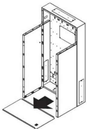
Technical line drawing of a cabinet or enclosure with internal components and mounting holes (no text or symbols)4 Remove Vent Tray
natural_image
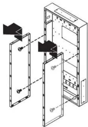
Isometric line drawing of a mechanical or architectural component with no visible text, numbers, or symbols.5 Remove (4) Screws, lift and remove Side Panels
natural_image
Technical line drawing of a server rack cabinet with mounting holes and internal components (no text or labels)5. Installation

The enclosure installation area must be able to withstand the weight of the enclosure and all mounted equipment. Refer to the Specifications section for enclosure model weight and capacity.
5.1. Mounting the Backplate
Mounting the Backplate to a Wall
Note: If the installation requires running cables through a wall, first remove one or both of the cable access panels prior to mounting the Backplate.
For Stud Mount
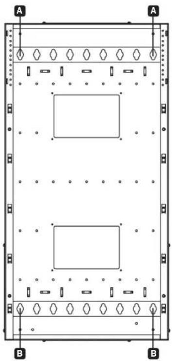
Locate solid studs, 16" on center, before marking top two locations for pilot holes. Drill #22 (0.157" or 4 mm) pilot holes, then drive two (2) M10, 5/16" or 3/8 x 2.0" long (minimum) bolts (not included) into the Backplate slots, spaced nominally at 16" at the top. Tighten the first two bolts A, and then drill holes for the remaining two (2) M10, 5/16" or 3/8" bolts into the bottom corners of the backplate B. Use a minimum of four (4) locations for full payload rating of 400 lb.
For Other Surfaces
When installing to other surfaces, drive toggle bolts into a 3/4" plywood-backed wall or fender washers and concrete tapping screws (3/16" x 2-1/4" minimum) into cinder block.
WARNING
- When installing wall mounts onto a concrete masonry unit (also known as a CMU or "cinder block"), verify that the actual concrete thickness is at least 35 mm (1 3/8") in order to hold the concrete anchors. DO NOT DRILL INTO MORTAR JOINTS! Be sure to mount Backplate onto solid sections of the blocks. The solid sections can generally be found 25 mm (1") toward the middle of the block from either end. An electric drill on a slow setting is suggested to drill the hole rather than a hammer drill, so as to avoid breaking out the back of the hole when entering a hollow section.
• Installers must verify that the supporting surface will safely support the combined load of the equipment and all attached hardware and components.
2-Post Rack-Mount Installation
The SRWF12U38 and SRWF16U38 are also designed for 2-post rack mounting. To attach, drive #12-24 screws (not included) through the Backplate into the corresponding 2-post mounting holes. Use a minimum of 10 locations for full payload rating of 400 lb.
natural_image
Technical diagram of a rectangular frame with two internal rectangular cutouts and labeled corners A and B (no text or symbols beyond labels)
natural_image
Technical line drawing of a multi-tiered electrical enclosure with multiple screw heads and mounting base (no text or symbols)5. Installation
5.2. Unit and Equipment Installation
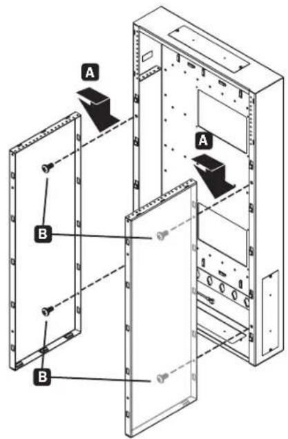
1 Side Panel Installation
After ensuring the Backplate is securely fastened to the wall or 2-post rack, install the Side Panels by inserting the Side Panel hooks into the rectangular cutouts in the Backplate. Apply downward pressure to properly seat the panels A.
Notes: The smooth surface of the Side Panels should face away from one another.
All Side Panel hooks must be engaged for proper assembly.
After the Side Panels are seated, the top surface will be flush with the internal 2U flanges in the Backplate. The bottom of the Side Panels will be flush with the Backplate bottom. Two holes for each Side Panel will align. Use four (4) supplied #12-24 screws for the two holes located in each Side Panel B. Ensure all screws are firmly secured to the Backplate.
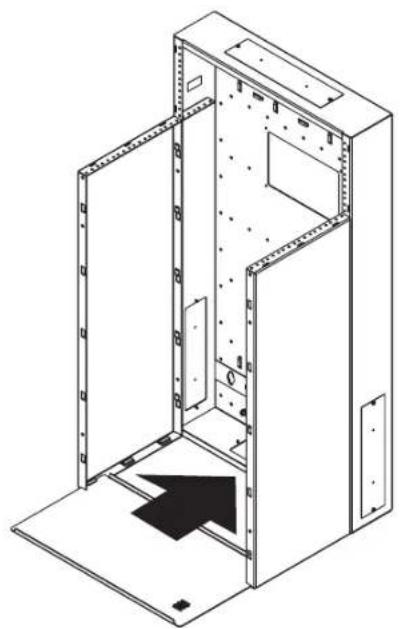
2 Vent Tray Installation
Slide the Vent Tray into the side panels' bottom slots. The right-angle flanges of the Vent Tray should face upward toward the cabinet's interior.
natural_image
Isometric line drawing of an open industrial cabinet with internal components and a black arrow indicating direction (no text or symbols)5. Installation
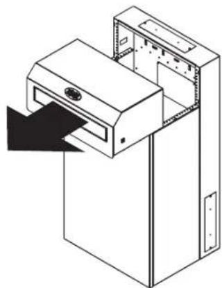
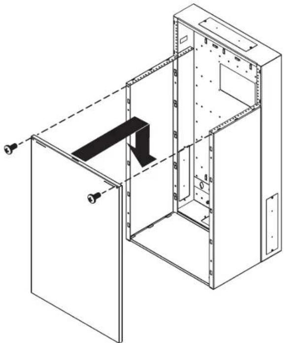
3 Front Panel Installation
Insert the Front Panel hooks into the rectangular cutouts in the Side Panels. All hooks must be engaged for proper assembly. Apply downward pressure to properly seat the panel. Secure the Front Panel using (2) #6-32 Locking Screws.

Before installing the first piece of equipment, make sure to temporarily install the Front Panel. This allows uniform spacing of the Side Panels, squares and aligns the cabinet, and ensures proper seating of the locking cover. After the first piece of equipment is securely installed, the Front Panel and Vent Tray can once again be removed to install any remaining equipment.
natural_image
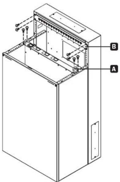
Technical line drawing of an open industrial cabinet with internal components and a black arrow indicating a directional flow (no text or symbols present)4 Equipment Installation
With user-supplied standard rack hardware (#12-24 screws), vertically mount up to 8U (SRWF12U38) or 12U (SRWF16U38) of network equipment A, and up to 4U of patch panels horizontally B.
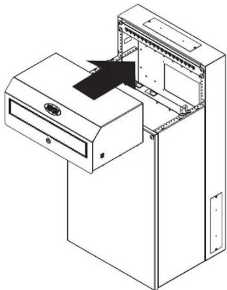
5 Cover Installation
Place cover onto the Side Panels and slide toward the Backplate. When properly seated, the cover should be flush against the Backplate and level with the top of the Backplate. The cover may then be locked with either of the two (2) keys provided.
natural_image
Isometric line drawing of an open electrical cabinet with a black arrow indicating a component (no text or symbols present)6. Enclosure Configuration
6.1. Cable Access and Management
The top, bottom and sides of the cabinet contain rectangular openings (four total) for cable access and management. These can be opened or closed by unscrewing or screwing the removable cable access panel.
For improved cooling efficiency and a cleaner installation appearance, all cable access holes are compatible with Tripp Lite's SRBRUSHWM Brush Strip Plate accessory. The brush strip plate securely fits into the cable routing panel to block unwanted airflow. For more information, visit www.tripplite.com.
6.2. Ground Connection
All parts of the enclosure are grounded to the frame. Use the enclosure's front or rear threaded grounding point and an M6 screw to connect the frame directly to your facility's earth ground connection with an 8 AWG (3.264 mm) wire. Warning: Attach each enclosure to earth ground separately. Do not use the enclosure without an earth ground connection.
7. Specifications
| Model SRWF12U38 SRWF16U38 | ||
| Total Rack Units 12U 16U | ||
| Patch Panel Rack Units 4U 4U | ||
| Equipment Rack Units 8U 12U | ||
| Backplate Depth 4.65 in. / 118 mm | 4.65 in. / 118 mm | |
| Unit Dimensions (H x W x D) 38 x 19.7 x 16 in. / 965 x 500 x 408 mm | 38 x 19.7 x 23.1 in. / 965 x 500 x 587 mm | |
| Unit Weight 66 lb. / 30 kg 81.5 lb. | / 37 kg |
8. Storage and Service
Storage
The enclosure should be stored in a controlled indoor environment, away from moisture, temperature extremes, flammable liquids and gasses, conductive contaminants, dust and direct sunlight. Store the enclosure in its original shipping container if possible.
Service
Your Tripp Lite product is covered by the warranty described in this manual. A variety of Extended Warranty and On-Site Service Programs are also available from Tripp Lite. For more information on service, visit www.triplite.com/support. Before returning your product for service, follow these steps:
- Review the installation and operation procedures in this manual to insure that the service problem does not originate from a misreading of the instructions.
- If the problem continues, do not contact or return the product to the dealer. Instead, visit www.triplite.com/support.
- If the problem requires service, visit www.triplite.com/support and click the Product Returns link. From here you can request a Returned Material Authorization (RMA) number, which is required for service. This simple on-line form will ask for your unit's model and serial numbers, along with other general purchaser information. The RMA number, along with shipping instructions will be emailed to you. Any damages (direct, indirect, special or consequential) to the product incurred during shipment to Tripp Lite or an authorized Tripp Lite service center is not covered under warranty. Products shipped to Tripp Lite or an authorized Tripp Lite service center must have transportation charges prepaid. Mark the RMA number on the outside of the package. If the product is within its warranty period, enclose a copy of your sales receipt. Return the product for service using an insured carrier to the address given to you when you request the RMA.
9. Warranty and Product Registration
5-Year Limited Warranty
Seller warrants this product, if used in accordance with all applicable instructions, to be free from original defects in material and workmanship for a period of 5 years from the date of initial purchase. If the product should prove defective in material or workmanship within that period, Seller will repair or replace the product, at its sole discretion.
THIS WARRANTY DOES NOT APPLY TO NORMAL WEAR OR TO DAMAGE RESULTING FROM ACCIDENT, MISUSE, ABUSE OR NEGLECT. SELLER MAKES NO EXPRESS WARRANTIES OTHER THAN THE WARRANTY EXPRESSLY SET FORTH HEREIN. EXCEPT TO THE EXTENT PROHIBITED BY APPLICABLE LAW, ALL IMPLIED WARRANTIES, INCLUDING ALL WARRANTIES OF MERCHANTABILITY OR FITNESS, ARE LIMITED IN DURATION TO THE WARRANTY PERIOD SET FORTH ABOVE; AND THIS WARRANTY EXPRESSLY EXCLUDES ALL INCIDENTAL AND CONSEQUENTIAL DAMAGES. (Some states do not allow limitations on how long an implied warranty lasts, and some states do not allow the exclusion or limitation of incidental or consequential damages, so the above limitations or exclusions may not apply to you. This warranty gives you specific legal rights, and you may have other rights which vary from jurisdiction to jurisdiction).
WARNING: The individual user should take care to determine prior to use whether this device is suitable, adequate or safe for the use intended. Since individual applications are subject to great variation, the manufacturer makes no representation or warranty as to the suitability or fitness of these devices for any specific application.
Product Registration
Visit www.triplite.com/warranty today to register your new Tripp Lite product.You'll be automatically entered into a drawing for a chance to win a FREE Tripp Lite product!*
* No purchase necessary. Void where prohibited. Some restrictions apply. See website for details.
Regulatory Compliance Identification Numbers
For the purpose of regulatory compliance certifications and identification, your Tripp Lite product has been assigned a unique series number. The series number can be found on the product nameplate label, along with all required approval markings and information. When requesting compliance information for this product, always refer to the series number. The series number should not be confused with the marketing name or model number of the product.
Tripp Lite has a policy of continuous improvement. Specifications are subject to change without notice.


1111 W. 35th Street, Chicago, IL 60609 USA • www.tripplite.com/support
4 Preparación
flowchart
graph LR
    A["Initial Storage Unit"] --> B["Intermediate Storage Unit"]
    B --> C["Final Storage Unit"]
natural_image
Isometric line drawing of a multi-chamber air purifier unit with a black arrow indicating airflow direction (no text or symbols)natural_image
Technical line drawing of a door frame assembly with mounting holes and internal components (no text or symbols)natural_image
Isometric line drawing of a cabinet interior with an open door and a black arrow indicating a component (no text or symbols)natural_image
Technical line drawing of a server rack cabinet with mounting holes and internal compartments (no text or labels)5. Instalación

natural_image
Pure technical diagram of a rectangular enclosure with mounting holes and internal compartments, no text or symbols present.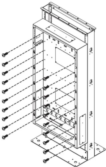
natural_image
Technical line drawing of an electrical enclosure with multiple screw holes and mounting base (no text or symbols)5. Instalación
natural_image
Isometric line drawing of a server rack cabinet with mounting flanges and internal compartments (no text or symbols)5. Instalación
natural_image
Technical line drawing of an open industrial cabinet with internal components and a black arrow indicating a directional flow (no text or symbols present)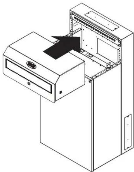
natural_image
Isometric line drawing of a cabinet with an open door and internal components, no text or symbols present1111 W. 35th Street, Chicago, IL 60609 USA • www.tripplite.com/support
4 Préparation
flowchart
graph LR
    A["Initial Setup"] --> B["Assembly"]
    B --> C["Intermediate Setup"]
    C --> D["Final Assembly"]
natural_image
Isometric line drawing of a cabinet with an open lid and internal components (no text or symbols)natural_image
Technical line drawing of a door frame with internal compartments and mounting fixtures (no text or symbols)natural_image
Isometric line drawing of a cabinet or enclosure with an open door and internal components, showing no text or symbols.natural_image
Technical line drawing of a server rack cabinet with mounting holes and internal compartments (no text or labels)5. Installation

natural_image
Technical diagram of a server rack frame with labeled points A and B, showing no text or symbols beyond labels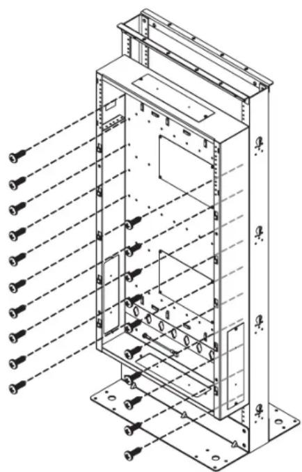
natural_image
Technical line drawing of an electrical enclosure with multiple screw holes and mounting base (no text or symbols)5. Installation
natural_image
Isometric line drawing of an open industrial cabinet with internal components and a black arrow indicating a directional flow (no text or symbols)5. Installation
natural_image
Technical line drawing of an open industrial cabinet with a black arrow indicating a component or connection (no text or symbols present)natural_image
Isometric line drawing of a server rack unit with open door and internal panel (no text or symbols)
1111 W. 35th Street, Chicago, IL 60609 USA • www.tripplite.com/support
1111 W. 35th Street, Chicago, IL 60609 USA • www.tripplite.com/support
4. Подготовка
natural_image
Isometric line drawing of a kitchen appliance with a door handle and ventilation unit (no text or symbols)natural_image
Technical line drawing of a door frame with internal components and mounting points (no text or symbols)natural_image
Isometric line drawing of a cabinet interior with open doors and a black arrow indicating a component (no text or symbols)5. Установка

natural_image
Technical diagram of a server rack frame with labeled points A and B, showing no text or symbols beyond labels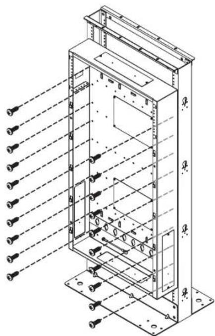
natural_image
Technical line drawing of a multi-tiered electrical enclosure with multiple screw holes and mounting base (no text or labels)5.Установка
natural_image
Isometric line drawing of an open industrial control cabinet with internal components and a black arrow indicating a component (no text or symbols)5. Установка
natural_image
Technical line drawing of an open industrial cabinet with a black arrow indicating a component or connection (no text or symbols present)5 Установка крышки
natural_image
Isometric line drawing of a mechanical device with a central component and mounting bracket (no text or symbols)
1111 W. 35th Street, Chicago, IL 60609 USA - www.tripplite.com/support