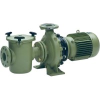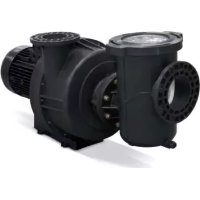
KIVU - Pump ASTRALPOOL - Free user manual and instructions
Find the device manual for free KIVU ASTRALPOOL in PDF.


User questions about KIVU ASTRALPOOL
0 question about this device. Answer the ones you know or ask your own.
Ask a new question about this device
Download the instructions for your Pump in PDF format for free! Find your manual KIVU - ASTRALPOOL and take your electronic device back in hand. On this page are published all the documents necessary for the use of your device. KIVU by ASTRALPOOL.
USER MANUAL KIVU ASTRALPOOL
CENTRIFUGAL PUMP FOR SWIMMING POOLS
POMPES CENTRIFUGE POUR PISCINES
BOMBAS CENTRÍFUGAS PARA PISCINAS
POMPE CENTRIFUGHE PER PISCINE
ZENTRIFUGALPUMPEN FÜR SCHWIMMBECKEN
BOMBAS CENTRÍFUGAS PARA PISCINAS
CE
ASTRALPOOL

KIVU
English - POOL PUMPS
KIVU MANUAL....3
Français - POMPES POUR PISCINES
MANUEL KIVU 13
Español - BOMBAS PARA PISCINAS
MANUAL KIVU 23
Italiano - POMPA PER PISCINAS
MANUALE KIVU 33
Deutsch - PUMPEN FÜR SCHWIMMBECKEN
KIVU MANUELL 43
Português - BOMBAS PARA PISCINAS
MANUAL KIVU 53
IMPORTANT
This manual contains basic information on the safety measures to be adopted during installation and start-up. The fitter and the user must therefore read the instructions before installation and start-up.
1. GENERAL SAFETY INSTRUCTIONS
These symbols ( △ indicate the possibility of danger where the corresponding instructions are not followed.
DANGER. Risk of electrocution.
Failure to abide by these instructions may lead to the risk of electrocution.

DANGER.
Failure to abide by these instructions may lead to the risk of injury or damage.

WARNING.
Failure to abide by these instructions may lead to the risk of damage to the pump or the installation.
2. GENERAL SAFETY REGULATIONS
GENERAL

- The machines indicated in this Manual are especially designed for the pre-filtering and recirculation of water in swimming pools.

- They are designed to work with clean water at temperatures not exceeding 35^ . (Fig. 4 T med. Max).
- Install them in line with the specific instructions for each installation.
- Respect current regulations regarding accident prevention.
- All modifications to the pump require prior authorisation from the manufacturer. Original spare parts and accessories authorised by the manufacturer ensure greater safety. The pump manufacturer is exempt from all liability regarding any damage caused by unauthorised spare parts or accessories.

- When working on each machine or on the units linked to them, disconnect the unit from the power supply and the start-up devices, as the electrical parts of the pump are live during operation.

- All assembly and maintenance work must be carried out by qualified and authorised personnel who have carefully read the installation and service instructions.
- To guarantee safety when operating the machine, you must comply with that set out in the installation and service instructions.
- In the event of defective operation or faults, contact your supplier or nearest representative.
WARNINGS DURING INSTALLATION AND ASSEMBLY WORK

- Once the pump has been removed from the box, it should be handled by the suction inlet and the engine body, and should not be held up in just one point.

- When connecting the electrical wiring to the machine motor, check the layout inside the connection box and make sure there are no pieces of wiring inside after it has been closed and that the earthing conductor is correctly connected. Connect the motor in line with the wiring diagram attached to the machine.
- Make sure that the electrical wiring connections to the machine terminal box are well mounted and screwed tight to the connection terminals.
- The equipment should be connected to an alternating current supply (see data on the pump's plate) with earth connection, protected by a residual current device (RCD) having a rated residual operating current not exceeding 30 mA.
-
Correctly use the seal of the terminal box for the electrical motor to prevent water getting in. Likewise, position and tighten the gland inside the cable duct of the terminal box.
-
Make sure that water is unable to enter the motor or the live electrical parts.
- Where the intended use is not as indicated, additional technical adaptations and regulations may be required.

WARNINGS DURING START-UP

Before starting the machine, check the calibration of the electric protection devices on the motor and that the protection against electrical and mechanical contacts is correctly positioned and secure.
NOTE
The pool should not be used while the pumping equipment is running.
Do not use the pump if anyone is in contact with the water.
WARNINGS DURING ASSEMBLY AND MAINTENANCE WORK

- Take into account national installation regulations when assembling and installing the pumps.
- Make sure that water is unable to enter the motor or the live electrical parts.
- Avoid contact at all times - even accidentally - with moving machine parts while the machine is running and/or before it comes to a complete standstill.
- Wait for the machine to come to a halt before handling it.
- Before any electrical or mechanical maintenance operation, disconnect the unit from the power supply and block the start-up devices.
- Follow the steps below before handling the machine:
- Disconnect the machine from the mains.
- Block all start-up devices.
- Check that there is no voltage in the circuits, even in the auxiliary circuits and additional services.
- Wait for the impeller to come to a complete standstill.


The list indicated must be used as a guideline and is not binding for safety purposes. There may be particular safety regulations in specific standards.

Due to the complex nature of the cases treated, the installation, user and maintenance instructions contained in this manual do not seek to examine all possible and imaginable cases of service and maintenance. Should you require additional instruction or have specific problems, please do not hesitate to contact the nearest Technical Assistance Service.
The electrical installation should be done by someone qualified in working with electrical equipment. This equipment is not designed for those with physical, sensory or mental handicap or people lacking in experience, unless done under supervision or with instructions of use from a person in charge of safety.
Do not permit children nor adults to sit or lean on the equipment. Children should be supervised to ensure that they do not play with the equipment.
3. HANDLING THE PUMP
HANDLING
Weight: See the label on the packaging.

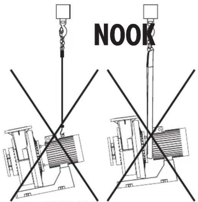
Note: The motors are supplied with eye bolts that should not be used to lift the entire pump assembly. See fig. 1
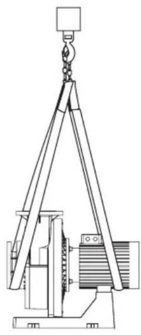
The pumps can only be lifted using nylon straps attached to a hook as shown in fig. 3.
text_image
NOOKFIG. 1 FIG. 2 FIG. 3
Lifting the pump incorrectly
natural_image
Line drawing of a crane lifting a motor (no text or symbols)Lifting the pump correctly
4. INFORMATION ON THE IDENTIFICATION LABEL
Each pump has two identification labels that provide information about it. Both labels are placed on the motor (one on the cover of the terminal box and another on the fan cover).
It provides information on the hydraulic characteristics of the pump. (Fig. 4)
ASTRALPOOL
Manufactured by : Metalast, S.A.U. Pg.de Sanllehy, 25 - 08213 Polinyà

| REF: | N°SERIE: 000000 | ||
| Q | m3/h | H | m.w.h. |
| V | V~ | I | A~ |
| P1 | kW | P2 | kW |
| n | r.p.m. | Hz | |
| H max | m.w.h. | Tmed.max = °C | |
| H min | m.w.h. | Date : CE | |
| Made in | |||
| Ref. Pump code | |
| Serial no. Serial number of the pump | |
| Q Nominal flow rate (m ^3 /h) | |
| H Nominal differential pressure (m.w.h.) | |
| V Supply voltage | |
| I Nominal operating intensity | |
| P1 Absorbed power | |
| P2 Delivered power | |
| n Pump speed | |
| Hz Nominal frequency | |
| Hmax Closing differential pressure (m.w.h.) | |
| Hmin Minimum operating differential pressure | |
| Date Date of manufacture | |
| Made in Country of manufacture | |
LABEL LOCATED ON THE FAN COVER
It provides information of the motor. (Fig. 5).
| SERIAL NO: TYPE: | COS Φ |  | |||||
| Ins. Cl. IP-XX | |||||||
| V Hz P1 | -kW | P2-kW R | PM A | ||||
| Serial no. Motor code | |
| Type Type of motor | |
| Cos Φ | Power factor |
| V Motor supply voltage | |
| Hz Frequency | |
| P1 Motor power supply | |
| P2 Motor mechanical power | |
| A Intensity | |
| IP-XX Protection | |
| Ins. Cl. Insulation class | |
| IE3 Motor efficiency | |
| RPM Revolutions per minute | |
5. LOCATION

Warning: Do not install the pump in enclosed or poorly ventilated environments where conditions may be unfavourable for the presence of staff. Ensure that there is enough light on the pump for the installer.

- Fit the pump underneath the water level in the pool to improve pump performance.
- Where a self-priming pump is to be fitted above the water level, the pressure differential to the pump suction should not be higher than 0.02 MPa (2 mH2O), ensuring that the suction pipe is as short as possible as a longer pipe would increase suction time and the installation's load losses.
- Self-priming Kivu pumps are 3cv,4cv and 5.5cv models with prefilter.
- Make sure that the pump is safe from possible flooding and receives dry ventilation.

6. INSTALLATION AND ASSEMBLY

- Our pumps may only be assembled and installed in pools or ponds that are compliant with HD 384.7.702. Should you have any doubts, please consult your specialist.

- Fit the pump horizontally due to the pre-filter. The pumps are fitted with a pre-filter with a basket inside to collect any large particles, as they may damage the hydraulic part inside the pump.
- All pumps are fitted with a foot with holes in it to anchor it to the ground.
INSTALLATION
- The pumps should be installed horizontally.
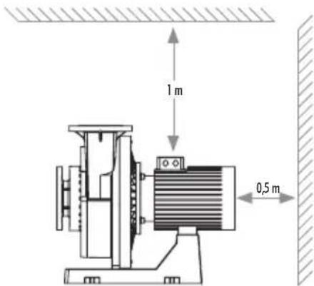
- The pumps need a free space of 0.5 m behind the motor and at least 1 m above the motor so that lifting equipment can be used.
text_image
1 m 0,5 mFIG. 6: Free space required
INSTALLING PIPES (RECOMMENDATIONS)
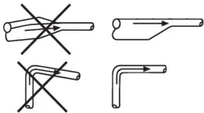
When installing the pipes, ensure that the pump body is not under pressure from the pipes.
The suction and discharge pipes should be of the correct size, taking into account the inlet pressure of the pump.
Install the pipes so that air pockets are avoided, especially on the suction end of the pump.
natural_image
Four technical line drawings showing different pipe connection configurations with no text or symbolsFIG. 7: Pipes
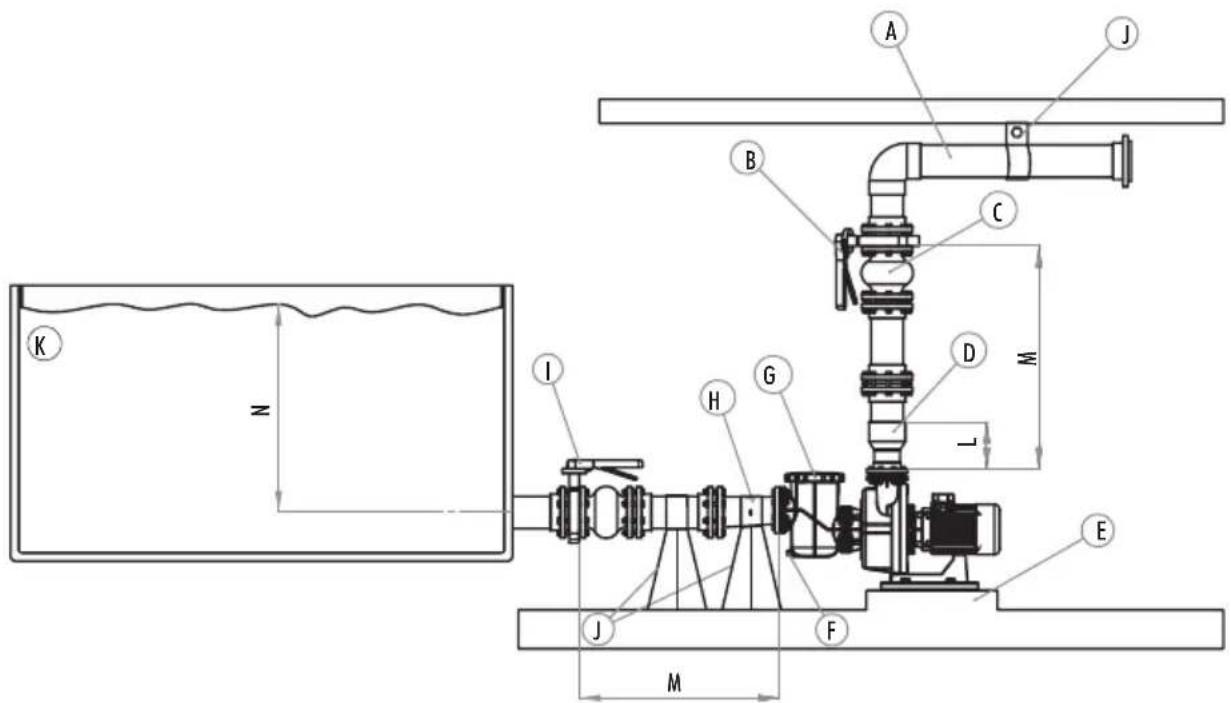
Assemble the shut-off valves on both sides of the pump to prevent the system from emptying if we have to clean or repair the pump.
Check that the pipes are held in place as close as possible to the pump, both on the suction and the discharge sides. The counter flanges should be aligned with respect to the pump flanges, without stresses that could cause damage to it.

The pump cannot operate when a valve is closed, as this will cause an increase in the temperature/formation of steam in the pump, which may cause it damage.
text_image
K z I H G B A J C D M L E J F MFIG. 8: Installing the pump
| ENGLISH FRANÇAIS ESPAÑOL ITALIANO DEUTSCH PORTUGUÊS | ||||||
| A | Return pipework | Refoulement | Tubería impulsión | Tubazione di mandata | Druckverrohrung | Tubagem de impulsão |
| B | Conikol valve | Vanne de contróle | Válvula de control | Valvola de controllo | Kontrollventil | Válvula de controle |
| C | Expansion joint | Joint de dilatation | Junta de expansión | Giunto di espansione | Rohrkompensatoren | Junta de compensação |
| D | Coincentric cone | Cone concentrique | Cono concéntrico | Cono di Giunzione | Konzentrischer konus | Cone concentrico |
| E | Concrete foundation | Fondation en béton | Cimentación de hormigón | Base in calcestruzzo Betonfundament | Maciço de betão | |
| F | Drain plug | Bouchon de purge | Tapón de purga | Tappo di scarico | Entleerungsstopfen | Tampão de despejo |
| G | Prefilter Lid | Couvercle prefiltre | Tapa prefiltro | Coperchio prefiltro | Vorfilterdeckel | Tampa do prefiltro |
| H | Eccentric cone | Cóne excentrique | Cono excentrico | Cono excentrico | Exzentrischer konus | Cone excentrico |
| I | Stop valve | Vanne D'arret | Válvula de parada | Valvola de chiusura | Absperrventil | Válvula de retenção |
| J | Supports | Supports | Soportes | Supporti | Stützen | Suportes |
| K | Tank | Bac | Depósito | Deposito | Behälter | Deposito |
| L | 2 times the pipe diameter | 2 fois le diametre du tube | 2 veces el diámetro de tubo | 2 volte il diametrico del tubo | 2 x Rohrdurchmesser | 2 vezes o diámetro do tubo |
| M | 10 times the pipe diameter | 10 fois le diametre du tube | 10 veces el diámetro de tubo | 10 volte il diametrico del tubo | 10 x Rohrdurchmesser | 10 vezes o diámetro do tubo |
| N | Minimum distance | Distance minimale | Distancia mínima | Distanza mínima | Mindestabstand | Distância mínima |
ELIMINATING NOISE AND VIBRATIONS
For optimum operation and to reduce noise and vibrations to a minimum, we advise the use of vibration absorbers.
Noise and vibrations are generated by the revolutions of the pump motor and by the flow in pipes and connectors. Their effect on the environment is subjective and depends on the correct installation and condition of the other parts of the system.
The best way of eliminating noise and vibrations is to use a concrete foundation, vibration absorbers and expansion joints.
7. ELECTRICAL INSTALLATION

- It is essential that you use a multiple disconnection device with a space of at least 3 mm between surfaces to disconnect the equipment from the electrical current.
- Use a rigid cable to connect to the mains. If you use a flexible cable to connect to the mains, it must have cable lugs to connect to the terminals of the pump motor.
- The equipment should be connected to an alternating current supply (see data on the pump's plate) with earth connection, protected by a residual current device (RCD) having a rated residual operating current not exceeding 30 mA.
- Adjust the value of the thermal relay appropriately depending on the pump current.
- Before connecting the motor, check the type of fuse required.
- Check the correct layout and connection of the earthing cable in the equipment.
- Respect the electrical installation and connection conditions. Failure to do so may lead to the pump manufacturer declining all responsibility and rendering the guarantee null and void.
- Special regulations may exist for the installation.
- Unsuitable mains connections involve the risk of electrocution.
For pumps with a three-phase motor:
- Use a motor guard with magneto-thermal protection.
-
Protect the pump against overloads with a cut-off switch for the motor.
-
Adjust the thermal value according to the thermal protection table. For the connection (3 x 230 V network), use the protection with the highest indicated value. For the connection Y (3 x 400 V network), use the protection with the lowest indicated value.
- Connect the lowest voltage at and the highest at Y for voltage intervals other than 230/400 V; 400/690 V.
- For AC, use a H07 RN-F3 type connection sleeve with a cable section that adapts to the power of the motor and the length of the cable.
- The mains cable may only be connected by skilled, authorised personnel.
• These pumps are suitable for use with a variable frequency drive.
- It is recommended that you work within the limits of 20Hz to 50Hz.
- For more information, contact the supplier of the variable frequency drive.
8. START-UP INSTRUCTIONS
PRIOR TO START-UP

- Carry out the following operations before starting the pump:
- Remove the pre-filter cap by unscrewing the nut holding it in place.
- Fill the pump with water through the pre-filter until it rises up through the suction pipe.
- Should the basket be removed during these operations, do not forget to replace it to prevent large particles from entering the pump that could block it.
- Fit the pre-filter cap and screw on tight, not forgetting to fit the seal in its housing.
- Check that the mains voltage and frequency correspond with those indicated on the pump characteristics plate.
- The pumps must not be run without the pre-filter having first been filled with water. Where this is not the case, the mechanical gasket may be damaged, leading to a loss of water.

- Check that the motor rotates in the correct direction by means of the fan located at the back of the motor that can be seen through the view hole on the fan cover.
START-UP

- Open all the valves and connect the motor.
- Activate the self-priming and wait a reasonable time for this to be completed.
- The PUMP MUST NEVER FUNCTION WHEN IT IS DRY. The pump must not be started when it is dry as this would cause damage to its mechanical seal, causing water leaks.

- The pump cannot function against a closed valve as this will cause an increase in the temperature and formation of steam in the pump, which could cause it damage.

MINIMUM PRESSURE -NPSHr /CAVITATION
- The minimum suction pressure depends on the flow rate and power of the Kivu pump. See NPSHr graphs.
- If the pump does not have the minimum pressure required, it can cavitate. Steam would cause vibrations that would damage the moving parts of the pump (impeller, mechanical seal, bearings) and fixed parts (flange, diffuser, volute).
- To avoid the effect of cavitation in the pump, ensure that the minimum pressure at the inlet of the pump is that required in the NPSHr graph.
MAXIMUM FLOW RATE
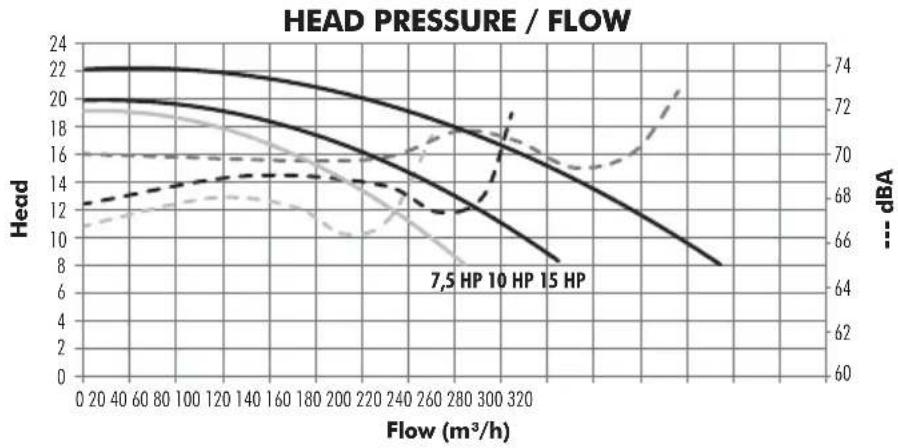
- The maximum flow rate is determined by the minimum differential pressure of the pump. The minimum pressure should never be less than that indicated on the pump label. (Fig.4)
MINIMUM FLOW RATE
- The pump should not work against a closed discharge valve, as this would cause an increase in temperature which could damage parts of the pump and shorten its useful life.
- The continuous minimum flow rate must be at least 10% of the nominal flow rate indicated on the pump label. (Fig.4).
9. MAINTENANCE
- For regular control:
- Check that the mechanical parts are tightly secured and check the condition of the screws supporting the machine.
- Clean the pre-filter basket regularly to avoid drops in pressure. To prevent the basket from breaking, do not hit it during the cleaning process.
- The pump should be checked every 100 hours of operation or less, depending on the level of cleanliness of the water.
- Check the temperature of the machine and the electric motor. In the event of a fault, stop the machine immediately and contact the nearest Technical Assistance Service.
- Check for machine vibrations. In the event of a fault, stop the machine immediately and contact the nearest Technical Assistance Service.
- Should the pump stop, check that consumption of the running motor in amperes is equal to or below that indicated on the manufacturer's characteristics plate. If this information is available, contact the nearest Technical Assistance Service.
- Empty the pump if it is to remain at a standstill for a certain length of time, especially in cold countries where there is a risk of freezing.
- Remove the purge cap to empty the pump.
- Every time the pre-filter is opened, clean the seal and its seating of any impurities to ensure airtightness when the cap is closed.
- Pump components that, due to their normal use, suffer wear and/or tear must be regularly replaced to ensure good pump performance. The following table shows the perishables and/or consumables used in the pump and their estimated working life.
| COMPONENT DESCRIPTION ESTIMATED | WORKING LIFE |
| 0 rings and general seals 1 year | |
| Mechanical seal 1 year | |
| Bearings 1 year |
The estimated working life of the parts above has been established according to normal product use and installation conditions. Follow the instructions in the installation manual to maintain the working life of the pump.
10. REMOVAL
- The motor unit can be removed from the pump body without having to disconnect the pump's suction and return pipes.
- To remove the Motor unit from the pump body, remove the screws joining them together.
11. TROUBLESHOOTING
- The pump is not primed 4. The pump will not start
- The pump releases only a small flow of water 5. The motor is making a noise but will not start
- The pump makes a noise 6. The motor is stopped
| 1 2 3 4 | 5 6 | CAUSES | SOLUTIONS | |||
| ● | ● | Air entering the suction pipe Check the condition of connections and seals on the suction pipe | ||||
| ● | Filter cap badly sealed Clean the filter cap and check the condition of the rubber seal | |||||
| ● | ● | Inverted motor turning Invert 2 power phases | ||||
| ● | ● | ● | Wrong voltage | Check the voltage on the characteristics plate and that of the mains | ||
| ● | Pre-filter blocked Clean the filter | |||||
| ● | Load loss in the installation Prevent parts from causing load loss wherever possible | |||||
| ● | Pump incorrectly secured Secure the pump correctly | |||||
| ● | Motor blocked Remove the motor and contact the technical service | |||||
| Increased temperature in the terminal box due to electric arc | Check the terminal box connections | |||||
| The thermal protection trips Connect the cables correctly to the terminal boxes | ||||||
| Incorrect terminal box connections | Tighten the cable correctly to the terminal / Adapt the size of the cable connection to the terminal box | |||||
IMPORTANT
natural_image
Technical line drawing of a crane lifting a motor (no text or symbols)Levage correct de la pompe
4. INFORMATION DE L'ÉTIQUETTE D'IDENTIFICATION
natural_image
Four technical line drawings showing different pipe connection configurations with crosshair indicators (no text or symbols)FIG. 7: Tuyauteries
text_image
K N A J B C D M I H G J F E MFIG. 8: Installation de la pompe
| ENGLISH FRANÇAIS ESPAÑOL ITALIANO DEUTSCH PORTUGUÊS | ||||||
| A | Return pipework | Refoulement | Tubería impulsión | Tubazione di mandata | Druckverrohrung | Tubagem de impulsão |
| B | Conikol valve | Vanne de contrôle | Válvula de control | Valvola de controllo | Kontrollventil | Válvula de controle |
| C | Expansion joint | Joint de dilatation | Junta de expansión | Giunto di espansione | Rohrkompensatoren | Junta de compensação |
| D | Coincentric cone | Cone concentrique | Cono concéntrico | Cono di Giunzione | Konzentrischer konus | Cone concentrico |
| E | Concrete foundation | Fondation en béton | Cimentación de hormigón | Base in calcestruzzo Betonfundament | Maciço de betão | |
| F | Drain plug | Bouchon de purge | Tapón de purga | Tappo di scarico | Entleerungsstopfen | Tampão de despejo |
| G | Prefilter Lid | Couvercle prefiltre | Tapa prefiltro | Coperchio prefiltro | Vorfilterdeckel | Tampa do prefiltro |
| H | Eccentric cone | Cóne excentrique | Cono excentrico | Cono excentrico | Exzentrischer konus | Cone excentrico |
| I | Stop valve | Vanne D'arret | Válvula de parada | Valvola de chiusura | Absperrventil | Válvula de retenção |
| J | Supports | Supports | Soportes | Supporti | Stützen | Suportes |
| K | Tank | Bac | Depósito | Deposito | Behälter | Deposito |
| L | 2 times the pipe diameter | 2 fois le diametre du tube | 2 veces el diámetro de tubo | 2 volte il diametricodel tubo | 2 x Rohrdurchmesser | 2 vezes o diámetro do tubo |
| M | 10 times the pipe diameter | 10 fois le diametre du tube | 10 veces el diámetro de tubo | 10 volte il diametricodel tubo | 10 x Rohrdurchmesser | 10 vezes o diámetro do tubo |
| N | Minimum distance | Distance minimale | Distancia mínima | Distanza mínima | Mindestabstand | Distância mínima |
ÉLIMINATION DE BRUITS ET VIBRATIONS
natural_image
Technical line drawing of a crane lifting a motor (no text or symbols)natural_image
Four technical line drawings showing different pipe connection configurations with cross-bracing (no text or symbols)FIG. 7: Tuberías
text_image
K N A J B C D M L I H G E J F Mnatural_image
Line drawing of a crane lifting a motor (no text or symbols present)natural_image
Four technical line drawings showing different pipe connection configurations with crosshair indicators (no text or symbols)FIG. 7: Tubazioni
text_image
K z I H G D M L E J F M A B C JFIG. 8: Installation de la pompe
| ENGLISH FRANÇAIS ESPAÑOL ITALIANO DEUTSCH PORTUGUÊS | ||||||
| A | Return pipework | Refoulement | Tubería impulsión | Tubazione di mandata | Druckverrohrung | Tubagem de impulsão |
| B | Conikol valve | Vanne de contrôle | Válvula de control | Valvola de controllo | Kontrollventil | Válvula de controle |
| C | Expansion joint | Joint de dilatation | Junta de expansión | Giunto di espansione | Rohrkompensatoren | Junta de compensação |
| D | Coincentric cone | Cone concentrique | Cono concéntrico | Cono di Giunzione | Konzentrischer konus | Cone concentrico |
| E | Concrete foundation | Fondation en béton | Cimentación de hormigón | Base in calcestruzzo Betonfundament | Maciço de betão | |
| F | Drain plug | Bouchon de purge | Tapón de purga | Tappo di scarico | Entleerungsstopfen | Tampão de despejo |
| G | Prefilter Lid | Couvercle prefiltre | Tapa prefiltro | Coperchio prefiltro | Vorfilterdeckel | Tampa do prefiltro |
| H | Eccentric cone | Cóne excentrique | Cono excentrico | Cono excentrico | Exzentrischer konus | Cone excentrico |
| I | Stop valve | Vanne D'arret | Válvula de parada | Valvola de chiusura | Absperrventil | Válvula de retenção |
| J | Supports | Supports | Soportes | Supporti | Stützen | Suportes |
| K | Tank | Bac | Depósito | Deposito | Behälter | Deposito |
| L | 2 times the pipe diameter | 2 fois le diametre du tube | 2 veces el diámetro de tubo | 2 volte il diametrico del tubo | 2 x Rohrdurchmesser | 2 vezes o diámetro do tubo |
| M | 10 times the pipe diameter | 10 fois le diametre du tube | 10 veces el diámetro de tubo | 10 volte il diametrico del tubo | 10 x Rohrdurchmesser | 10 vezes o diámetro do tubo |
| N | Minimum distance | Distance minimale | Distancia mínima | Distanza mínima | Mindestabstand | Distância mínima |
natural_image
Technical line drawing of a crane lifting a motor (no text or symbols present)Manufactured by : Metalast, S.A.U.
Pg.de Sanllehy, 25 - 08213 Polinyà

| REF: | N°SERIE: 000000 | ||
| Q | m3/h | H | m.w.h. |
| V | V~ | I | A~ |
| P1 | kW | P2 | kW |
| n | r.p.m. | Hz | |
| H max | m.w.h. | Tmed. max = °C | |
| H min | m.w.h. | Date : CE | |
| Made in | |||
natural_image
Four technical line drawings showing different pipe connection configurations with cross marks (no text or symbols)text_image
K z I H G D M L E J F M A B C JAbb.8: Pumpeninstallation
| ENGLISH FRANÇAIS ESPAÑOL ITALIANO DEUTSCH PORTUGUÊS | ||||||
| A | Return pipework | Refoulement | Tubería impulsión | Tubazione di mandata | Druckverrohrung | Tubagem de impulsão |
| B | Conikol valve | Vanne de contróle | Válvula de control | Valvola de controllo | Kontrollventil | Válvula de controle |
| C | Expansion joint | Joint de dilatation | Junta de expansión | Giunto di espansione | Rohrkompensatoren | Junta de compensação |
| D | Coincentric cone | Cone concentrique | Cono concéntrico | Cono di Giunzione | Konzentrischer konus | Cone concentrico |
| E | Concrete foundation | Fondation en béton | Cimentación de hormigón | Base in calcestruzzo Betonfundament | Maciço de betão | |
| F | Drain plug | Bouchon de purge | Tapón de purga | Tappo di scarico | Entleerungsstopfen | Tampão de despejo |
| G | Prefilter Lid | Couvercle prefiltre | Tapa prefiltro | Coperchio prefiltro | Vorfilterdeckel | Tampa do prefiltro |
| H | Eccentric cone | Cóne excentrique | Cono excentrico | Cono excentrico | Exzentrischer konus | Cone excentrico |
| I | Stop valve | Vanne D'arret | Válvula de parada | Valvola de chiusura | Absperrventil | Válvula de retenção |
| J | Supports | Supports | Soportes | Supporti | Stützen | Suportes |
| K | Tank | Bac | Depósito | Deposito | Behälter | Deposito |
| L | 2 times the pipe diameter | 2 fois le diametre du tube | 2 veces el diámetro de tubo | 2 volte il diametrico del tubo | 2 x Rohrdurchmesser | 2 vezes o diámetro do tubo |
| M | 10 times the pipe diameter | 10 fois le diametre du tube | 10 veces el diámetro de tubo | 10 volte il diametrico del tubo | 10 x Rohrdurchmesser | 10 vezes o diámetro do tubo |
| N | Minimum distance | Distance minimale | Distancia mínima | Distanza mínima | Mindestabstand | Distância mínima |
natural_image
Line drawing of a crane lifting a motor (no text or symbols)natural_image
Four technical line drawings showing different pipe connection configurations with crosshair marks (no text or symbols)FIG. 7: Tubagens
text_image
K N A J B C D M I H G J F E Mnatural_image
Pure technical line drawing of a symmetrical mechanical component with labeled dimensions J and K (no text or symbols beyond labels)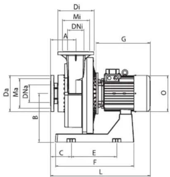
text_image
Di Mi DNi A G Da Ma DNa B C E F L O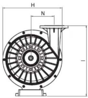
text_image
H N -| KIVU PUMP WITH OR WITHOUT PREFILTER / DIMENSIONS (mm) | ||||||||||||||||||||||||||||
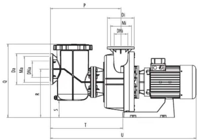
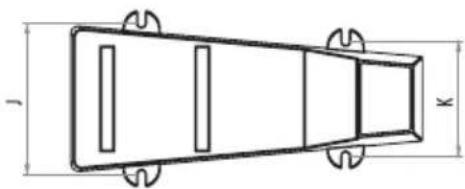
| PREFILTER | HP | A | B | C | Da | Di | DNa | Da | DNi | E | F | G | H | I | J | K | L | Ma | Mi | N | O | P | Q | R | S | T | U | |
| 63042 | 63042-0890 | 3 | 154 | 306 | 126 | 220 | 220 | 100-4" | 100-4" | 279 | 480 | 320 | 460 | 561 | 206 | 157 | 598 | 180 | 180 | 182 | 200 | 440 | 610 | 462 | 154 | 313 | 882 | 100 |
| 66047 | 66047-0890 | |||||||||||||||||||||||||||
| 63043 | 63043-0890 | 4 | 154 | 306 | 126 | 220 | 220 | 100-4" | 100-4" | 279 | 480 | 320 | 460 | 561 | 206 | 157 | 598 | 180 | 180 | 182 | 200 | 440 | 610 | 462 | 154 | 1313 | 882 | 100 |
| 66048 | 66048-0890 | |||||||||||||||||||||||||||
| 63044 | 63044-0890 | 5,5 | 154 | 306 | 126 | 220 | 220 | 100-4" | 100-4" | 279 | 480 | 345 | 460 | 561 | 206 | 157 | 623 | 180 | 180 | 182 | 200 | 440 | 610 | 462 | 154 | 313 | 906 | 100 |
| 66049 | 66049-0890 | |||||||||||||||||||||||||||
TECHNICAL CARACTERISTICS / RENSEIGNEMENTS TECHNIQUES / CARACTERÍSTICAS TÉCNICAS / DATI TECHNICI / TECHNISCHE ANGABEN / CARACTERISTICAS TECNICAS
text_image
P Di Mi DNi Da Ma DNa R S T U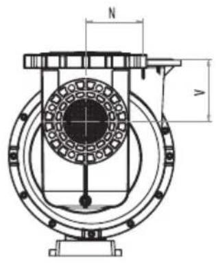
text_image
N V▲ KIVU PUMP WITH PREFILTER
KIVU PUMP WITHOUT PREFILTER
natural_image
Technical line drawing of a symmetrical mechanical component with labeled dimensions (no text or symbols)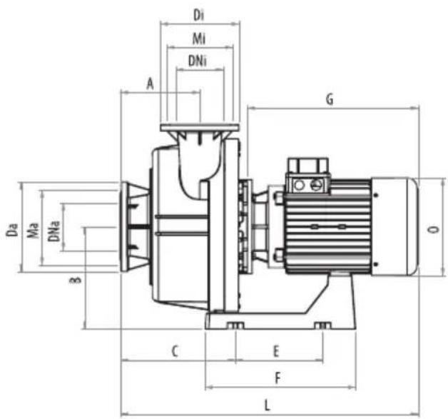
text_image
Di Mi DNi A G Da Ma DNa B C E F L O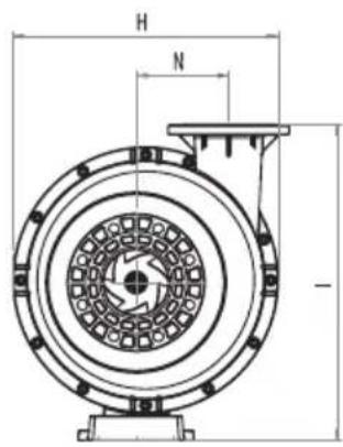
text_image
H N -| KIVU PUMP WITH OR WITHOUT PREFILTER / DIMENSIONS (mm) | ||||||||||||||||||||||||||||||||||||||||||
| PREFILTER | HP | A | B | C | Da | Di | DNa | Da | DNi | E | F | G | H | I | J | K | L | N | O | P | Q | R | S | T | U | V | Ma | MiWITH | WITHOUT | |||||||||||||
| 56633 | 56633-0890 | 7,5 | 254 | 326 | 141 | 285 | 250 | 150-6" | 125-5" | 279 | 480 | 410 | 550 | 653 | 206 | 157 | 815 | 192 | 256 | 653 | 677 | 446 | 157 | 540 | 1215 | 208 | 240 | 210 | ||||||||||||||
| 56634 | 56634-0890 | |||||||||||||||||||||||||||||||||||||||||
| 56635 | 56635-0890 | 10 | 254 | 326 | 141 | 285 | 250 | 150-6" | 125-5" | 279 | 480 | 445 | 550 | 653 | 206 | 157 | 850 | 192 | 256 | 653 | 677 | 446 | 157 | 540 | 1250 | 208 | 240 | 210 | ||||||||||||||
| 56637 | 56637-0890 | |||||||||||||||||||||||||||||||||||||||||
| 56638 | 56638-0890 | 15 | 254 | 326 | 271 | 285 | 250 | 150-6" | 125-5" | 279 | 480 | 545 | 550 | 653 | 206 | 157 | 950 | 192 | 312 | 653 | 677 | 446 | 157 | 670 | 1350 | 208 | 240 | 210 | ||||||||||||||
| 56639 | 56639-0890 | |||||||||||||||||||||||||||||||||||||||||
line
| Flow (m³/h) | Head (mmH) | dBA | |-------------|------------|-------| | 0 | 17.0 | 68.0 | | 10 | 16.8 | 67.8 | | 20 | 16.6 | 67.6 | | 30 | 16.4 | 67.4 | | 40 | 16.2 | 67.2 | | 50 | 16.0 | 67.0 | | 60 | 15.8 | 66.8 | | 70 | 15.6 | 66.6 | | 80 | 15.4 | 66.4 | | 90 | 15.2 | 66.2 | | 100 | 15.0 | 66.0 | | 110 | 14.8 | 65.8 | | 120 | 14.6 | 65.6 | | 130 | 14.4 | 65.4 | | 140 | 14.2 | 65.2 | | 150 | 14.0 | 65.0 | | 160 | 13.8 | 64.8 | | 170 | 13.6 | 64.6 | | 180 | 13.4 | 64.4 | | 190 | 13.2 | 64.2 | | 200 | 13.0 | 64.0 | | 210 | 12.8 | 63.8 | | 220 | 12.6 | 63.6 | | 230 | 12.4 | 63.4 | | 240 | 12.2 | 63.2 | | 250 | 12.0 | 63.0 | | 260 | 11.8 | 62.8 | | 270 | 11.6 | 62.6 | | 280 | 11.4 | 62.4 | | 290 | 11.2 | 62.2 | | 300 | 11.0 | 62.0 | | 310 | 10.8 | 61.8 | | 320 | 10.6 | 61.6 | | 330 | 10.4 | 61.4 | | 340 | 10.2 | 61.2 | | 350 | 10.0 | 61.0 | | 360 | 9.8 | 60.8 | | 370 | 9.6 | 60.6 | | 380 | 9.4 | 60.4 | | 390 | 9.2 | 60.2 | | 400 | 9.0 | 60.0 | | 410 | 8.8 | - | | 420 | 8.6 | - | | 430 | 8.4 | - | | 440 | 8.2 | - | | 450 | 8.0 | - | | 460 | - | - | | 470 | - | - | | 480 | - | - | | 490 | - | - | | 500 | - | - | | - | - | - | | - | - | - | | - | - | - | | - | - | - | | - | - | - | | - | - | - | | - | - | - | | - | - | - | | - | - | - | | - | - | - | | -3 | - | - | | -3 | - | - | | -3 | - | - | | -3 | - | - | | -3 | - | - | | -3 | - | - | | -3 | - | - | | -3 | - | - | | -3 | - | - | | -3 (with label) | - | - | | - (with label) | - | - | | - (with label) | - | - | | - (with label) | - | - | | - (with label) | - | - | | - (with label) | - | - | | - (with label) | - | - | | - (with label) | - | - | | - (with label) | - | - | | - (with label) | - | - | | - (with label) | - | - | | - (with label) | - | - | | - (with label) | - | - | | - (with label) | - | - | | - (with label) | - | + | | - (with label) | + | + | | - (with label) | + | + | | - (with label) | + | + | | - (with label) | + | + | | - (with label) | + | + | | - (with label) | + | + | | - (with label) | + | + | | - (with labeled) | + | + | | - (with labeled) | + | + | | - (with labeled) | + | + | | - (with labeled) | + | + | | - (with labeled) | + | + | | - (with labeled) | + | + | | - (with labeled) | + | + | | | - (with labeled) | + | + | | - (with labeled) | + | + | | - (with labeled) | + | + | | - (with labeled) | + | + | | - (with labeled) | + | + | | - (with labeled) | + | + | | - (with labeled) |+ | + | | - (with labeled) | + | + | | - (with labeled) | + | + | | - (with labeled) | + | + | | - (with labeled) | + | + | | - (with labeled) | + | + | | - (with labeled) | + | + | | - (With labeled) (-) | | | | (With labeled) (-) | | | | (With labeled) (-) | | | | (With labeled) (-) | | | | (With labeled) (-) | | | | (With labeled) (-) | | | | (With labeled) (-) | | | | (With labeled) (-) | | | | (With labeled) (-) | | | | (With labeled) (-) | | | | (With labeled) (-) | | | | (With labeled) (-) | | | | (With labeled) (-) | | | | (With labeled) (-) | | | | (With labeled) (-) |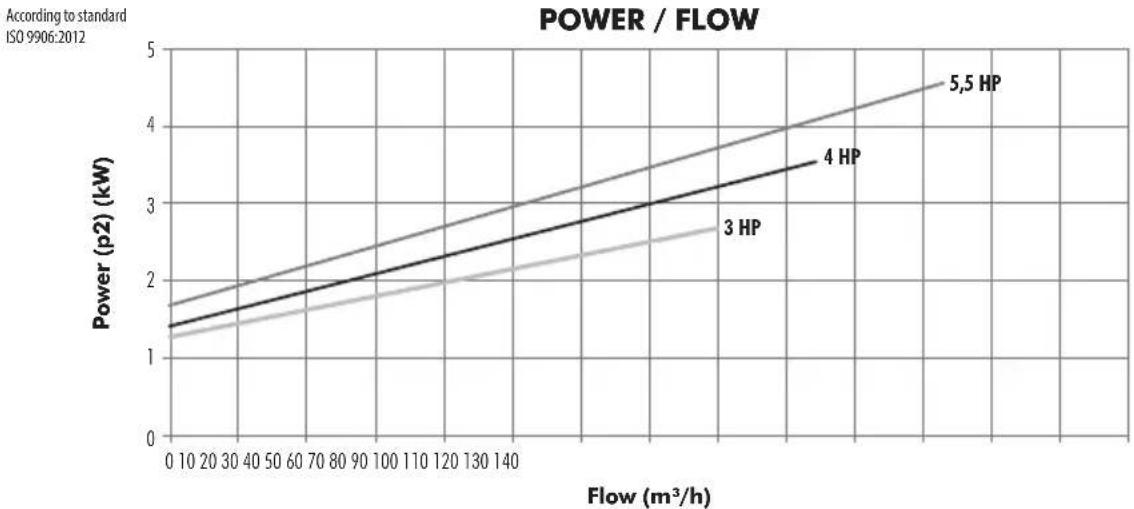
line
| Flow (m³/h) | 3 HP (kW) | 4 HP (kW) | 5.5 HP (kW) | |-------------|-----------|-----------|-------------| | 0 | 1.3 | 1.5 | 1.7 | | 10 | 1.4 | 1.6 | 1.8 | | 20 | 1.5 | 1.7 | 1.9 | | 30 | 1.6 | 1.8 | 2.0 | | 40 | 1.7 | 1.9 | 2.1 | | 50 | 1.8 | 2.0 | 2.2 | | 60 | 1.9 | 2.1 | 2.3 | | 70 | 2.0 | 2.2 | 2.4 | | 80 | 2.1 | 2.3 | 2.5 | | 90 | 2.2 | 2.4 | 2.6 | | 100 | 2.3 | 2.5 | 2.7 | | 110 | 2.4 | 2.6 | 2.8 | | 120 | 2.5 | 2.7 | 2.9 | | 130 | 2.6 | 2.8 | 3.0 | | 140 | 2.7 | 2.9 | 3.1 | | 150 | 2.8 | 3.0 | 3.2 | | 160 | 2.9 | 3.1 | 3.3 | | 170 | 3.0 | 3.2 | 3.4 | | 180 | 3.1 | 3.3 | 3.5 | | 190 | 3.2 | 3.4 | 3.6 | | 200 | 3.3 | 3.5 | 3.7 | | 210 | 3.4 | 3.6 | 3.8 | | 220 | 3.5 | 3.7 | 3.9 | | 230 | 3.6 | 3.8 | 4.0 | | 240 | 3.7 | 3.9 | 4.1 | | 250 | 3.8 | 4.0 | 4.2 | | 260 | 3.9 | 4.1 | 4.3 | | 270 | 4.0 | 4.2 | 4.4 | | 280 | 4.1 | 4.3 | 4.5 | | 290 | 4.2 | 4.4 | 4.6 | | 300 | 4.3 | 4.5 | 4.7 | | 310 | 4.4 | 4.6 | 4.8 | | 320 | 4.5 | 4.7 | 4.9 | | 330 | 4.6 | 4.8 | 5.0 | | 340 | 4.7 | 4.9 | 5.1 | | 350 | 4.8 | 5.0 | 5.2 | | 360 | 4.9 | 5.1 | 5.3 | | 370 | 5.0 | 5.2 | 5.4 | | 380 | 5.1 | 5.3 | 5.5 | | 390 | 5.2 | 5.4 | 5.6 | | 400 | 5.3 | 5.5 | 5.7 | | Note: The data is already in CSV format as it is not available for this example of the original table structure and not included in the original table numbers from the original table numbers list above or below the original table numbers list above or below the original table numbers list above or below the original table numbers list above or below the original table numbers list above or below the original table numbers list above or below the original table numbers list above or below the original table numbers list above or below the original table numbers list above or below the original table numbers list above or below the original table numbers list above or below the original table numbers list above or below the original table numbers list above or below the original table number of squares in each cell, respectively, and in each cell, respectively in each cell, respectively in each cell, respectively in each cell, respectively in each cell, respectively in each cell, respectively in each cell, respectively in each cell, respectively in each cell, respectively in each cell, respectively in each cell, respectively in each cell, respectively in each cell, respectively in each cell, respectively in each cell, respectively in each cell, respectively in each cell, respectively in each cell, respectively in each cell, respectively in each cell, respectively in each cell, and respectively in each cell.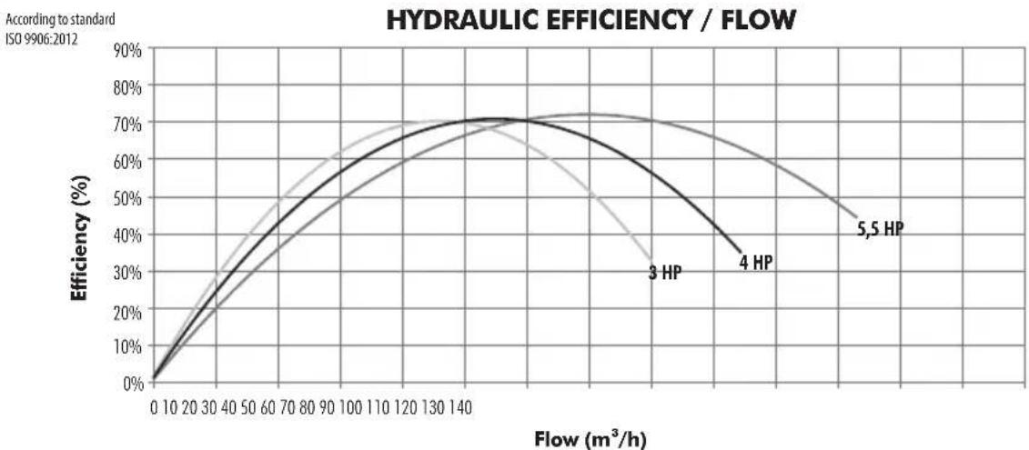
line
| Flow (m³/h) | 3 HP | 4 HP | 5.5 HP | |-------------|-------|-------|--------| | 0 | 0% | 0% | 0% | | 10 | ~10% | ~10% | ~10% | | 20 | ~20% | ~20% | ~20% | | 30 | ~30% | ~30% | ~30% | | 40 | ~40% | ~40% | ~40% | | 50 | ~50% | ~50% | ~50% | | 60 | ~60% | ~60% | ~60% | | 70 | ~65% | ~65% | ~65% | | 80 | ~68% | ~68% | ~68% | | 90 | ~70% | ~70% | ~70% | | 100 | ~71% | ~71% | ~71% | | 110 | ~71% | ~71% | ~71% | | 120 | ~71% | ~71% | ~71% | | 130 | ~71% | ~71% | ~71% | | 140 | ~71% | ~71% | ~71% | | 150 | ~70% | ~70% | ~70% | | 160 | ~68% | ~68% | ~68% | | 170 | ~65% | ~65% | ~65% | | 180 | ~62% | ~62% | ~62% | | 190 | ~58% | ~58% | ~58% | | 200 | ~55% | ~55% | ~55% | | 210 | ~52% | ~52% | ~52% | | 220 | ~50% | ~50% | ~50% | | 230 | ~48% | ~48% | ~48% | | 240 | ~45% | ~45% | ~45% | | 250 | ~42% | ~42% | ~42% | | 260 | ~40% | ~40% | ~40% | | 270 | ~38% | ~38% | ~38% | | 280 | ~36% | ~36% | ~36% | | 290 | ~34% | ~34% | ~34% | | 300 | ~32% | ~32% | ~32% | | 310 | ~30% | ~30% | ~30% | | 320 | ~28% | ~28% | ~28% | | 330 | ~26% | ~26% | ~26% | | 340 | ~24% | ~24% | ~24% | | 350 | ~22% | ~22% | ~22% | | 360 | ~20% | ~20% | ~20% | | 370 | ~18% | ~18% | ~18% | | 380 | ~16% | ~16% | ~16% | | 390 | ~14% | ~14% | ~14% | | 400 | ~12% | ~12% | ~12% | | 410 | ~10% | ~10% | ~10% | | 420 | ~8% | ~8% | ~8% | | 430 | ~6% | ~6% | ~6% | | 440 | ~4% | ~4% | ~4% | | 450 | ~2% | ~2% | ~2% | | 460 | - | - | - | | 470 | - | - | - | | 480 | - | - | - | | 490 | - | - | - | | 500 | - | - | - | | 510 | - | - | - | | 520 | - | - | - | | 530 | - | - | - | | 540 | - | - | - | | 550 | - | - | - | | 560 | - | - | - | | 570 | - | - | - | | 580 | - | - | - | | 590 | - | - | - | | 600 | - | - | - | | Note: The data is already in the required format as shown in the code. The values are estimated based on the provided code.| CODE KIVU PUMP WITH PREFILTER | |
| 63042 | ASTRAL KIVU 3HP 400/690V 50Hz |
| 63043 | ASTRAL KIVU 4HP 400/690V 50Hz |
| 63044 | ASTRAL KIVU 5,5HP 400/690V 50Hz |
| CODE KIVU PUMP WITH PREFILTER | |
| 66047 | ASTRAL KIVU 3HP 230/400V 50Hz |
| 66048 | ASTRAL KIVU 4HP 230/400V 50Hz |
| 66049 | ASTRAL KIVU 5,5HP 230/400V 50Hz |
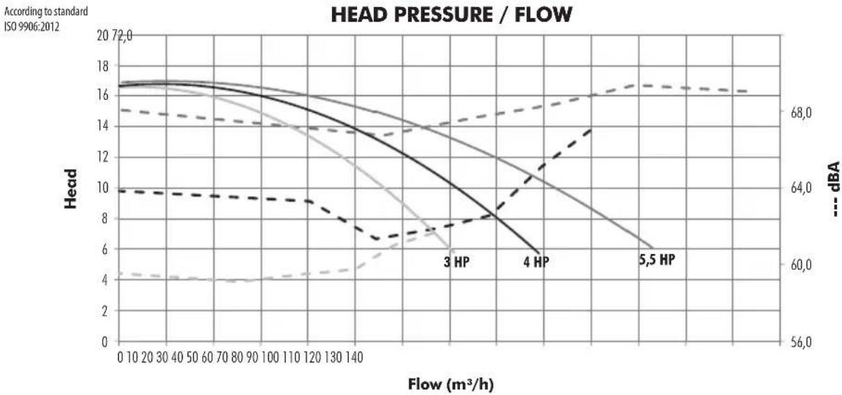
According to standard ISO 9906:2012
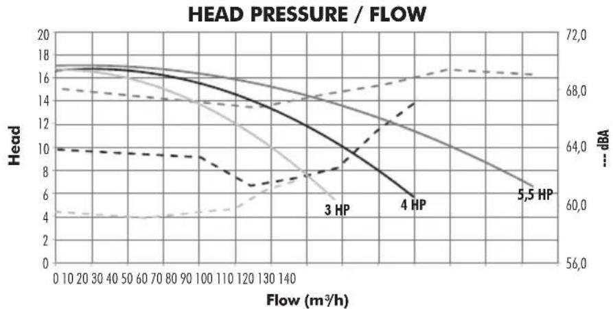
line
| Flow (m³/h) | Head (m³/h) | 3 HP (m³/h) | 4 HP (m³/h) | 5.5 HP (m³/h) | |-------------|-------------|-------------|-------------|---------------| | 0 | 17.0 | 10.0 | 10.0 | 10.0 | | 20 | 16.8 | 9.8 | 9.8 | 9.8 | | 40 | 16.5 | 9.5 | 9.5 | 9.5 | | 60 | 16.2 | 9.2 | 9.2 | 9.2 | | 80 | 15.8 | 8.8 | 8.8 | 8.8 | | 100 | 15.2 | 8.2 | 8.2 | 8.2 | | 120 | 14.5 | 7.5 | 7.5 | 7.5 | | 140 | 13.5 | 6.8 | 6.8 | 6.8 | | 160 | 12.0 | 6.0 | 6.0 | 6.0 | | 180 | 10.5 | 5.2 | 5.2 | 5.2 | | 200 | 9.0 | 4.5 | 4.5 | 4.5 | | 220 | 7.5 | 3.8 | 3.8 | 3.8 | | 240 | 6.0 | 3.0 | 3.0 | 3.0 | | 260 | 4.5 | 2.2 | 2.2 | 2.2 | | 280 | 3.0 | 1.5 | 1.5 | 1.5 | | 300 | 1.5 | 0.8 | 0.8 | 0.8 | | 320 | 0.0 | 0.0 | 0.0 | 0.0 | | 340 | -1.5 | -1.0 | -1.0 | -1.0 | | 360 | -3.0 | -2.0 | -2.0 | -2.0 | | 380 | -4.5 | -3.0 | -3.0 | -3.0 | | 400 | -6.0 | -4.0 | -4.0 | -4.0 | | 420 | -7.5 | -5.0 | -5.0 | -5.0 | | 440 | -9.0 | -6.0 | -6.0 | -6.0 | | 460 | -10.5 | -7.0 | -7.0 | -7.0 | | 480 | -12.0 | -8.0 | -8.0 | -8.0 | | 500 | -13.5 | -9.0 | -9.0 | -9.0 | | 520 | -15.0 | -10.0 | -10.0 | -10.0 | | 540 | -16.5 | -11.0 | -11.0 | -11.0 | | 560 | -18.0 | -12.0 | -12.0 | -12.0 | | 580 | -19.5 | -13.0 | -13.0 | -13.0 | | 600 | -21.0 | -14.0 | -14.0 | -14.0 | | 620 | -22.5 | -15.0 | -15.0 | -15.0 | | 640 | -24.0 | -16.0 | -16.0 | -16.0 | | 660 | -25.5 | -17.0 | -17.0 | -17.0 | | 680 | -27.0 | -18.0 | -18.0 | -18.0 | | 700 | -28.5 | -19.0 | -19.0 | -19.0 | | 720 | -30.0 | -20.0 | -20.0 | -20.0 | | 740 | -31.5 | -21.0 | -21.0 | -21.0 | | 760 | -33.0 | -22.0 | -22.0 | -22.0 | | 780 | -34.5 | -23.0 | -23.0 | -23.0 | | 800 | -36.0 | -24.0 | -24.0 | -24.0 | | 820 | -37.5 | -25.0 | -25.0 | -25.0 | | 840 | -39.0 | -26.0 | -26.0 | -26.0 | | 860 | -40.5 | -27.0 | -27.0 | -27.0 | | 880 | -42.0 | -28.0 | -28.0 | -28.0 | | 900 | -43.5 | -29.0 | -29.0 | -29.0 | | 920 | -45.0 | -30.0 | -30.0 | -30.0 | | 940 | -46.5 | -31.0 | -31.0 | -31.0 | | 960 | -48.0 | -32.0 | -32.0 | -32.0 | | 980 | -49.5 | -33.0 | -33.0 | -33.0 | | 1000 | -51 | -34.0 | -34.0 | -34.0 | | 1444 | -67 | — | — | — | | Total | — | — | — | — | | Head (m³/h) = ... (%) / dBA | | Total (m³/h) = ... (%) | | Head (m³/h) = ... (%) | | Head (m³/h) = ... (%) | | Head (m³/h) = ... (%) | | Head (m³/h) = ... (%) | | Head (m³/h) = ... (%) | | Head (m³/h) = ... (%) | | Head (m³/h) = ... (%) | | Head (m³/h) = ... (%):dBA | | Total (m³/h) = ... (%):dBA | | Head (m³/h) = ... (%):dBA | | Head (m³/h) = ... (%):dBA | | Head (m³/h) = ... (%):dBA | | Head (m³/h) = ... (%):dBA | | Head (m³/h) = ... (%):dBA | | Head (m³/h) = ... (%):dBA | | Head (m³/t) = ... (%):dBA | | Head (m³/t) = ... (%):dBA | | Head (m³/t) = ... (%):dBA | | Head (m³/t) = ... (%):dBA | | Head (m³/t) = ... (%):dBA | | Head (m³/t) = ... (%):dBA | | Head (m³/t) = ... %):dBA | | Head (m³/t) = ... %):dBA | | Head (m³/t) = ... %):dBA | | Head (m³/t) = ... %):dBA | | Head (m³/t) = ... %):dBA | | Head (m³/t) = ... %):dBA | | Head (m³/t) = ... %):dBA | | Head (m³/t) = ... %):dBA | | Head (m³/t) = ... %):dBA | | Head (m³/t) = ... %):dBA | | Head (m³/t) = ... %):dBA | | Head (m³/t) = ... %):dBA | | Head (m³/t) = ... %):dBA | | Head (-t/%) = ... (%):dBA | | Head (-t/%) = ... (%):dBA | | Head (-t/%) = ... (%):dBA | | Head (-t/%) = ... (%):dBA | | Head (-t/%) = ... (%):dBA | | Head (-t/%) = ... (%):dBA | | Head (-t/%) = ... (%):dBA | | Head (-t/%) = ... %):dBA | | Head (-t/%) = ... (%):dBA | | Head (-t/%) = ... %):dBA | | Head (-t/%) = ... %):dBA | | Head (-t/%) = ... %):dBA | | Head (-t/%) = ... %):dBA | | Head (-t/%) = ... %):dBA | | Head (-t/%) = ... %):dBA | | Head (-t/%) = ... %):dBA | | Head (-t/t) = ... (%):dBA | | Head (-t/t) = ... (%):dBA | | Head (-t/t) = ... (%):dBA | | Head (-t/t) = ... (%):dBA | | Head (-t/t) = ... (%):dBA | | Head (-t/t) = ... (%):dBA | | Head (-t/t) = ... (%):dBA | | Head (-t/%) = ... (%):dBA | | Head (-t/t) = ... (%):dBA | | Head (-t/t) = ... (%):dBA | | Head (-t/t) = ... (%):dBA | | Head (-t/t) = ... (%):dBA | | Head (-t/t) = ... (%):dBA | | Head (-t/t) = ... (%):dBA |According to standard ISO 9906:2012
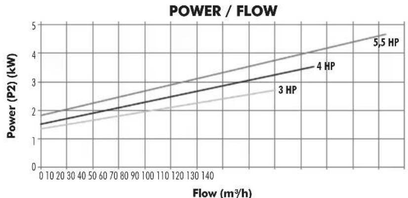
line
| Flow (m³/h) | 3 HP (kW) | 4 HP (kW) | 5.5 HP (kW) | |-------------|-----------|-----------|-------------| | 0 | 1.5 | 1.7 | 2.0 | | 20 | 1.6 | 1.8 | 2.2 | | 40 | 1.7 | 1.9 | 2.4 | | 60 | 1.8 | 2.0 | 2.6 | | 80 | 1.9 | 2.1 | 2.8 | | 100 | 2.0 | 2.2 | 3.0 | | 120 | 2.1 | 2.3 | 3.2 | | 140 | 2.2 | 2.4 | 3.4 | | 160 | 2.3 | 2.5 | 3.6 | | 180 | 2.4 | 2.6 | 3.8 | | 200 | 2.5 | 2.7 | 4.0 | | 220 | 2.6 | 2.8 | 4.2 | | 240 | 2.7 | 2.9 | 4.4 | | 260 | 2.8 | 3.0 | 4.6 | | 280 | 2.9 | 3.1 | 4.8 | | 300 | 3.0 | 3.2 | 5.0 | | 320 | 3.1 | 3.3 | 5.2 | | 340 | 3.2 | 3.4 | 5.4 | | 360 | 3.3 | 3.5 | 5.6 | | 380 | 3.4 | 3.6 | 5.8 | | 400 | 3.5 | 3.7 | 6.0 | | 420 | 3.6 | 3.8 | 6.2 | | 440 | 3.7 | 3.9 | 6.4 | | 460 | 3.8 | 4.0 | 6.6 | | 480 | 3.9 | 4.1 | 6.8 | | 500 | 4.0 | 4.2 | 7.0 | | 520 | 4.1 | 4.3 | 7.2 | | 540 | 4.2 | 4.4 | 7.4 | | 560 | 4.3 | 4.5 | 7.6 | | 580 | 4.4 | 4.6 | 7.8 | | 600 | 4.5 | 4.7 | 8.0 | | 620 | 4.6 | 4.8 | 8.2 | | 640 | 4.7 | 4.9 | 8.4 | | 660 | 4.8 | 5.0 | 8.6 | | 680 | 4.9 | 5.1 | 8.8 | | 700 | 5.0 | 5.2 | 9.0 | | 720 | 5.1 | 5.3 | 9.2 | | 740 | 5.2 | 5.4 | 9.4 | | 760 | 5.3 | 5.5 | 9.6 | | 780 | 5.4 | 5.6 | 9.8 | | 800 | 5.5 | 5.7 | 10.0 | | 820 | - | - | - | | 840 | - | - | - | | 860 | - | - | - | | 880 | - | - | - | | 900 | - | - | - | | 920 | - | - | - | | 940 | - | - | - | | 960 | - | - | - | | 980 | - | - | - | | 1000 | - | - | - | | - | - | - | - | | - | - | - | - | | - | - | - | - | | - | - | - | - | | - | - | - | - | | - | - | - | - | | - | - | - | - | | - | - | - | - | | - | - | - | - | | - | - | - | - | | - | - | - | - | | - | - | - | - | | - | - | - | - | | - | - | - | - | | - | - | - | - | | - | - | ~- ~- | ~- | | - | ~- ~- | ~- ~- | ~- | | - | ~- ~- | ~- ~- | ~- | | - | ~- ~- | ~- ~- | ~- | | - | ~- ~- | ~- ~- | ~- | | - | ~- ~- | ~- ~- | ~- | | Flow (m³/h) on Y-axis: Power (P2) for each HP level (HP) on X-axis; Power (P2) on Y-axis; Flow (m³/h) on X-axis; Power (P2) on Y-axis; Power (P2) on Y-axis; Power (P2) on X-axis; Power (P2) on Y-axis; Power (P2) on X-axis; Power (P2) on Y-axis; Power (P2) on X-axis; Power (P2) on Y-axis; Power (P2) on X-axis; Power (P2) on Y-axis; Power (P2) on X-axis; Power (P2) on Y-axis; Power (P2) on X-axis; Power (P2) on Y axis; Power (P2) on Y axis; Power (P2) on Y axis; Power (P2) on Y axis; Power (P2) on Y axis; Power (P2) on X axis; Power (P2) on Y axis; Power (P2) on X axis; Power (P2) on Y axis; Power (P2) on X axis; Power (P2) on Y axis; Power (P2) on X axis; Power (P2) on Y axis; Power (P2) on X axis; Power (P2) on Y axis; Power (P2) on X axis; Power (P2) on Y axes; Power (P2) on Y axes; Power (P2) on Y axes; Power (P2) on Y axes; Power (P2) on Y axes; Power (P2) on Y axes; Power (P2) on Y axes; Power (P2) on Y axes; Power (P2) on Y axes; Power (P2) on Y axes; Power (P2) on Y axes; Power (P2) on Y axes, Power (P2) on Y-axis; Power (P2) on Y-axis, Power (P2) on Y-axis, Power (P2) on Y-axis, Power (P2) on Y-axis, Power (P2) on Y-axis, Power (P2) on Y-axis, Power (P2) on Y-axis, Power (P2) on Y-axis, Power (P2) on Y-axis, Power (P2) on Y-axis, Power (P2) on Y-axis, Power (P2) on Y-axis, Total/Total/Total/Total/Total/Total/Total/Total/Total/Total/Total/Total/Total/Total/Total/Total/Total/Total/Total/Total/Total/Total/Total/Total/Total/Total/Total/Total/Total/Total/Total/Total/Total/Total/Total/Total/Total/Total/Total/Total/Total/Total/Total/Total/Total/Total/Total/Total/Total/Total/Total/ Total / Total / Total / Total / Total / Total / Total / Total / Total / Total / Total / Total / Total / Total / Total / Total / Total / Total / Total / Total / Total / Total / Total / Total / Total / Total / Total / Total / Total / Total / Total / Total / Total / Total / Total / Total / Total / Total / Total / Total / Total / Total / Total / Total / Total / Total / Total / Total / Total / Total / Total * = (-).According to standard ISO 9906:2012
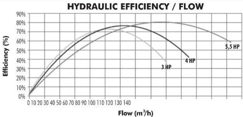
line
| Flow (m³/h) | 3 HP | 4 HP | 5.5 HP | |-------------|-------|-------|--------| | 0 | 0% | 0% | 0% | | 10 | ~10% | ~10% | ~10% | | 20 | ~20% | ~20% | ~20% | | 30 | ~30% | ~30% | ~30% | | 40 | ~40% | ~40% | ~40% | | 50 | ~50% | ~50% | ~50% | | 60 | ~60% | ~60% | ~60% | | 70 | ~65% | ~65% | ~65% | | 80 | ~70% | ~70% | ~70% | | 90 | ~72% | ~72% | ~72% | | 100 | ~74% | ~74% | ~74% | | 110 | ~75% | ~75% | ~75% | | 120 | ~76% | ~76% | ~76% | | 130 | ~77% | ~77% | ~77% | | 140 | ~78% | ~78% | ~78% | | 150 | ~79% | ~79% | ~79% | | 160 | ~80% | ~80% | ~80% | | 170 | ~80% | ~80% | ~80% | | 180 | ~80% | ~80% | ~80% | | 190 | ~80% | ~80% | ~80% | | 200 | ~80% | ~80% | ~80% | | 210 | ~80% | ~80% | ~80% | | 220 | ~80% | ~80% | ~80% | | 230 | ~80% | ~80% | ~80% | | 240 | ~80% | ~80% | ~80% | | 250 | ~80% | ~80% | ~80% | | 260 | ~80% | ~80% | ~80% | | 270 | ~80% | ~80% | ~80% | | 280 | ~80% | ~80% | ~80% | | 290 | ~80% | ~80% | ~80% | | 300 | ~80% | ~80% | ~80% | | 310 | ~80% | ~80% | ~80% | | 320 | ~80% | ~80% | ~80% | | 330 | ~80% | ~80% | ~80% | | 340 | ~80% | ~80% | ~80% | | 350 | ~80% | ~80% | ~80% | | 360 | ~80% | ~80% | ~80% | | 370 | ~80% | ~80% | ~80% | | 380 | ~80% | ~80% | ~80% | | 390 | ~80% | ~80% | ~80% | | 400 | ~80% | ~80% | ~80% | | 410 | ~80% | ~80% | ~80% | | 420 | ~80% | ~80% | ~80% | | 430 | ~80% | ~80% | ~80% | | 440 | ~80% | ~80% | ~80% | | 450 | ~80% | ~80% | ~80% | | 460 | ~80% | ~80% | ~80% | | 470 | ~80% | ~80% | ~80% | | 480 | ~80% | ~80% | ~80% | | 490 | ~80% | ~80% | ~80% | | 500 | ~80% | ~80% | ~80% | | 510 | ~80% | ~80% | ~80% | | 520 | ~80% | ~80% | ~80% | | 530 | ~80% | ~80% | ~80% | | 540 | ~80% | ~80% | ~80% | | 550 | ~80% | ~80% | ~80% | | 560 | ~80% | ~80% | ~80% | | 570 | ~80% | ~80% | ~80% | | 580 | ~80% | ~80% | ~80% | | 590 | ~80% | ~80% | ~80% | | 600 | ~80% | ~80% | ~80% | | Note: The data is in a format where the values are estimated based on the provided code. The numbers present in the code above the bars are not explicitly provided in the original code. There is only one data series labeled '3 HP' and '4 HP'.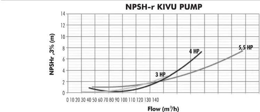
line
| Flow (m³/h) | NPSHr,3% (m) | |-------------|--------------| | 40 | 1.0 | | 140 | 2.5 | | 150 | 7.5 || CODE KIVU PUMP WITHOUT PREFILTER | |
| 63042-0890 | ASTRAL KIVU 3HP 400/690V 50Hz |
| 63043-0890 | ASTRAL KIVU 4HP 400/690V 50Hz |
| 63044-0890 | ASTRAL KIVU 5,5HP 400/690V 50Hz |
| CODE KIVU PUMP WITHOUT PREFILTER | |
| 66047-0890 | ASTRAL KIVU 3HP 230/400V 50Hz |
| 66048-0890 | ASTRAL KIVU 4HP 230/400V 50Hz |
| 66049-0890 | ASTRAL KIVU 5,5HP 230/400V 50Hz |
According to standard ISO 9906:2012
line
| Flow (m³/h) | Head (m³/h) | Head (dB) | |-------------|-------------|-----------| | 0 | 22 | 74 | | 40 | 20 | 72 | | 80 | 18 | 70 | | 120 | 16 | 68 | | 160 | 14 | 66 | | 200 | 12 | 64 | | 240 | 10 | 62 | | 280 | 8 | 60 | | 320 | 6 | 62 |According to standard ISO 9906:2012
line
| Flow (m³/h) | 15 HP | 10 HP | 7.5 HP | |-------------|-------|-------|--------| | 0 | 6.0 | 4.0 | 3.0 | | 20 | 7.0 | 5.0 | 4.0 | | 40 | 8.0 | 6.0 | 5.0 | | 60 | 9.0 | 7.0 | 6.0 | | 80 | 10.0 | 8.0 | 7.0 | | 100 | 11.0 | 9.0 | 8.0 | | 120 | 12.0 | 10.0 | 9.0 | | 140 | 13.0 | 11.0 | 10.0 | | 160 | 14.0 | 12.0 | 11.0 | | 180 | 15.0 | 13.0 | 12.0 | | 200 | 16.0 | 14.0 | 13.0 | | 220 | 17.0 | 15.0 | 14.0 | | 240 | 18.0 | 16.0 | 15.0 | | 260 | 19.0 | 17.0 | 16.0 | | 280 | 20.0 | 18.0 | 17.0 | | 300 | 21.0 | 19.0 | 18.0 | | 320 | 22.0 | 20.0 | 19.0 |According to standard ISO 9906:2012
line
| Flow (m³/h) | 7.5 HP | 10 HP | 15 HP | |-------------|--------|-------|-------| | 0 | 0% | 0% | 0% | | 20 | ~30% | ~25% | ~20% | | 40 | ~50% | ~45% | ~40% | | 60 | ~65% | ~60% | ~55% | | 80 | ~75% | ~70% | ~65% | | 100 | ~80% | ~75% | ~70% | | 120 | ~80% | ~78% | ~72% | | 140 | ~80% | ~78% | ~73% | | 160 | ~78% | ~75% | ~72% | | 180 | ~75% | ~72% | ~70% | | 200 | ~70% | ~68% | ~65% | | 220 | ~65% | ~65% | ~60% | | 240 | ~60% | ~62% | ~55% | | 260 | ~55% | ~60% | ~52% | | 280 | ~50% | ~58% | ~50% | | 300 | ~45% | ~55% | ~48% | | 320 | ~40% | ~52% | ~45% |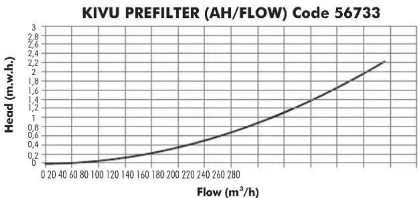
line
| Flow (m³/h) | Head (m.w.h.) | | ----------- | ------------- | | 0 | 0 | | 40 | 0.1 | | 80 | 0.2 | | 120 | 0.3 | | 160 | 0.4 | | 200 | 0.5 | | 240 | 0.7 | | 280 | 1.0 | | 320 | 1.4 | | 360 | 1.8 | | 400 | 2.2 || CODE KIVU PUMP WITH PREFILTER | |
| 56633 | ASTRAL KIVU 7,5HP 230/400V 50Hz |
| 56634 | ASTRAL KIVU 7,5HP 400/690V 50Hz |
| 56635 | ASTRAL KIVU 10HP 230/400V 50Hz |
| CODE KIVU PUMP WITH PREFILTER | |
| 56637 | ASTRAL KIVU 10HP 400/690V 50Hz |
| 56638 | ASTRAL KIVU 15HP 230/400V 50Hz |
| 56639 | ASTRAL KIVU 15HP 400/690V 50Hz |
According to standard ISO 9906:2012
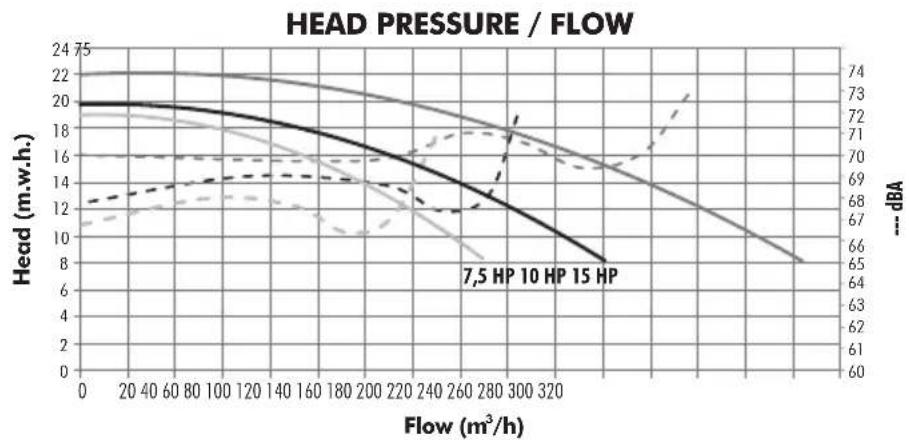
According to standard ISO 9906:2012
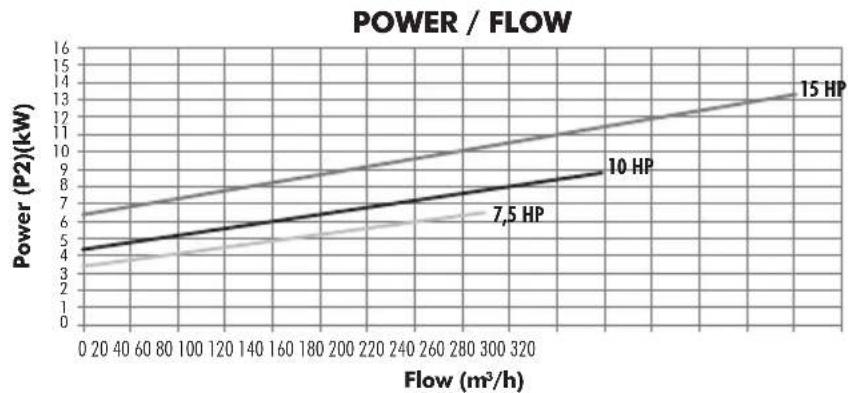
line
| Flow (m³/h) | 7.5 HP | 10 HP | 15 HP | |-------------|--------|-------|-------| | 0 | 4.0 | 6.0 | 6.5 | | 320 | 6.0 | 9.0 | 13.0 |According to standard ISO 9906:2012
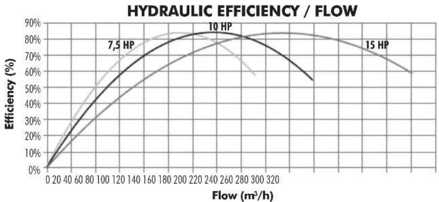
line
| Flow (m³/h) | 7.5 HP | 10 HP | 15 HP | |-------------|--------|-------|-------| | 0 | 0% | 0% | 0% | | 40 | ~20% | ~30% | ~40% | | 80 | ~40% | ~60% | ~70% | | 120 | ~60% | ~75% | ~80% | | 160 | ~70% | ~80% | ~85% | | 200 | ~75% | ~82% | ~85% | | 240 | ~78% | ~83% | ~85% | | 280 | ~75% | ~82% | ~85% | | 320 | ~70% | ~80% | ~85% | | 360 | ~65% | ~75% | ~80% | | 400 | ~60% | ~70% | ~75% |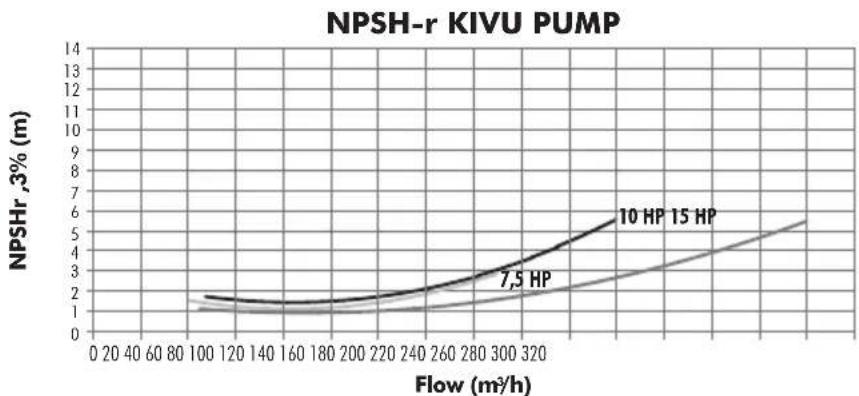
line
| Flow (m³/h) | 7.5 HP | 10 HP | 15 HP | |-------------|--------|-------|-------| | 0 | 1.0 | 1.5 | 2.0 | | 100 | 1.2 | 1.8 | 2.5 | | 200 | 1.5 | 2.2 | 3.0 | | 300 | 2.0 | 3.0 | 4.0 | | 400 | 2.5 | 4.0 | 5.0 | | 500 | 3.0 | 5.0 | 6.0 || CODE KIVU PUMP WITHOUT PREFILTER | |
| 56633-0890 | ASTRAL KIVU 7,5HP 230/400V 50Hz |
| 56634-0890 | ASTRAL KIVU 7,5HP 400/690V 50Hz |
| 56635-0890 | ASTRAL KIVU 10HP 230/400V 50Hz |
| CODE KIVU PUMP WITHOUT PREFILTER | |
| 56637-0890 | ASTRAL KIVU 10HP 400/690V 50Hz |
| 56638-0890 | ASTRAL KIVU 15HP 230/400V 50Hz |
| 56639-0890 | ASTRAL KIVU 15HP 400/690V 50Hz |
GUARANTEE CERTIFICATE
1. GENERAL TERMS
1.1. In accordance with this provisions, the seller guarantees that the Astral Product corresponding to this guarantee ("The Product") doesn't have any default in conformity at this time of delivery.
1.2. The guarantee term for the product is two (2) years and will be calculate from the date of delivery to the purchaser.
1.3. In the event of any default in conformity of the product and the purchaser notifies the seller of such default during the guarantee period, the seller is obliged to repair o replace the Product at its own cost in the place that he consider convenient, unless it is impossible or disproportionate.
1.4. When it is not possible to repair or replace, the purchaser may request a proportional reduction in the price, or, if the default in conformity is sufficient significant, the termination of the contract.
1.5. The parts replaced or repaired under this guarantee will not extend the guarantee term of the Product, although will have their own guarantee.
1.6. In order for this guarantee to come into effect, the purchaser must prove the date of acquisition and delivery of the Product.
1.7. If after six months from the delivery of the Product to the purchaser, a default of the conformity of the product is notified, the purchaser must prove the origin and existence of said defect.
1.8. This Guarantee Certificate does not limit or prejudge the rights corresponding to the consumers by virtue of national compulsory standards.
2. INDIVIDUAL TERMS
2.1. This Guarantee covers the following AstralPool products and product ranges: "Filtration Pumps".
2.2. This Guarantee Certificate will be applicable exclusively in countries of the European Union.
2.3. In order for this guarantee to be effective the purchaser must strictly follow the manufacturer's instructions included in the documentation accompanying the Product, if said documentation is applicable depending on the range and model of the Product
2.4. When a schedule is given to replace, maintain or clean certain parts or components of the Product, the guarantee will only be valid if this schedule has been followed correctly.
3. LIMITATIONS
3.1. This guarantee will apply exclusively to sales made to consumers. A “consumer”, is understood to be the person who acquires the Product for purposes not connected with his professional activity.
3.2. No guarantee is given for the normal wear through using the product. With regard to parts, components and/or expendable equipment such as mechanical seals, bearings and water tightness, the documentation accompanying the product will be applicable, as the case may be.
3.3. The guarantee does not cover accessory elements of the product "Filtration pump" not explicitly included on it, such as panel board, converter, protection devices, etc..
3.4. The guarantee covers Product's failures originated only and exclusively by materials defect and/or performance works. The guarantee doesn't cover cases such as the Product: (i) has been object of an incorrect handling; (ii) has been installed, repaired, maintained or manipulated for an non-authorized person or (iii) has been repaired or maintained with non original spares. It's out of the present guarantee the slight damages originated by accidental tears or inadequate as:
- Pump working without water
- Incorrect dosification of chemical products on the swimming pool
- Water damage originate in external elements to the pumping conditions.
- Inadequate ventilation
- Use in different applications of swimming pool water filtration.
3.5. The guarantee does not cover cases of incorrect installation or start-up unless said installation or start-up is included in the sales contract of the Product and has performed by the seller or under his responsibility. This cases are covered by the installer or the seller who installed the product.
CERTIFICAT DE GARANTIE
1. ASPECTS GENERAUX
- Declares under their own responsibility that all the pumps: KIVU, Three-phase.
Manufactured since 29/12/2009, independent of the serial number, are in compliance with:
• 2006/42/EC Machine Directive Safety prescriptions.
• 2004/108/EC Electromagnetic compatibility Directive.
• 2006/95/EC Low voltage Directive.
• 2000/14/EC Noise émission Directive.
• EN 60335-2-41/A1:2004.
D. José Manuel Aquilue Ferrer, Managing Director of Metalast S.A.U.
Cod. 56633-0009 / Rev. 03
- We reserve the right to change all or part of the features of the articles or contents of this document, without prior notice.
- Nous nous réservons le droit de modifier totalement ou en partie les caractéristiques de nos articles ou le contenu de ce document sans préavis.
- Nos reservamos el derecho de cambiar total o parcialmente las características de nuestros artículos o contenido de este documento sin previo aviso.
- Ci riserviamo il diritto di cambiare totalmente o parzialmente le caratteristiche tecniche dei nostri prodotti ed il contenuto di questo documento senza nessum preavviso.
- Wir behalten uns das recht vor, die merkmale unserer produkte und den inhalt dieser beschreibung ohne vorherige unkündigung ganz oder teilweise zu ändern.
- Reservamo-nos no direito de alterar, total ou parcialmente características dos nossos artigos ou o conteúdo deste documento sem aviso prévio.