Telescopic Glass 691 - Basket NOVY - Free user manual and instructions
Find the device manual for free Telescopic Glass 691 NOVY in PDF.


| Brand | Novy |
| Model | Telescopic Glass 691 |
| Product type | Telescopic range hood |
| Material | Stainless steel and glass |
| Number of speeds | 3 (I, II, III) |
| Lighting | Replaceable LED |
| Grease filter | Aluminum, dishwasher safe |
| Recirculation filter (optional) | Monoblock, oven-regenerable (12 times max) |
| Power supply | 220-240 V, 50 Hz, with earth plug |
| Warranty | 60 months (domestic use, according to country) |
| Extraction type | Recirculation or external evacuation |
| Controls | Electronic, with separate lighting |
| Automatic shut-off function | Yes, by closing the drawer |
| Safety | Automatic reset thermal contact |
| Exterior cleaning | Damp cloth and mild detergent, avoid harsh products |
| Spare parts | LED lamp, grease filter, recirculation filter |
| Installation | By qualified installer, before commissioning |
| Filter maintenance | Every 6 months (1-2h/day) |
| User manual | Available in French, German, English, Dutch |
Frequently Asked Questions - Telescopic Glass 691 NOVY
User questions about Telescopic Glass 691 NOVY
0 question about this device. Answer the ones you know or ask your own.
Ask a new question about this device
Download the instructions for your Basket in PDF format for free! Find your manual Telescopic Glass 691 - NOVY and take your electronic device back in hand. On this page are published all the documents necessary for the use of your device. Telescopic Glass 691 by NOVY.
USER MANUAL Telescopic Glass 691 NOVY
natural_image
Technical line drawing of a mechanical component with a conical top and rectangular base (no text or symbols)EN Operating and installation Instructions p. 11
661/16 - 662/16 691/16 - 692/16
ALGEMENE INFORMATIE
natural_image
Diagram of a structural support frame with red arrows indicating direction, no text or symbols presentnatural_image
Technical line drawing of a mechanical component with three upward-pointing arrows indicating motion or force directions (no text or symbols present)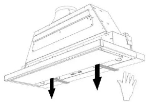
natural_image
Technical line drawing of a mechanical assembly with two downward arrows indicating force or movement (no text or symbols present)text_image
Technical diagram showing a mechanical or electrical component with labeled parts A and B, including directional arrows and circular indicators.text_image
Technical diagram showing mechanical assembly with labeled components A, B, and C, including directional arrows indicating rotation or movement.natural_image
Diagram of a structural component with red arrows indicating direction, no text or symbols presentNettoyage:
natural_image
Technical line drawing of a mechanical component with three upward-pointing arrows indicating assembly or force direction (no text or symbols present)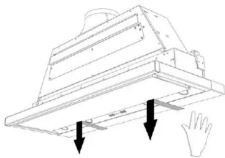
natural_image
Technical line drawing of a mechanical assembly with two downward arrows indicating force or movement (no text or symbols present)text_image
Technical diagram showing a mechanical or electrical component with labeled parts A and B, including directional arrows and circular indicators.text_image
Technical diagram showing mechanical assembly with labeled components A, B, and C, including directional arrows indicating rotation or movement.text_image
Diagram showing a circular component with labeled terminals and lightbulb symbols, possibly representing a mechanical or electrical component.natural_image
Diagram of a roof drainage system with red arrows indicating flow direction (no text or symbols)natural_image
Technical line drawing of a mechanical component with three upward-pointing arrows indicating direction (no text or symbols)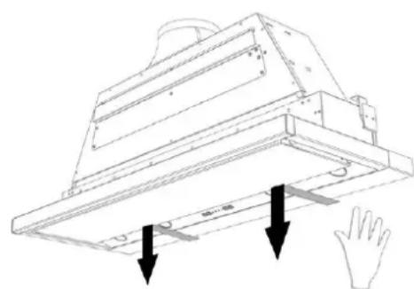
natural_image
Technical line drawing of a mechanical component with two downward arrows indicating force or movement (no text or symbols present)text_image
Technical diagram showing a mechanical or electrical component with labeled parts A and B, including directional arrows and circular components.text_image
Technical diagram showing mechanical assembly with labeled components A, B, and C, including directional arrows indicating motion or rotation.- Please read these operating instructions carefully. They contain information about installation, operation, safety and maintenance you need to be aware of.
• This hood is for domestic use only - It is recommended to have the installation done by a qualified professional. Any damage due to faulty or unprofessional installation relieves the manufacturer of any form of responsibility.
- Check the condition of the hood and the installation material before installing. Carefully remove the hood out of the packaging. Be careful not to use sharp knives to open the box.
- Please keep these instructions to pass on to future users.
- Disposal of transport packaging and old appliance
Your new appliance was sent to you in protective packaging. All utilised materials are environmentally safe and recyclable. Please help us by disposing of the packaging in an environmentally friendly manner.
Old appliances are not worthless rubbish. Valuable raw materials can be reclaimed by recycling old appliances. This appliance is identified according to the European Directive 2002/96/EC on waste electrical and electronic equipment. Please ask your dealer or inquire at your local authority about current means of disposal.
- Technical problem
In case of technical problems please contact Novy Service Department:
For Belgium: Tel.: 056/36.51.02
For France: Tel.: 03.20.94.06.62
For Germany: Tel.: 0511.54.20.771
For all other countries: your local installer or Novy Belgium: +32 (0)56/36.51.02
Please supply us with the model number of your hood. The model number can be found on the engraved plaque behind the filter.
You can make a note of the number here: ....
- For all remarks or questions to which this manual doesn't answer please contact our Customer Service:
For Belgium: Tel.: 056/36.51.01
For France: Tel.: 03.20.94.06.62
For Germany: Tel.: 0511.54.20.771
For all other countrys: your local installer or Novy Belgium: +32 (0)56/36.51.02
Use
NOTE: These operating instructions apply to several appliance models It is possible that individual features are described which do not apply to your appliance.
Air supply
When using a hood sufficient air flow is necessary. However large your kitchen may be, there is only so much air available in that space. Opening a door or window or the installation of a ventilation grid close to the hood insures a good quality of air flow.
Insufficient air flow will impair the extraction efficiency of your hood immensely.
Insufficient air flow can cause reflux from other air ducts such as chimneys or combustion appliances.
When using a cooker hood and appliances using energy other than electrical in the same space, the pressure in the room may not surpass 4 Pa (= 0.04mBar).
Safety
- Deep frying under the hood is only allowed under constant supervision.
- Under no circumstances is it allowed to flambé under the hood.
• In case of fire always switch off the hood. - Never extinguish burning fat or oil with water. Cover the pot with a well fitting lid or a burn-blanket.
Advice
For maximum efficiency please follow this advice:
- When cooking make sure pots are positioned properly under the hood surface.
- Activate the hood a few minutes prior to cooking.
- Switch the hood off 10 minutes after cooking is finished (delay function if present).
- Avoid drafts under the hood surface.
- When using induction: adapt the intensity of both hob and hood to the lowest possible level in order to avoid excessive creation of damp fumes.
Operation
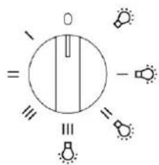
0 : the hood is switched off
: light
I, II, III : 3 speed levels without light
I, II, III + ⚙: 3 speed levels with light
text_image
= 0 = -Once the drawer is opened, the light and the fan can be turned on. By closing the drawer the light and the fan will be turned off.
A self-rectifying thermal contact makes sure that the motor is switched off when overheated. The motor will switch on again after is has cooled down. The cause of the overheating needs to be determined. This may be, for example, that the contents of the pan have caught fire, the motor fan is blocked or an object is (partly) closing off the exhaust opening.
Maintenance
Maintenance of the filter
With normal use (1 to 2 hours daily), regenerate the Monoblock recirculation filter every six months.
natural_image
Diagram of a structural component with red arrows indicating direction, showing internal structure and supports (no text or symbols)Access to the filter
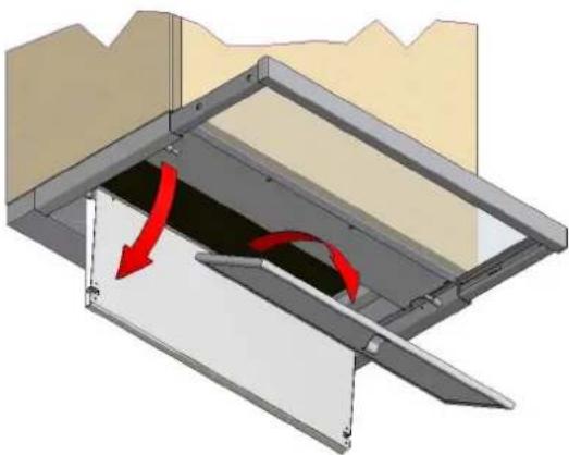
Remove the grease filters by pulling down the two stainless steel hinged lower cover plates at the front side, which covers the grease filters. Pull the two metal grease filters down by the little hook.
Cleaning the filter:
• in the dishwasher
- manually: in a hot solution of water and a liquid detergent. Rince and allow to dry completely
Important! The previous instructions need to be followed. If not an increased fire hazard may occur.
Maintenance of the hood
Please allow the lights to cool down sufficiently before cleaning the hood.
Use a soft, wet cloth and a mild detergent to clean the hood.
Never use aggressive, abrasive detergents or sponges. Bleach will damage stainless steel.
The stainless steel surfaces can be treated with Novy Inoxcleaner (906.060) after cleaning.
Recirculation (option)
If you have chosen for recirculation, please follow the instructions below.
Cleaning:
With normal use (1 to 2 hours daily), regenerate the Monoblock recirculation filter every six months.
Remove the Monoblock recirculation filter:
- Open the bottom plate with both hands and remove the aluminium grease filter from the hood.
- The Monoblock recirculation filter is found in its opening in the cooker hood. Remove it from the cooker hood.
Regenerate the Monoblock recirculation filter:
- The Monoblock can be regenerated up to 12 times. This is done in the oven.
- Place the filter in the oven for 1 hour at 120^ C. Provide sufficient fresh air in the room where the oven has been placed, as smells can be released. Smells can be released when baking certain kinds of fish. The best solution for this is to immediately regenerate the filter.
Place the Monoblock recirculation filter:
- Open the bottom plate with both hands and remove the aluminium grease filter from the hood.
- Place the Monoblock recirculation filter is its opening in the cooker hood.
- Put back the aluminium grease filter and close the bottom plate.
Replacing the led lighting
First, remove the power supply from the hood and allow the lighting to cool down sufficiently.
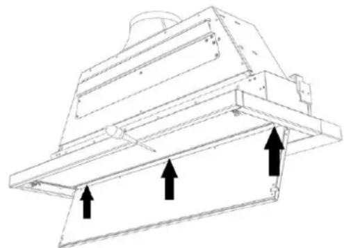
- Carefully press the spotlight holder; next, remove the spotlight holder by means of a tilting movement.
- Open de bottom plate and then loosen the screws and slide the cover forward and downward to loosen it from the cooker hood.
natural_image
Technical line drawing of a mechanical component with three upward-pointing arrows indicating motion or force directions (no text or symbols present)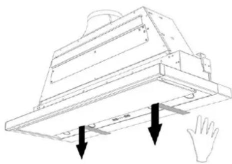
natural_image
Technical line drawing of a mechanical component with two downward arrows indicating force or movement (no text or symbols present)- Removing the LED lamp:
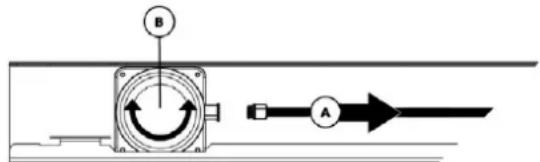
A. First disconnect the cable to the LED to be replaced. Disconnect by means of releasing the lock, by applying light pressure while at the same time pulling away.
B. Next, remove the LED to be replaced by making a gentle rotating movement to the left.
text_image
Technical diagram showing a mechanical or electrical component with labeled parts A and B, including directional arrows and circular motion indicators.- Mounting the new LED:
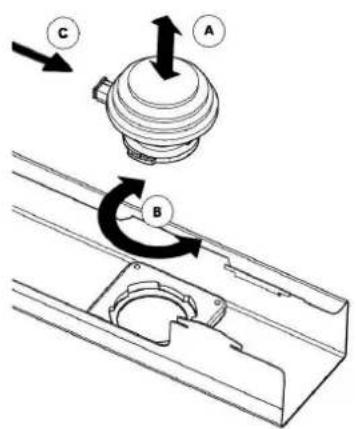
A. Place the new LED light into the locking ring.
B. Make a rotating movement to the right until the LED light is locked.
C. Connect the power cable.
D. Put back the cover and tighten the screws. Then close the bottom plate.
text_image
Technical diagram showing mechanical assembly with labeled components A, B, and C, including directional arrows indicating motion or rotation.Electrical connection
Electrical output: electrical cord + plug with ground. To be plugged into socket with ground.
Check for compatibility with information on type plate (behind filter).
Socket must be within reach.
Changes or replacement of the electrical cord should be performed by a professional only.
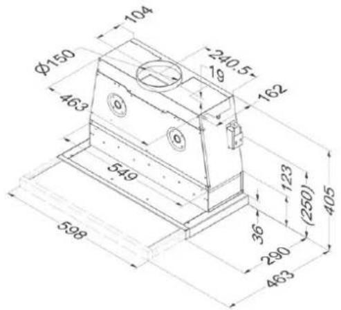
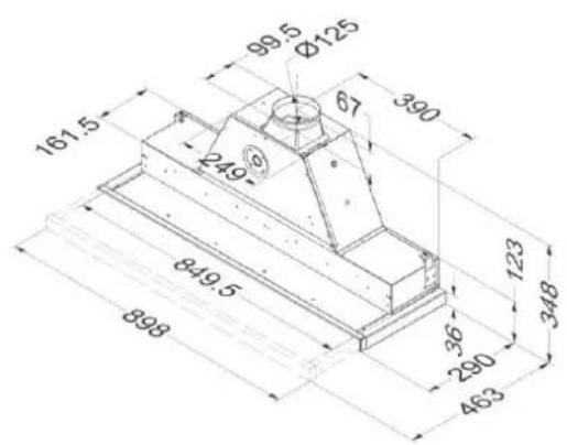
Dimensions: p. 18
Electrical scheme: p. 19-20
Afmetingen - Dimensions - Abmessungen - Dimensions
661
662
text_image
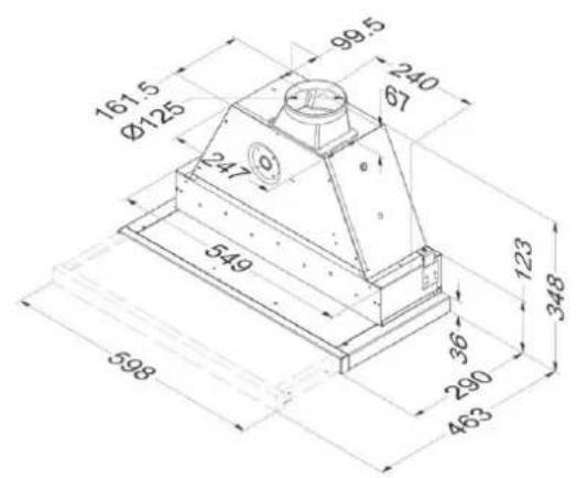
161.5 Ø125 247 549 99.5 240 Ø7 123 348 598 36 290 463691
text_image
104 240.5 19 162 φ150 463 549 123 (250) 405 36 290 463 598692
text_image
161.5 249 849.5 898 99.5 Ø125 67 390 36 280 463 123 348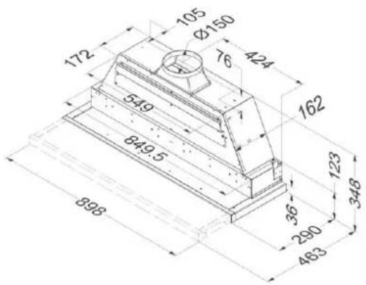
text_image
105 Ø150 76 424 172 549 849.5 162 36 290 463 898 123 348Warrenty certificate NOVY hoods
Naam/Nom/Name/Name: