DW540K - Hammer DEWALT - Free user manual and instructions
Find the device manual for free DW540K DEWALT in PDF.
| Brand | DeWALT |
| Model | DW540K |
| Type | Rotary Hammer Drill |
| Power Supply | 120 V, 60 Hz |
| Power | 1,100 W |
| No Load Speed | 0 – 1,200 rpm |
| Impact Energy | 5.5 J |
| Accessory Retention System | SDS-max |
| Torque Limiting Clutch | Yes, factory-set |
| Electronic Speed and Impact Energy Control | Yes, adjustable from 1 to 5 |
| Mode Selector | Hammer Drilling / Chipping with locked spindle |
| Side Handle | Yes, adjustable to front or rear |
| Depth Gauge | Yes, adjustable |
| LED Indicators | Service indicator (red) and power indicator (green) |
| Soft Start | Yes (models DW541, DW532, DW533, DW545) |
| Weight | 6.5 kg |
| Cable Length | 3 m |
| Warranty | 1 year (extendable) |
| Maintenance | Have repairs and brush replacement done at an authorized service center |
| Included Accessories | Side handle, depth gauge, carrying case |
Frequently Asked Questions - DW540K DEWALT
User questions about DW540K DEWALT
0 question about this device. Answer the ones you know or ask your own.
Ask a new question about this device
Download the instructions for your Hammer in PDF format for free! Find your manual DW540K - DEWALT and take your electronic device back in hand. On this page are published all the documents necessary for the use of your device. DW540K by DEWALT.
USER MANUAL DW540K DEWALT
154728-01 rev 9/10/02 2:23 PM Page 2
DrWALT Industrial Tool Co., 701 East Joppa Road, Baltimore, MD 21286
DW530/DW531/DW532/DW533/DW540/DW541/DW545 Copyright © 2002
Printed in Italy (SEP02-CD-1)
Form No. 154728-01
INSTRUCTION MANUAL GUIDE D'UTILISATION MANUAL DE INSTRUCCIONES
INSTRUCTIVO DE OPERACION, CENTROS DE SERVICIO Y POLIZA DE GARANTIA. ADVERTENCIA: LEASE Este INSTRUCTIVO ANTES DE USAR EL PRODUCTO.
DEWALT®
DW530/DW531/DW532/DW533/DW540/DW541/DW545
Rotary Hammers Perceuses rotatives Rotomartillos

IF YOU HAVE ANY QUESTIONS OR COMMENTS ABOUT THIS OR ANY DeWALT TOOL, CALL US TOLL FREE AT: 1-800-4-DeWALT (1-800-433-9258)
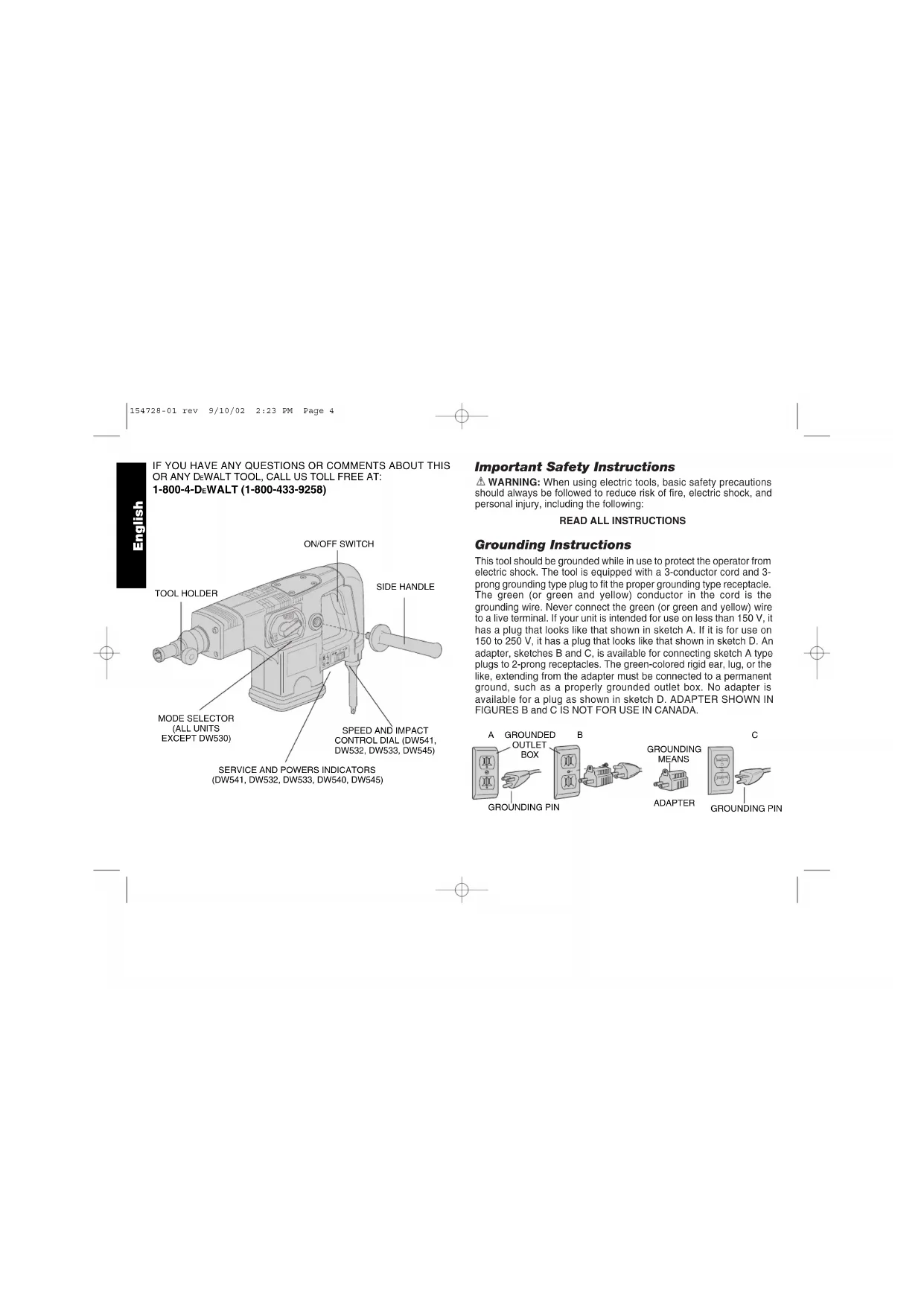
SERVICE AND POWERS INDICATORS (DW541, DW532, DW533, DW540, DW545)
Important Safety Instructions
WARNING: When using electric tools, basic safety precautions should always be followed to reduce risk of fire, electric shock, and personal injury, including the following:
READ ALL INSTRUCTIONS
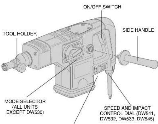
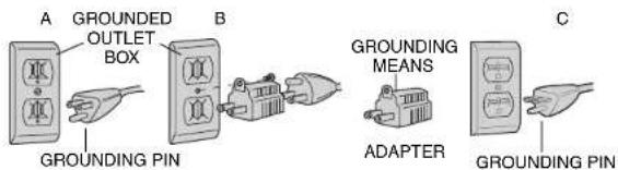
Grounding Instructions
This tool should be grounded while in use to protect the operator from electric shock. The tool is equipped with a 3-conductor cord and 3-prong grounding type plug to fit the proper grounding type receptacle. The green (or green and yellow) conductor in the cord is the grounding wire. Never connect the green (or green and yellow) wire to a live terminal. If your unit is intended for use on less than 150V , it has a plug that looks like that shown in sketch A. If it is for use on 150 to 250V , it has a plug that looks like that shown in sketch D. An adapter, sketches B and C, is available for connecting sketch A type plugs to 2-prong receptacles. The green-colored rigid ear, lug, or the like, extending from the adapter must be connected to a permanent ground, such as a properly grounded outlet box. No adapter is available for a plug as shown in sketch D. ADAPTER SHOWN IN FIGURES B and C IS NOT FOR USE IN CANADA.
Safety Instructions For All Tools
- KEEP WORK AREA CLEAN. Cluttered areas and benches invite injuries.
- CONSIDER WORK AREA ENVIRONMENT. Don't expose power tools to rain. Don't use power tools in damp or wet locations. Keep work area well lit. Do not use tool in presence of flammable liquids or gases.
- GUARD AGAINST ELECTRIC SHOCK. Prevent body contact with grounded surfaces. For example; pipes, radiators, ranges, and refrigerator enclosures.
- KEEP CHILDREN AWAY. Do not let visitors contact tool or extension cord. All visitors should be kept away from work area.
- STORE IDLE TOOLS. When not in use, tools should be stored in dry, and high or locked-up place — out of reach of children.
- DON'T FORCE TOOL. It will do the job better and safer at the rate for which it was intended.
- USE RIGHT TOOL. Don't force small tool or attachment to do the job of a heavy-duty tool. Don't use tool for purpose not intended.
- DRESS PROPERLY. Do not wear loose clothing or jewelry. They can be caught in moving parts. Rubber gloves and non-skid footwear are recommended when working outdoors. Wear protective hair covering to contain long hair.
- USE SAFETY GLASSES. Also use face or dust mask if operation is dusty.
- DON'T ABUSE CORD. Never carry tool by cord or yank it to disconnect from receptacle. Keep cord from heat, oil, and sharp edges.
SECURE WORK. Use clamps or a vise to hold work. It's safer than using your hand and it frees both hands to operate tool. - DON'T OVERREACH. Keep proper footing and balance at all times.
- MAINTAIN TOOLS WITH CARE. Keep tools sharp and clean for better and safer performance. Follow instructions for lubricating
and changing accessories. Inspect tool cords periodically and if damaged, have repaired by authorized service facility. Inspect extension cords periodically and replace if damaged. Keep handles dry, clean, and free from oil and grease.
- DISCONNECT OR LOCK OFF TOOLS when not in use, before servicing, and when changing accessories, such as blades, bits, cutters.
- REMOVE ADJUSTING KEYS AND WRENCHES. Form habit of checking to see that keys and adjusting wrenches are removed from tool before turning it on.
- AVOID UNINTENTIONAL STARTING. Don't carry tool with finger on switch. Be sure switch is off when plugging in.
- EXTENSION CORDS. Make sure your extension cord is in good condition. When using an extension cord, be sure to use one heavy enough to carry the current your product will draw. An undersized cord will cause a drop in line voltage resulting in loss of power and overheating. The following table shows the correct size to use depending on cord length and nameplate ampere rating. If in doubt, use the next heavier gage. The smaller the gage number, the heavier the cord.
Minimum Gage for Cord Sets
Volts Total Length of Cord in Feet
120V 0-25 26-50 51-100 101-150
240V 0-50 51-100 101-200 201-300
Ampere Rating
| More Than | Not | more | AWG | ||
| 0 | - | 6 | 18 | 16 | 14 |
| 6 | - | 10 | 18 | 16 | 14 |
| 10 | - | 12 | 16 | 16 | 14 |
| 12 | - | 16 | 14 | 12 | 12 |
| Not Recommended | |||||
- OUTDOOR USE EXTENSION CORDS. When tool is used outdoors, use only extension cords intended for use outdoors and so marked.
- STAY ALERT. Watch what you are doing. Use common sense. Do
not operate tool when you are tired.
- CHECK DAMAGED PARTS. Before further use of the tool, a guard or other part that is damaged should be carefully checked to determine that it will operate properly and perform its intended function. Check for alignment of moving parts, binding of moving parts, breakage of parts, mounting, and any other conditions that may affect its operation. A guard or other part that is damaged should be properly repaired or replaced by an authorized service center unless otherwise indicated elsewhere in this instruction manual. Have defective switches replaced by authorized service center. Do not use tool if switch does not turn it on and off.
Additional Safety Instructions for Rotary Hammers
- WEAR SAFETY GOGGLES or other eye protection.
- WEAR EAR PROTECTORS when hammering for extended periods.
- ALWAYS USE THE SIDE HANDLE supplied with the tool. Keep a firm grip on the hammer when it is operating.
- DONT OVERREACH. Maintain a firm, balanced working stance. When necessary, use only properly positioned, safe platforms, ladders and scaffolds, to do the job safely.
- Hammer bits and tools get hot in operation. Wear gloves when touching them.
- CAUTION: When drilling or driving into walls, floors or wherever "live" electrical wires may be encountered, DO NOT TOUCH ANY FRONT METAL PARTS OF THE TOOL! Hold the tool only by the plastic handle to prevent shock if you drill or drive into a "live" wire.
SAVE THESE INSTRUCTIONS FOR FUTURE USE
Motor
Your tool is powered by a D-WALT built motor. Be sure your power supply agrees with nameplate marking.
Voltage decrease of more than 10% will cause loss of power and overheating. All DeWALT tools are factory tested; if this tool does not operate, check the power supply.
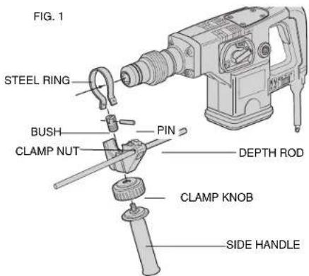
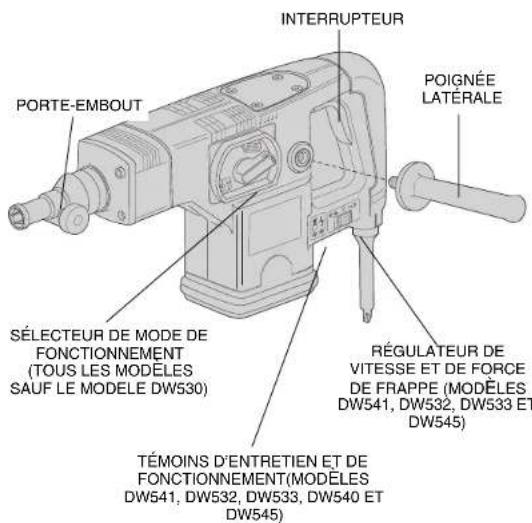
Side Handle and Depth Rod
For operating convenience, the side handle can be installed in front or rear positions. Always operate the tool with the side handle properly assembled.
TO MOUNT IN FRONT POSITION (FIG. 1)
- Unscrew the side handle and disassemble the side handle clamp.
- Snap the steel ring over the collar behind the tool holder. Squeeze both ends together, mount the bush and insert the pin.
- Place the side handle clamp and screw on the clamp knob. Do not tighten.
- Insert adjustable depth rod into hole.
- Screw the side handle into the clamp knob and tighten it.
- Rotate the side handle mounting assembly to the desired position. For drilling horizontally with a heavy drill bit, place the side handle assembly at an angle of approximately 20^ for optimum control.
- Lock the side handle mounting assembly in place by tightening the clamp knob.
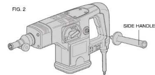
TO MOUNT IN REAR POSITION (FIG. 2)
- Unscrew the side handle and remove it from the front position. Leave the side handle mounting assembly in front position so that the depth adjustment rod can still be used.
- Screw the side handle directly into one of the rear side handle positions on either side of the tool.

TO ADJUST THE DEPTH ROD
- Loosen clamp nut and insert bit into tool holder.
- Push drill bit into a surface and adjust rod to desired depth of hole (distance between bit tip and depth rod tip).
- Tighten clamp nut.
NOTE: This adjustment can be made with or without side handle in place.
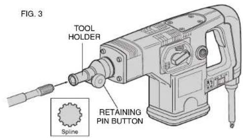
Inserting and Removing Spline Drive Accessories
FIG.3: (DW531, DW530, DW532, DW533)
TURN OFF TOOL AND DISCONNECT FROM POWER SUPPLY.
- Unlock the tool holder by pushing the retaining pin button and holding it in.
- Insert the bit shank into the tool holder as far as it will go.
- Release the retaining pin button.
- Pull on the bit to check if it is properly locked.
- To remove a bit unlock the tool holder as described above.
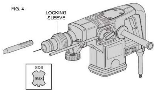
Inserting and Removing SDS-max™ Accessories
FIG.4: (DW541, DW540 AND DW545)
TURN OFF TOOL AND DISCONNECT FROM POWER SUPPLY.
- Pull back the tool holder locking sleeve and insert the bit shank.
- Turn the bit slightly until the sleeve snaps back in position.
- Pull on the bit to check if it is properly locked. The hammering function requires the bit to be able to move axially several centimeters when locked in the tool holder.
- To remove bit, pull back the tool holder locking sleeve and pull the bit out of the tool holder.
Soft Start Feature (DW541, DW532, DW533, DW545)
The soft start feature allows you to build up speed slowly, thus preventing the drill bit from walking off the intended hole position when starting. The soft start feature also reduces the immediate torque reaction transmitted to the gearing and the operator if the hammer is started with the drill bit in an existing hole.
Torque Limiting Clutch
All rotary hammers are equipped with a torque limiting clutch that reduces the maximum torque reaction transmitted to the operator in the case of a jamming drill bit. This feature also prevents the gearing and motor from stalling. The torque limiting clutch has been factory set and cannot be adjusted.
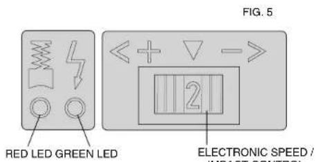
Electronic Speed and Impact Control (DW541, DW532, DW533, DW545)
(Fig. 5) The electronic speed and impact control allows the use of smaller drill bits without the risk of bit breakage, drilling into light and brittle materials without shattering, and optimal tool control for precise chiseling. To set the control dial: Turn the dial to the desired level. The higher the number, the greater the speed and impact energy. With dial settings from "1" to "5" (full power) the tool is extremely flexible and adaptable for many different applications. The required setting depends on the bit size and hardness of material being drilled.
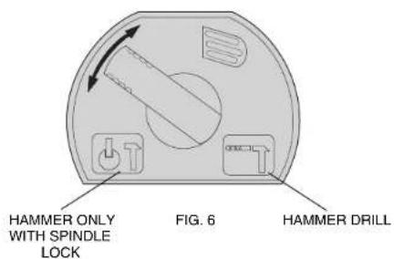
Mode Selector
(Fig. 6) Your rotary hammer (all units except DW530) can be used in two operating modes: Hammer drilling (simultaneous rotating and impacting for all concrete and masonry drilling operations) and Hammering only with spindle lock (impacting only- for light chipping, chiseling, and demolition applications. The chisel can be locked into 8 different positions.
NOTE: Also in this mode, the hammer can also be used as a lever to free a jammed drill bit.
To select the required operating mode, rotate the selector lever over the safety lock until it covers the symbol.
SERVICE AND POWER INDICATOR LEDs (DW541, DW532, DW533, DW545)
(Fig. 5) The RED service indicator LED lights up when the carbon brushes are nearly worn out to indicate that the tool needs servicing. After approximately 8 hours of use the motor will automatically be shut off. Take the tool to a DzWALT service location for routine inspection and maintenance.
The GREEN power-ON indicator LED lights up when the tool is switched ON. If the indicator LED is lit but the tool does not start, this indicates a motor related problem. If the indicator LED does not light up and the tool does not start, this indicates an ON/OFF switch or cord related problem.
DRILLING WITH A SOLID BIT
- Set the speed and impact control dial (DW541, DW532, DW533, DW545).
- Set the model selector to the "hammer drilling" position (for all units except DW530).
- Insert the appropriate drill bit.
- Fit and adjust the side handle.
- If necessary, set the drilling depth rod.

- Mark the spot where the hole is to be drilled.
- Place the drill bit on the spot and press the ON/OFF switch.
- Push with only enough force until hammer beats smoothly. The hammer only needs enough pressure or force to engage the mechanism. Pushing harder will not make the hammer drill faster.
- To stop the tool, release the ON/OFF switch. Always turn the tool OFF when work is finished and before unplugging.
DRILLING WITH A CORE BIT
- Turn the speed and impact control dial to the maximum torque position. (DW541, DW532, DW533 DW545)
- Set the model selector to the "hammer drilling" position (for all units except DW530).
- Fit and adjust the side handle.
- Assemble the centering bit and adapter shank into core bit.
- Place the centering bit on the spot and press the ON/OFF switch.
NOTE: Some core drills require the removal of centering bit after about 1cm of penetration. If so, remove and continue drilling. - When drilling through a structure thicker than the depth of the core bit, break away the round cylinder of concrete or core inside the bit at regular intervals. To avoid unwanted breaking away of concrete around the hole, first drill a hole the diameter of the centering bit completely through the structure. Then drill the cored hole halfway from each side.
- To stop the tool, release the ON/OFF switch. Always turn the tool OFF when work is finished and before unplugging.
CHIPPING AND CHISELING
- Set the model selector to the "hammering only with spindle lock" position on all models except DW530 in which it is not necessary.
- Set the impact control dial to desired impact energy.
-
Insert the appropriate chisel and rotate it by hand to lock it into the desired position. For spline units, use a 3/4'' hex × 21/32'' round insert tool and for SDS Max models use SDS Max insert tools.
-
Fit and adjust the side handle.
- Press the ON/OFF switch and start working.
- Push with enough force to keep bit from bouncing only. Pushing harder will not increase chipping speed.
- To stop the tool, release the ON/OFF switch. Always turn the tool OFF when work is finished and before unplugging.
Accessories
Recommended accessories for use with your tool are available at extra cost from your distributor or local service center.
CAUTION: The use of any non-recommended accessory may be hazardous.
Repairs
To assure product SAFETY and RELIABILITY, repairs, maintenance and adjustment (including brush inspection and replacement) should be performed by authorized service centers or other qualified service organizations, always using identical replacement parts.
Full Warranty
D-WALT heavy duty industrial tools are warranted for one year from date of purchase. We will repair, without charge, any defects due to faulty materials or workmanship. For warranty repair information, call 1-800-4-D-WALT. This warranty does not apply to accessories or damage caused where repairs have been made or attempted by others. This warranty gives you specific legal rights and you may have other rights which vary in certain states or provinces.
In addition to the warranty, DeWALT tools are covered by our:
30 DAY NO RISK SATISFACTION GUARANTEE
If you are not completely satisfied with the performance of your DeWALT heavy duty industrial tool, simply return it to the participating seller within 30 days for a full refund. Please return the complete unit, transportation prepaid. Proof of purchase may be required.
POUR TOUT RENSEIGNEMENT SUPPLEMENTaire SUR CET OUTIL OU TOUT AUTRE OUTIL DEWALT, COMPOSER SANS FRAIS LE NUMERO: 18004-DEWALT (1800433-9258)
(DW530, DW531, DW532, DW540, DW541)
FIGURA 4: (DW540, DW541 Y DW545)
APAGUE LA HERRAMIENTA Y DESCONECTELA DE LA TOMA DE CORRIENTE.
BOSQUES DE CIDROS ACCESO RADIATAS NO.42
COL. BOSQUES DE LAS LOMAS
05120 MEXICO, D.F.
TEL.326-7100
Para增值服务yventasconsulte
"HERRAMIENTAS ELECTRICAS"