
OWM3000ST - Projector Accessory OPTOMA - Free user manual and instructions
Find the device manual for free OWM3000ST OPTOMA in PDF.

| Product Type | Wall Mount for Projector |
| Brand | Optoma |
| Model | OWM3000ST |
| Net Weight | 6.8 kg (15 lb) |
| Maximum Load Capacity | 7.5 kg (16.5 lb) with safety factor 4 |
| Extension Length | 495 mm to 1250 mm (19 to 49 in) |
| Vertical Tilt Adjustment | ±5° |
| Horizontal Rotation Adjustment | ±5° |
| Horizontal Roll Adjustment | ±5° |
| Material | Steel (estimated) |
| Color | Black (estimated) |
| Compatible Wall Types | Concrete, drywall, calcium silicate board |
| Included Fasteners | M6x55 screws, 10 mm anchor plugs, L5 and L3 Allen keys, M4x8, M6x15 screws, etc. |
| Installation Steps | Wall fixing, arm assembly, projector mounting, image adjustments |
| Projector Compatibility | Certain Optoma models (EH415ST, W305ST, X308ST, etc.) - see list |
| Certification | TÜV |
| Maintenance and Cleaning | Clean with a soft, dry cloth |
| Number of People Required for Installation | At least 2 people |
| Intended Use | Wall mounting projector with precise adjustments |
Frequently Asked Questions - OWM3000ST OPTOMA
User questions about OWM3000ST OPTOMA
0 question about this device. Answer the ones you know or ask your own.
Ask a new question about this device
Download the instructions for your Projector Accessory in PDF format for free! Find your manual OWM3000ST - OPTOMA and take your electronic device back in hand. On this page are published all the documents necessary for the use of your device. OWM3000ST by OPTOMA.
USER MANUAL OWM3000ST OPTOMA
natural_image
Technical line drawing of a robotic arm assembly (no text or symbols)Contents
English...... 2-10
Français......11-19
Deutsch......20-28
Español......29-38
Română......39-48
Safety
Read these instructions carefully before installing your equipment
• Install the mount in suitable location using fixings which are appropriate for the wall material and structure
- Consult a qualified builder if you are in any doubt as to the structural integrity of the wall
• Use all available fixing points
• DO NOT attempt to alter or modify any part of the wall mount or its attachments
• DO NOT use if any parts are broken or appear to be damaged.
• Tighten all bolts and fixings securely
• Only use fixing provided with this bracket
• DO NOT mount your projector near to sources of heat of moisture
• Always have minimum of two persons to install the projector and the mount
Package Overview

natural_image
Technical line drawing of a mechanical assembly with no visible text or symbolsSupport Arm x 1

Projector Mounting Plate x 1

Wall Plate Cover x 1

Wall Plate x 1

Wall Cover x 1

Mounting arms x 4
Fixing Kit
| NO | diagrammatic presentation | designation | quantity |
| A | Screw(M6x55) | 5 | |
| B | Φ10mm Anchor Bolt | 5 | |
| C | L5 Allen Wrench | 1 | |
| D | L3 Allen Wrench | 1 | |
| E | Screw(M4x8) | 4 | |
| F | Screw(M6x15) | 4 | |
| G | Connecting Screw M4 | 4 | |
| H | Screw(M3x10) | 4 | |
| I | Screw(M5x12) | 4 | |
| J | Screw(M5x25) | 4 | |
| K | Nut M5 | 4 | |
| L | Plastic Spacer (8.0) | 4 |
Step 1: Attach the wall plate to the wall

● The bracket is suitable for concrete wall mounting or wooden stud wall or calcium silicate board.
- For concrete wall mounting, thickness of the wall must be not less than 4" (100mm). Anchor bolt and screw (M6x55) are needed to be used for concrete wall installation.
- For wood stud wall mounting, the minimum size of the wall should not be less than 20x12 inch. The thickness of the wall must be not less than 3" (76.2mm). If there is a gypsum board on the surface of wood stud wall, the thickness of gypsum board should not be bigger than 3/8 inch .Only screw (M6x55) is needed to be used for the installation
● For calcium silicate board mounting, screws M6x55 must be attached to the stud and securely fastened.
Note: If the thickness of wall is not strong enough, reinforce it sufficiently before installation.

- Insert screw A (M6x55) from the fixing kit, tighten with a L5 Allen Wrench from fixing kit.
Step 2: Attach the projector mount to the wall plate

Loosen the screws with L3 Allen Wrench, pull out the telescopic arm around 4" (100mm) and make power cable & signal cables go through the telescopic arm.

The cables can go through the wall plate by three ways as shown in the pictures. Then, tighten the screw F after locating the projector position.
- Insert Screw F (M6x15) from the fixing kit, tighten with a L5 Allen Wrench from fixing kit.
Step 3: Attach the projector to mount plate and to the mount
A. Using the custom mounting holes to connect the projector

| Models | ID | Mounting Hole Group | Models | ID | Mounting Hole Group |
| EH415ST |  | A | W460ST, EH460ST |  | F |
| W305ST, W303ST, W305ST |  | B | ZX310ST, ZW310ST |  | E |
| X308ST, W308ST, X318ST, W318ST |  | B | ZU500TST |  | B |
| EH200ST, X316ST, W316ST |  | C | W515ST, WU515ST, WU515TST, EH515ST, EH515ST |  | D |
| 4K550ST |  | G | Lamp based models and laser based models* |  | E |
Note:* These models are ultra short throw projectors.
Attach the mounting plate to the projector

● Loosen the screw on the mount and pre-tighten the projector on the mount.
- If the projector feet on the bottom of the projector prevent the mounting plate sitting flush, then connecting screw M4( marked as G) should be used.
B. Using mounting arms and universal slots to connect the projector Firstly, fix the mounting arms on the mounting plate

Note: To show a clear picture of how to fix the mounting arms on the mounting plate, the plate is turned upside down, which means the hooks are down, seen from the view of the above two pictures.
Secondly, then attach the whole mounting plate to the projector

| Without Connecting Screw M4 | Select E(M4x8) /H(M3x10) |
| With Connecting Screw M4 | Select E(M4x8) only |
- According to the diameter of the mounting holes on the bottom of the projector, please select right size of screws, as shown in the above table. If the projector feet prevent the plate sitting flush, connecting screw M4 should be used, which can only work with screw M4x8.

Insert screws M5x25, marked as J, into the slots of the mounting arms, and fix the mounting plate to the projector.
- If the diameter of the mounting holes on the bottom of the projector is M5, then M5x25 should be used. If projector feet prevent the plate sitting flush, spacer (L) should be used
Thirdly, attach the projector to the mount.

natural_image
Technical illustration of a mechanical assembly with a component, showing a shaft, housing, and directional arrows (no text or symbols)C. Using universal slots to connect the projector

| Without Connecting Screw M4 | Select E(M4x8) /H(M3x10) /I(M5x12) |
| With Connecting Screw M4 | Select E(M4x8) only |
- If universal slots on the mounting plate can cover all the mounting holes of the projector, please connect the plate directly to the projector with right size screws, as shown on the above table.
Attach the projector to the mount.

natural_image
Technical line drawing of a mechanical assembly with an arrow indicating direction (no text or symbols present)Step 4: Adjusting the image horizontally
Slide the mount plate


flowchart
graph TD
    A1["Component A"] -->|A| B1["Component B"]
    B1 -->|B| C1["Component C"]
    style A fill:#f9f,stroke:#333
    style B fill:#f9f,stroke:#333
    style C fill:#f9f,stroke:#333
Screen Adjustment Direction

natural_image
Technical line drawing of a mechanical assembly with mounting base and bracket (no text or symbols)Tighten the screws

natural_image
Technical line drawing of a mechanical assembly with a base and control panel (no text or symbols)Power cable
Signal cable
Connect power cable and other signal cable to the projector
Step 5: Adjusting the image size

Note: To make adjustments to meet your demands, screws must be loosened in a specific order, as shown in the above Fig① ,Fig② . (When the length of inside arm 895mm do not meet your demands, then you should loose the screws on the outside arm to adjust the middle arm. Under this circumstance, the number read on the middle arm is correct).
Step 6: Adjusting the image height

● Loosen the screws slightly to adjust the projector to the required position.
Step 7: Adjusting the vertical tilt

Vertical tilt Knob
Step 8: Adjusting the horizontal roll

natural_image
Mechanical assembly diagram showing a rotating component with labeled parts A and B (no text or symbols beyond labels)Horizontal Roll Knob

flowchart
graph TD
    A["Device 1"] -->|A| C((Circular Ring))
    B["Device 2"] -->|B| D((Circular Ring))
    C <--> E["Square"]
    D <--> F["Square"]
Screen Adjustment Direction
Step 9: Adjusting the horizontal rotation

natural_image
Mechanical assembly diagram showing a rotating component with labeled parts A and B (no text or symbols beyond labels)Horizontal Rotation Knob

flowchart
graph TD
    A["Component A"] -->|Rotating Circle| B["Component B"]
    B -->|Rotating Square| A
    style A fill:#f9f,stroke:#333
    style B fill:#bbf,stroke:#333
Screen Adjustment Direction
Step 10: Using the decorative covers

Note: When all adjustments are done, the wall plate covers can be used to cover the blank area on the top of wall plate. The number of wall plate cover used depends on the size of blank area. But the wall cover must be used in an specific order as the picture on left shows. Finally, put the wall cover on.
Product Information
| Net Weight | 6.8kg(15lb) |
| Weight Capacity | 7.5kg(16.5lb)* |
| Extendable Length | 495mm-1250mm(19-49in) |
| Adjustment Angle | Vertical tilt, Horizontal roll, Horizontal rotation ± 5^ |
Note: * This mount is TUV certified. Safety factor is 4.
Specification

OWM3000
Support mural
courte focale

natural_image
Technical line drawing of a robotic arm assembly (no text or symbols)Sécurité
natural_image
Technical illustration of a mechanical assembly with a component, showing a shaft, housing, and directional arrows (no text or symbols)natural_image
Technical line drawing of a mechanical assembly with an arrow indicating direction (no text or symbols present)natural_image
Technical line drawing of a mechanical assembly with mounting base and bracket (no text or symbols)Serrez les vis

natural_image
Technical line drawing of a robotic arm mounted on a base with control panel (no text or symbols)natural_image
Mechanical assembly diagram showing a rotating component with labeled parts A and B (no text or symbols beyond labels)natural_image
Mechanical assembly diagram showing a rotating component with labeled points A and B (no text or symbols beyond labels)Bouton de rotation horizontale

flowchart
graph TD
    A["Component A"] -->|A| B["Component B"]
    B -->|B| A
    style A fill:#f9f,stroke:#333
    style B fill:#bbf,stroke:#333
natural_image
Technical line drawing of a robotic arm assembly (no text or symbols)Sicherheit
natural_image
Technical line drawing of a mechanical assembly with rods and supports (no text or symbols)Support Arm x 1
natural_image
Technical illustration of a mechanical assembly with a component, showing a shaft, housing, and directional arrows (no text or symbols)natural_image
Technical line drawing of a mechanical assembly with an arrow indicating direction (no text or symbols present)natural_image
Technical line drawing of a mechanical assembly with mounting base and bracket (no text or symbols)Schrauben anziehen

natural_image
Technical line drawing of a mechanical assembly with a base and control panel (no text or symbols)natural_image
Mechanical assembly diagram showing a rotating component with labeled parts A and B (no text or symbols beyond labels)Horizontaler Roll Knopf

flowchart
graph TD
    A["Device 1"] -->|A| C((Circular Ring))
    B["Device 2"] -->|B| D((Circular Ring))
    C <--> E["Square"]
    D <--> F["Square"]
natural_image
Mechanical assembly diagram showing a rotating component with labeled parts A and B (no text or symbols beyond labels)Horizontaler Rotations Knopf

flowchart
graph TD
    A["Component A"] -->|A| B["Component B"]
    B -->|B| A
    style A fill:#f9f,stroke:#333
    style B fill:#bbf,stroke:#333
natural_image
Technical line drawing of a robotic arm assembly (no text or symbols)Seguridad
natural_image
Technical line drawing of a mechanical component with two rectangular parts mounted on a frame, no text or symbols present.

natural_image
Diagram of a screwdriver positioned above a vertical line with scattered cross marks (no text or symbols)natural_image
Technical illustration of a mechanical assembly with a component, showing a shaft, housing, and a rotating arrow (no text or symbols)natural_image
Technical line drawing of a mechanical assembly with an arrow indicating direction (no text or symbols present)natural_image
Technical line drawing of a mechanical assembly with mounting bracket and base, showing internal components and motion direction (no text or symbols)natural_image
Technical line drawing of a mechanical assembly with a bracket and base unit, showing internal components (no text or symbols)natural_image
Technical line drawing of two mechanical components mounted on a vertical pole (no text or symbols)
flowchart
graph TD
    A["A"] -->|↑| B["B"]
    B -->|↓| A
natural_image
Mechanical assembly diagram showing a rotating component with labeled parts A and B (no text or symbols beyond labels)Perilla de rodillo horizontal

flowchart
graph TD
    A["Device A"] -->|A| C((Circular Component))
    C -->|B| B["Device B"]
    style A fill:#f9f,stroke:#333
    style B fill:#bbf,stroke:#333
natural_image
Mechanical assembly diagram showing a rotating component with labeled parts A and B (no text or symbols beyond labels)

natural_image
Mechanical assembly diagram showing a robotic arm with directional arrows indicating motion (no text or symbols present)natural_image
Technical line drawing of a mechanical assembly with no visible text or symbolsOWM3000
Montare projector
cu aruncare scurtă

natural_image
Technical line drawing of a robotic arm assembly (no text or symbols)Siguranță
| Modele | ID | Grup de găuri de montare | Modele | ID | Grup de găuri de montare | |
| EH415ST |  | A | W460ST, EH460ST |  | F | |
| W305ST, W303ST, W305ST |  | B | ZX310ST, ZW310ST |  | E | |
| X308ST, W308ST, X318ST, W318ST |  | B | ZU500TST |  | B | |
| EH200ST, X316ST, W316ST |  | C | W515ST, WU515ST, WU515TST, EH515ST, EH515ST |  | D | |
| 4K550ST |  | G | Modele bazate pe lămpi și modele cu laser* |  | E | |
natural_image
Technical illustration of a mechanical assembly with a component, showing a shaft, housing, and a rotating arrow (no text or symbols)natural_image
Technical line drawing of a mechanical assembly with an arrow indicating direction (no text or symbols present)natural_image
Technical line drawing of a mechanical assembly with mounting base and bracket (no text or symbols)natural_image
Technical line drawing of a mechanical assembly with a base and control panel (no text or symbols)natural_image
Mechanical assembly diagram showing a rotating component with labeled parts A and B (no text or symbols beyond labels)Buton rotativ orizontal

flowchart
graph TD
    A["Device 1"] -->|A| C((Circular Ring))
    B["Device 2"] -->|B| D((Circular Ring))
    C <--> E["Square"]
    D <--> F["Square"]
natural_image
Mechanical assembly diagram showing a rotating component with labeled parts A and B (no text or symbols beyond labels)Buton rotativ orizontal

flowchart
graph TD
    A["Component A"] -->|A| B["Component B"]
    B -->|B| A
    style A fill:#f9f,stroke:#333
    style B fill:#bbf,stroke:#333
natural_image
Technical line drawing of a mechanical assembly with no visible text or symbols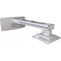

- Contents
- Safety
- Package Overview
- Step 1: Attach the wall plate to the wall
- Step 2: Attach the projector mount to the wall plate
- Step 3: Attach the projector to mount plate and to the mount
- Using the custom mounting holes to connect the projector
- Attach the mounting plate to the projector
- Using mounting arms and universal slots to connect the projector Firstly, fix the mounting arms on the mounting plate
- Secondly, then attach the whole mounting plate to the projector
- Thirdly, attach the projector to the mount.
- Using universal slots to connect the projector
- Step 5: Adjusting the image size
- Step 6: Adjusting the image height
- Step 7: Adjusting the vertical tilt
- Step 8: Adjusting the horizontal roll
- Step 9: Adjusting the horizontal rotation
- Step 10: Using the decorative covers
- Product Information
- OWM3000
- Support mural
- courte focale
- Sécurité
- Sicherheit
- Seguridad
- Montare projector
- cu aruncare scurtă
- Siguranță
Brand : OPTOMA
Model : OWM3000ST
Category : Projector Accessory