
OWM3000 - Projector Accessory OPTOMA - Free user manual and instructions
Find the device manual for free OWM3000 OPTOMA in PDF.

| Product Type | Ultra short throw projector mount |
| Brand | OPTOMA |
| Model | OWM3000 |
| Net weight | 5.0 kg |
| Maximum weight capacity | 15.0 kg |
| Extendable length | 325 mm - 740 mm |
| Vertical tilt angle | ±5° |
| Horizontal roll angle | ±5° |
| Horizontal rotation angle | ±5° |
| Material | Steel and plastic |
| Color | Black |
| Wall mounting | Yes |
| Mounting type | Wall |
| Package contents | Mount arm, projector mounting plate, cover for wall plate, wall plate, wall cover, mounting kit (5 M6x55 screws, 5 anchor bolts, 1 Allen key L5, 1 Allen key L3, 4 M4x8 screws, 4 M6x15 screws) |
| Safety instructions | Read carefully before installation |
| Number of people required for installation | 2 |
| Warranty | 2 years |
| Maintenance and cleaning | Clean with a soft, dry cloth. Do not use abrasive products. |
| Spare parts and repairability | Contact OPTOMA customer service for spare parts. Do not modify parts. |
| General information | Mount designed for ultra short throw projectors. Wall installation required. Follow the steps in the manual. |
Frequently Asked Questions - OWM3000 OPTOMA
User questions about OWM3000 OPTOMA
0 question about this device. Answer the ones you know or ask your own.
Ask a new question about this device
Download the instructions for your Projector Accessory in PDF format for free! Find your manual OWM3000 - OPTOMA and take your electronic device back in hand. On this page are published all the documents necessary for the use of your device. OWM3000 by OPTOMA.
USER MANUAL OWM3000 OPTOMA
natural_image
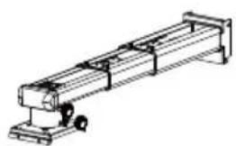
Technical line drawing of a mechanical assembly with a bracket and base (no text or symbols)User manual
Contents
English.....2-6
Deutsch......7-11
Français......12-16
Italiano......17-21
Safety
Read these instructions carefully before installing your equipment
• Install the mount in a suitable location using fixings which are appropriate for the wall material and structure
- Consult a qualified builder if you are in any doubt as to the structural integrity of the wall
• Use all available fixing points
• DO NOT attempt to alter or modify any part of the wall mount or its attachments
• DO NO use if any parts are broken or appear to be damaged
• Tighten all bolts and fixings securely
• Only use fixing provided with this bracket
• DO NOT mount your projector near to sources of heat or moisture
• Always have a minimum of two persons to install the projector and the mount
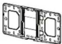
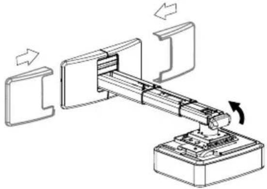
Package Overview
natural_image
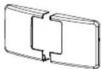
Technical line drawing of a mechanical assembly with no visible text or symbolsSupport Arm x 1
Projector Mounting Plate x 1
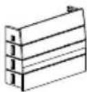
Wall Plate Cover x 1
Wall Plate x 1
Wall Cover x 1
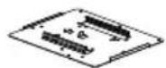
Fixing Kit
| NO | diagrammatic presentation | Specification | quantity |
| A | Screw (M6x55) | 5 | |
| B | Anchor bolt | 5 | |
| C | L5 Allen key | 1 | |
| D | L3 Allen key | 1 | |
| E | Screw (M4x8) | 4 | |
| F | Screw (M6x15) | 4 |
Step 1: Attach the wall plate to the wall
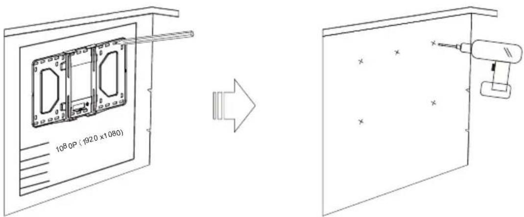
- If the board has been installed, please align the center line of the projector lens on the installation chart with that of the screen or board to the locate the place of the mount period.
- For concrete wall mounting, thickness of the wall must be not less than 4" (100mm). Anchor bolt and screw (M6x55) are needed to be used for concrete wall installation.
- For Dry-wall mounting, thickness of the dry-wall must be not less than 4.5" (114mm). Only screw (M6x55) is needed to be used for installation, and gypsum board thickness less than 0.59" (15mm).
Note: If the thickness of wall is not strong enough, reinforce it sufficiently before installation.
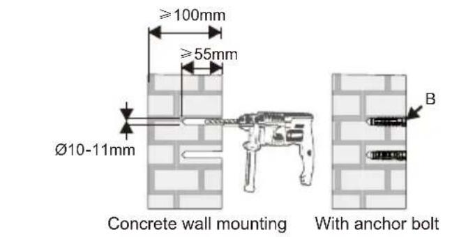
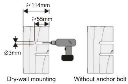
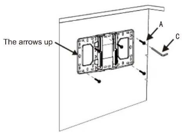
- Insert Screw A (M6x55) from the fixing kit, tighten with a L5 Allen Key from fixing kit.
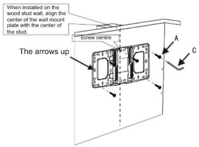
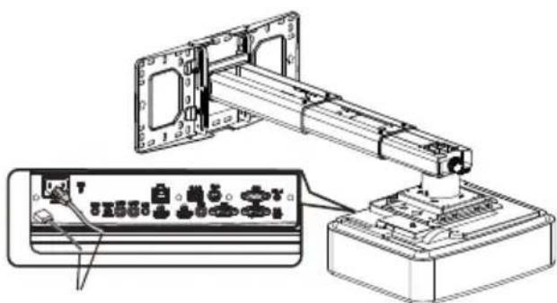
Step 2: Attach the projector mount to the wall plate
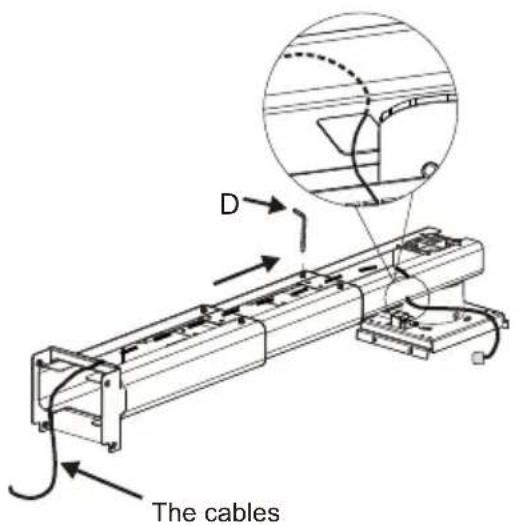
Loosen the screws with L3 allen wrench, pull out the support arm around 4" (100mm) and make power cable & signal cables go through the support arm.
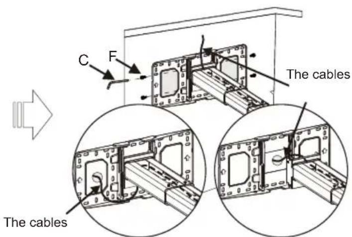
The cables can go through the wall plate by three ways as shown in the pictures. Then, tighten the screw F after locating the position of the projector mount period.
- Insert Screw F (M6x15) from the fixing kit, tighten with a L5 Allen Key from fixing kit.
Step 3: Attach the projector to mount plate and to the mount
● Loosen the screw on the mount and pre-tighten the projector on the mount.
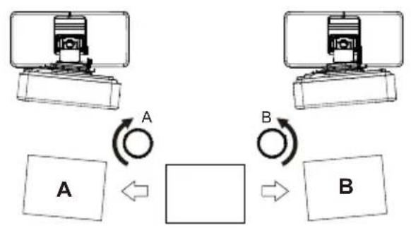
Step 4: Adjusting the image horizontally
Step 5: Adjusting the image size
Note: To make adjustments to meet your demands, screws must be loosened in a specific order, as shown in the above Fig① ,Fig②. (When the length of inside arm 555mm do not meet your demands, then you should loose the screws on the outside arm to adjust the middle arm. Under this circumstance, the number read on the middle arm is correct).
Step 6: Adjusting the image height
● Loosen the screws slightly to adjust the projector to the required position.
Step 7: Adjusting the vertical tilt
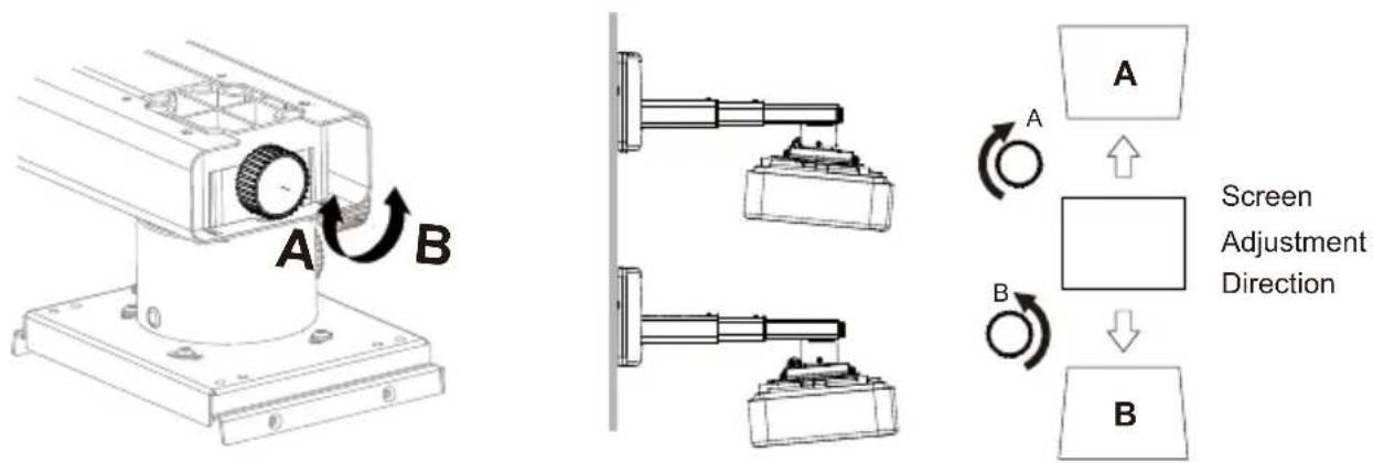
Vertical tilt Knob
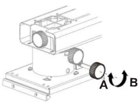
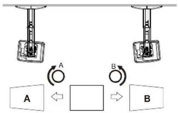
Step 8: Adjusting the horizontal roll
natural_image
Mechanical assembly diagram showing a rotating component with labeled parts A and B (no text or symbols beyond labels)Horizontal Roll Knob
flowchart
graph TD
    A["Device A"] -->|A| Loop1((Loop))
    Loop1 -->|B| Box1((Box))
    Box1 -->|B| Box2((Box))
    Box1 <--> Box2
Screen Adjustment Direction
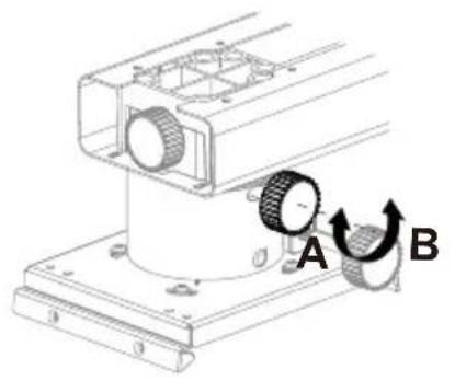
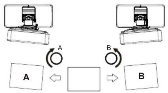
Step 9: Adjusting the horizontal rotation
natural_image
Mechanical assembly diagram showing a rotating component with labeled points A and B (no text or symbols beyond labels)Horizontal Rotation Knob
flowchart
graph TD
    A["Component A"] -->|A| B["Component B"]
    B -->|B| A
    style A fill:#f9f,stroke:#333
    style B fill:#bbf,stroke:#333
Screen Adjustment Direction
Step 10: Using the decorative covers
Wall plate covers
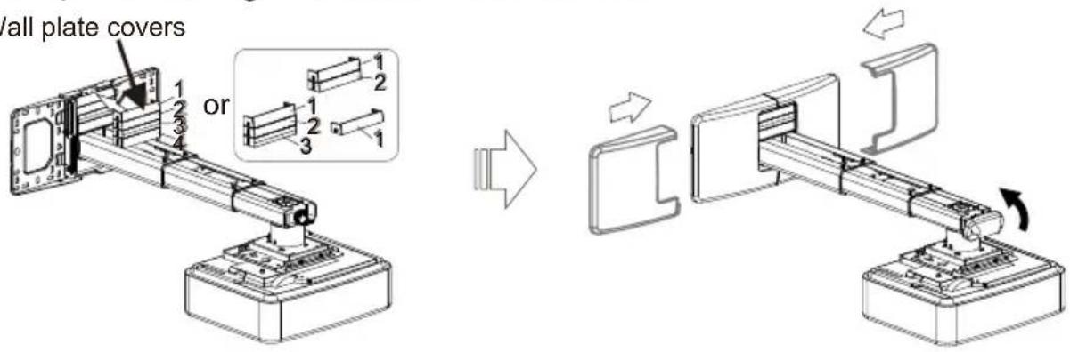
Note: When all adjustments are done, the wall plate covers can be used to cover the blank area on the top of wall plate. The number of wall plate cover used depends on the size of blank area. But the wall cover must be used in an specific order as the picture on left shows. Finally, put the wall cover on.
Product Information
| Net Weight | 5.0kg(11lb) |
| Weight Capacity | 15.0kg(33lb) |
| Extendable Length | 325mm-740mm(12.8-29in) |
| Adjustment Angle | Verticaltilt, Horizontal roll, Horizontal rotation ± 5° |
natural_image
Technical line drawing of a mechanical assembly with a bracket and base platform (no text or symbols)Gebrauchsanleitung
Sicherheit
natural_image
Technical line drawing of a mechanical assembly with no visible text or symbolsStützarm x 1
natural_image
Mechanical assembly diagram showing a rotating component with labeled parts A and B (no text or symbols beyond labels)natural_image
Mechanical assembly diagram showing a rotating component with labeled parts A and B (no text or symbols beyond labels)
natural_image
Mechanical assembly diagram showing a robotic arm with directional arrows indicating motion (no text or symbols)natural_image
Technical line drawing of a mechanical assembly with a bracket and base (no text or symbols)Sécurité
natural_image
Technical line drawing of a mechanical assembly with no visible text or symbolsBras du Support x 1
natural_image
Mechanical assembly diagram showing a rotating component with labeled parts A and B (no text or symbols beyond labels)natural_image
Mechanical assembly diagram showing a rotating component with labeled points A and B (no text or symbols beyond labels)natural_image
Technical line drawing of a mechanical assembly with a bracket and base (no text or symbols)Sicurezza
natural_image
Technical line drawing of a mechanical assembly with no visible text or symbolsSupporto x 1
natural_image
Technical line drawing of a mechanical assembly with mounting base and housing (no text or symbols)Serrare le viti
natural_image
Mechanical assembly diagram showing a rotating component with labeled parts A and B (no text or symbols beyond labels)rollio orizzontale
flowchart
graph TD
    A["Device A"] -->|A| Loop1["Loop"]
    B["Device B"] -->|B| Loop2["Loop"]
    Loop1 -->|A| Box1["Box"]
    Loop2 -->|B| Box2["Box"]
natural_image
Mechanical assembly diagram showing a rotating component with labeled points A and B (no text or symbols beyond labels)

Brand : OPTOMA
Model : OWM3000
Category : Projector Accessory