
SCCC6455 - Surveillance Camera SAMSUNG - Free user manual and instructions
Find the device manual for free SCCC6455 SAMSUNG in PDF.
| Product Type | Surveillance Camera |
| Brand | Samsung |
| Model | SCCC6455 |
| Resolution | 600 lines high resolution |
| Optical Zoom | x43 |
| Digital Zoom | Up to x688 (43 x 16) |
| Main Functions | WDR, Auto Day/Night, white balance, backlight compensation, auto focus, pan/tilt, privacy zones, motion detection |
| Power Supply | 24 V AC, 1.5 A |
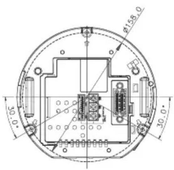
| Dimensions | Ø158 mm (diameter) |
| Operating Temperature | -10 °C to 50 °C |
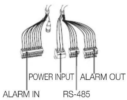
| Connectivity | RS-485/RS-422, BNC video, alarm inputs/outputs |
| Installation | Ceiling or wall, secure mounting required |
| Maintenance and Cleaning | Clean with a dry cloth; do not spray water directly |
| Safety | Use only the specified adapter; do not expose to rain or moisture |
| Included Accessories | Mounting frame, cover, connectors, user manual |
Frequently Asked Questions - SCCC6455 SAMSUNG
User questions about SCCC6455 SAMSUNG
0 question about this device. Answer the ones you know or ask your own.
Ask a new question about this device
Download the instructions for your Surveillance Camera in PDF format for free! Find your manual SCCC6455 - SAMSUNG and take your electronic device back in hand. On this page are published all the documents necessary for the use of your device. SCCC6455 by SAMSUNG.
USER MANUAL SCCC6455 SAMSUNG
Smart Dome Camera User Manual
imagine the possibilities
Thanks you for purchasing this Samsung product.
To receive a more complete service, please visit our website
www.samsungsecurity.com
CAUTION
RISK OF ELECTRIC SHOCK. DO NOT OPEN

CAUTION: TO REDUCE THE RISK OF ELECTRIC SHOCK, DO NOT REMOVE COVER (OR BACK) NO USER SERVICEABLE PARTS INSIDE. REFER SERVICING TO QUALIFIED SERVICE PERSONNEL.
This symbol indicates that dangerous voltage consisting a risk of electric shock is present within this unit.

This symbol indicates that there are important operating and maintenance instructions in the literature accompanying this unit.
WARNING
- To reduce the risk of fire or electric shock, do not expose this appliance to rain or moisture.
- To prevent injury, this apparatus must be securely attached to the floor/wall in accordance with the installation instructions.
WARNING
- Be sure to use only the standard adapter that is specified in the specification sheet. Using any other adapter could cause fire, electrical shock, or damage to the product.
- Incorrectly connecting the power supply or replacing battery may cause explosion, fire, electric shock, or damage to the product.
- Do not connect multiple cameras to a single adapter. Exceeding the capacity may cause abnormal heat generation or fire.
- Securely plug the power cord into the power receptacle. Insecure connection may cause fire.
- When installing the camera, fasten it securely and firmly. The fall of camera may cause personal injury.
- Do not place conductive objects (e.g. screwdrivers, coins, metal parts, etc.) or containers filled with water on top of the camera. Doing so may cause personal injury due to fire, electric shock, or falling objects.
- Do not install the unit in humid, dusty, or sooty locations. Doing so may cause fire or electric shock.
2\_ overview
- If any unusual smells or smoke come from the unit, stop using the product. In such case, immediately disconnect the power source and contact the service center. Continued use in such a condition may cause fire or electric shock.
- If this product fails to operate normally, contact the nearest service center. Never disassemble or modify this product in any way. (SAMSUNG is not liable for problems caused by unauthorized modifications or attempted repair.)
- When cleaning, do not spray water directly onto parts of the product. Doing so may cause fire or electric shock
- Do not expose the product to the direct airflow from an air conditioner. Otherwise, it may cause moisture condensation inside the Clear Dome due to temperature difference between internal and external of the dome camera.
- If you install this product in a low-temp area such as inside a cold store, you must seal up the wiring pipe with silicon, so that the external air can not flow inside the housing. Otherwise, external high, humid air may flow inside the housing, pooling moisture or vapor inside the product due to a difference between internal and external temperature.
CAUTION
- Do not drop objects on the product or apply strong blows to it. Keep away from a location subject to excessive vibration or magnetic interference.
- Do not install in a location subject to high temperature (over 50^ C), low temperature (below -10^ C), or high humidity. Doing so may cause fire or electric shock.
- If you want to relocate the already installed product, be sure to turn off the power and then move or reinstall it.
- Remove the power plug from the outlet when there is a lighting storm. Neglecting to do so may cause fire or damage to the product.
- Keep out of direct sunlight and heat radiation sources. It may cause fire.
- Install it in a place with good ventilation.
- Avoid aiming the camera directly towards extremely bright objects such as sun, as this may damage the CCD image sensor.
- Apparatus shall not be exposed to dripping or splashing and no objects filled with liquids, such as vases, shall be placed on the apparatus.
- The Mains plug is used as a disconnect device and shall stay readily operable at any time.
- When using the camera outdoors, moisture may occur inside the camera due to temperature difference between indoors and outdoors. For this reason, it is recommended to install the camera indoors. For outdoor use, use the camera with built-in fan and heater.
IMPORTANT SAFETY INSTRUCTIONS
- Read these instructions.
- Keep these instructions.
- Heed all warnings.
-
Follow all instructions.
-
Do not use this apparatus near water.
-
Clean only with dry cloth.
-
Do not block any ventilation openings. Install in accordance with the manufacturer's instructions.
-
Do not install near any heat sources such as radiators, heat registers, or other apparatus (including amplifiers) that produce heat.
-
Do not defeat the safety purpose of the polarized or grounding-type plug. A polarized plug has two blades with one wider than the other. A grounding type plug has two blades and a third grounding prong. The wide blade or the third prong is provided for your safety. If the provided plug does not fit into your outlet, consult an electrician for replacement of the obsolete outlet.
-
Protect the power cord from being walked on or pinched particularly at plugs, convenience receptacles, and the point where they exit from the apparatus.
-
Only use attachments/accessories specified by the manufacturer.
-
Use only with the cart, stand, tripod, bracket, or table specified by the manufacturer, or sold with the apparatus. When a cart is used, use caution when moving the cart/apparatus combination to avoid injury from tip-over.
-
Unplug this apparatus during lightning storms or when unused for long periods of time.

natural_image
Symbolic icon of a person climbing a ladder inside a circle with no text or symbols- Refer all servicing to qualified service personnel. Servicing is required when the apparatus has been damaged in any way, such as powersupply cord or plug is damaged, liquid has been spilled or objects have fallen into the apparatus, the apparatus has been exposed to rain or moisture, does not operate normally, or has been dropped.

Apparatus shall not be exposed to dripping or splashing and no objects filled with liquids, such as vases, shall be placed on the apparatus
4\_ overview
OVERVIEW
2
4 Important Safety Instructions
5 Contents
6 Features
6 What's Included
7 At a Glance
INSTALLATION & CONNECTION
8
8 Preparing Installation
8 Installation
12 Initial Setup
15 Connecting With Other Device
SETUP
18
18 How to use the Keyboard Controller
19 Main Menu
20 Profi le
22 Camera Set
31 Intelligent Video
32 Privacy Zone
33 Preset
35 Auto Set
39 Zone Set
40 Alarm Set
42 Clock Set
42 Other Set
44 Communication
44 System Info
45 Language
APPENDIX
46
46 Shortcut Keys
47 Specifications
49 Product Appearance
FEATURES
- With the state-of-the-art digital signal processing technology, full digital image processing and special algorithm of 600-line high resolution implemented
- High performance surveillance camera, equipped with x43 zoom lens and digital zoom IC, enabling monitoring up to 688 times
- WDR to cover the full screen regardless of its brightness
- DAY/NIGHT to improve the sensitivity by automatic conversion into the black and white mode at night or in the environment with low illumination
- White Balance to control the brightness to the illumination
- Backlight Compensation under spotlight or utmost bright illumination
• Auto Focus to automatically adjust the focus to the subject movement - Privacy zone to hide a specific area for personal privacy
• PAN/TILT for precise control at high speed
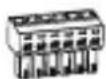
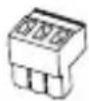
WHAT'S INCLUDED
Please check if your camera and accessories are all included in the product package.
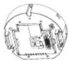
natural_image
Technical line drawing of a mechanical component with no visible text or symbolsCamera Frame Set Cover
natural_image
Technical line drawing of a mechanical assembly or housing (no visible text or symbols)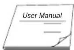
User Manual Template Connectors
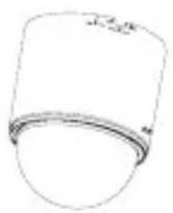
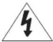
natural_image
Simple line drawing of a cylindrical object with a curved base and top edge (no text or symbols)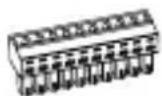

CAMERA
FRAME SET

- Wipe out a dirty surface of the lens softly with a lens tissue or cloth to which you have applied ethanol.
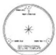
PREPARING INSTALLATION
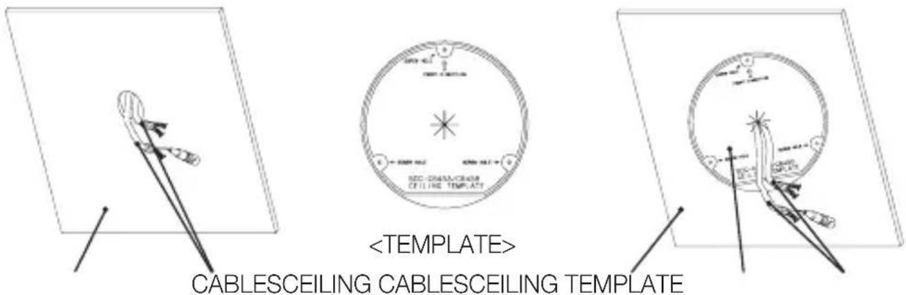
- Use the ceiling installation template when you install the camera on the ceiling on your own.
- Run the cables through the “*” shaped hole on the center of the template, and remove films on the adhesives, and then attach the template on the desired location on the ceiling.
- When installing the frames set, align all template's screw holes and those of the frames set.
- This template prevents dust entering from the ceiling into the camera assembly.
INSTALLATION
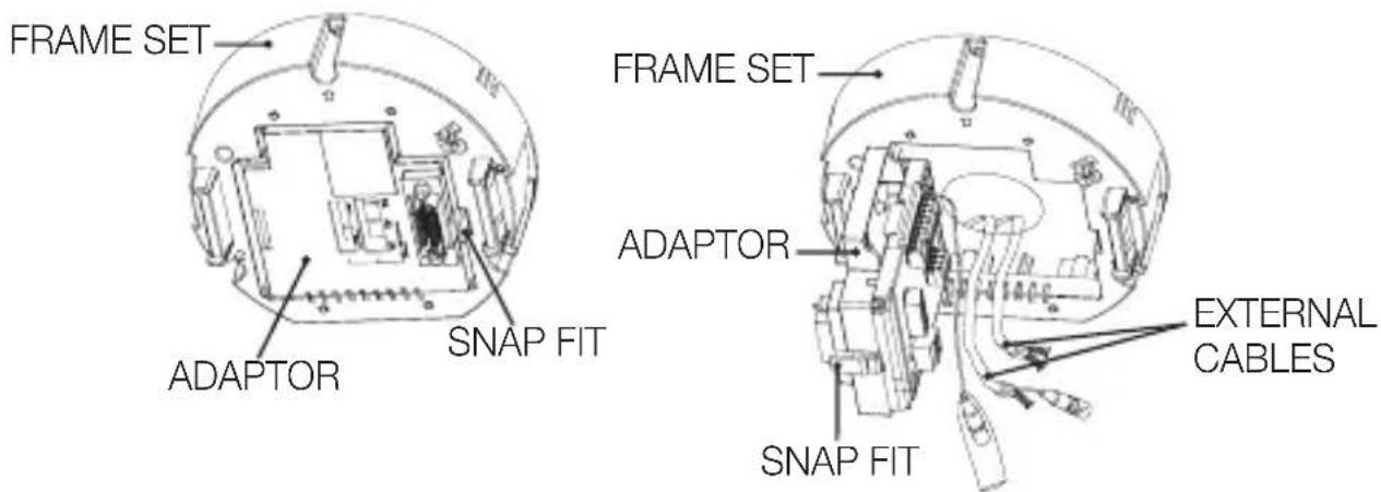
- Press the "SNAP FIT" on the "ADAPTOR" to open the "ADAPTOR", and arrange cables so they pass out of the "FRAME SET".
8_ installation & connection
- Use the three "SCREWS" to fix the "FRAME SET" on a "CAMERA" installation position.
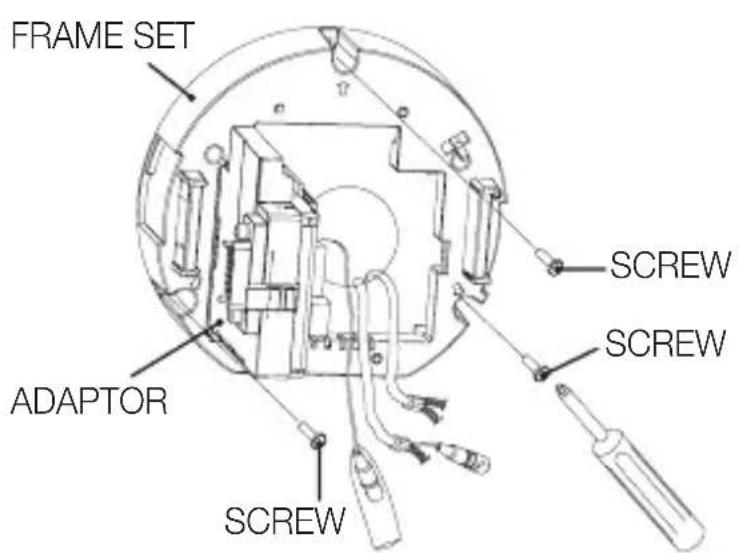
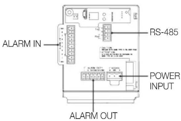
- Connect external cables to the "CONNECTORS(ALARM IN, POWER, RS-485, ALARM OUT)" and connect the "CONNECTOR" to the "ADAPTOR". Insert the cable into the "FRAME SET", and close the "ADAPTOR".
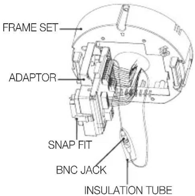


- Then, wrap the “BNC JACK” with the “INSULATION TUBE”, and use an insulation tape to seal up the end of the “INSULATION TUBE” so that the “BNC JACK” does not protrude outside of the “INSULATION TUBE” coating.
For more information about cable connection, refer to "Connecting the adaptor cable". (page 17)
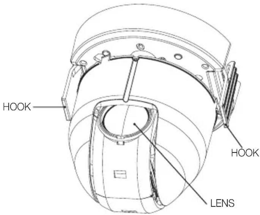
- Connect the "SAFETY WIRE" of the "CAMERA" to the "BRACKET WIRE" on the "FRAME SET". Arrange the "22P CONNECTOR" of the "CAMERA" in line with that of the "ADAPTOR", push the "HOOK" on either end of the "CAMERA" in the "RACK" direction of the "FRAME SET" to secure the two.
Then, ensure that all of the two "HOOKS" "clicks" to fix to the "RACK" properly.
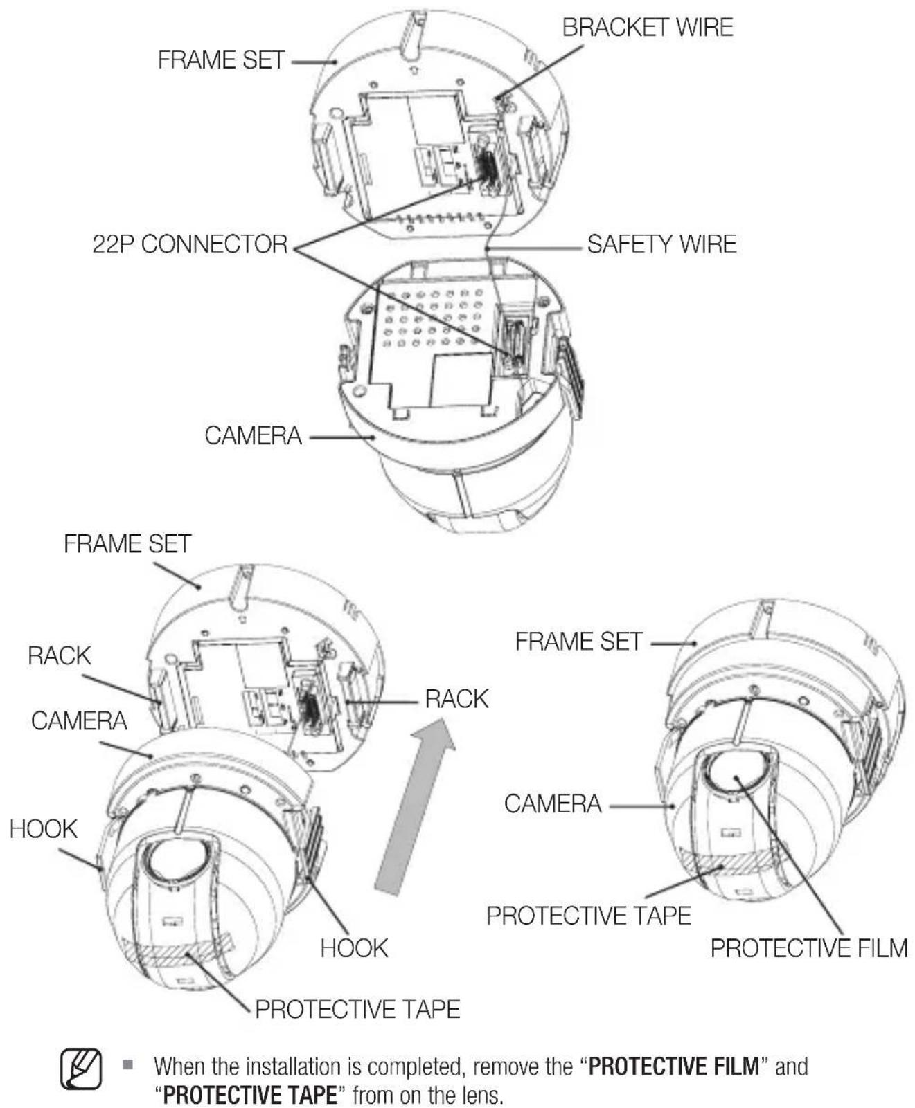
- When the installation is completed, remove the “PROTECTIVE FILM” and “PROTECTIVE TAPE” from on the lens.
10\_ installation & connection
- Arrange the "COVER" arrow in line with the "FRAME SET" arrow, and push in the "COVER". Insert the "COVER" to the end, and turn the "COVER" clockwise.
As shown in the figure below, turn it until you see the "BUTTON" hole and hear a click.
- Ensure that the “COVER” should not move any further if you turn the “COVER” counter clockwise.
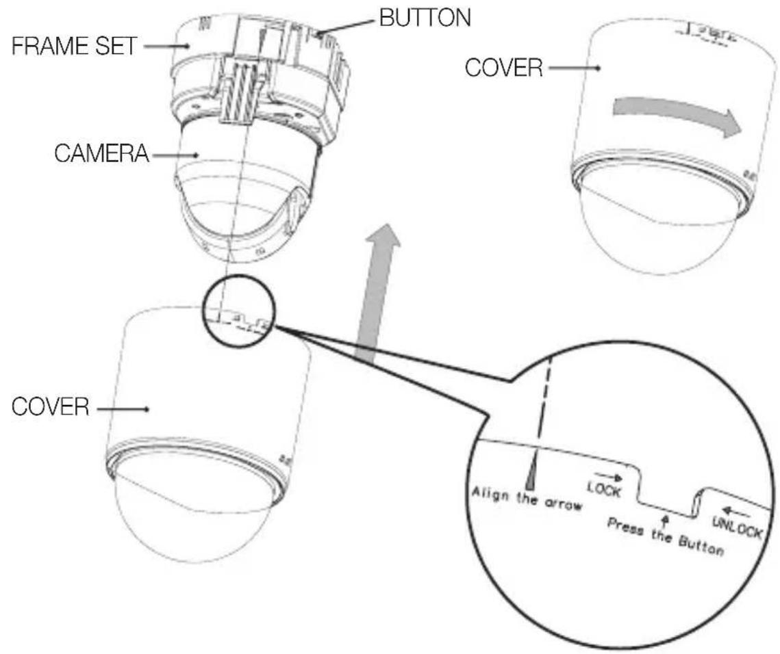
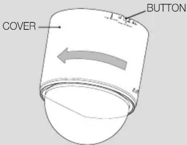
If you want to remove the "COVER", hold down the "BUTTON" and turn the "COVER" counter clockwise to remove the "COVER".
INITIAL SETUP
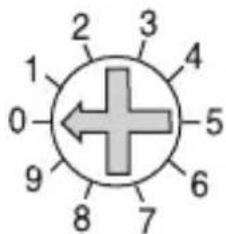
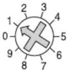
Camera Address Setup
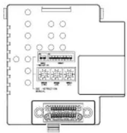
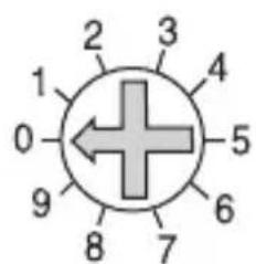
Use SW606, SW605, and SW604 to specify the camera address.
You can specify between 0 and 255 for the address, where the hundreds digit is with SW606, the tens digit with SW605, and the ones digit with SW604.
ex) Camera address: If the address is 1, follow the steps in the figure below.
SW606
(x100)
SW605
(x10)
SW604
(x1)
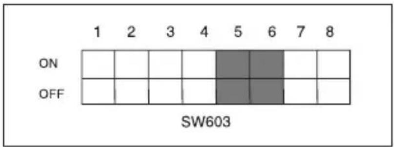
Communication Protocol Setup
Use pins #1\~#4 of SW603 to specify the communication protocol.
| PIN Comp | PIN1 | PIN2 | PIN3 | PIN4 | |
| A OFF | OFF | OFF | OFF | ||
| B ON | OFF | OFF | OFF | ||
| C OFF | ON | OFF | OFF | ||
| D ON | ON | OFF | OFF | ||
| E OFF | OFF | ON | OFF | ||
| F ON | OFF | ON | OFF | ||
| G OFF | ON | ON | OFF | ||
| H ON | ON | ON | OFF | ||
| I OFF | OFF | OFF | ON | ||
| J ON | OFF | OFF | ON | ||
| K OFF | ON | OFF | ON | ||
| L ON | ON | OFF | ON | ||
| M OFF | OFF | ON | ON | ||
| N ON | OFF | ON | ON | ||
| O OFF | ON | ON | ON | ||
| P | O | N | O | N |
12\_ installation & connection
Baud Rate Setup
Use pins #5, #6 of SW603 to set the baud rate.
| BAUD RATE PIN 5 PIN 6 | ||
| 4800 BPS ON ON | ||
| 9600 BPS OFF ON | ||
| 19200 BPS ON OFF | ||
| 38400 BPS OFF OFF |
The factory default is 9600 BPS.
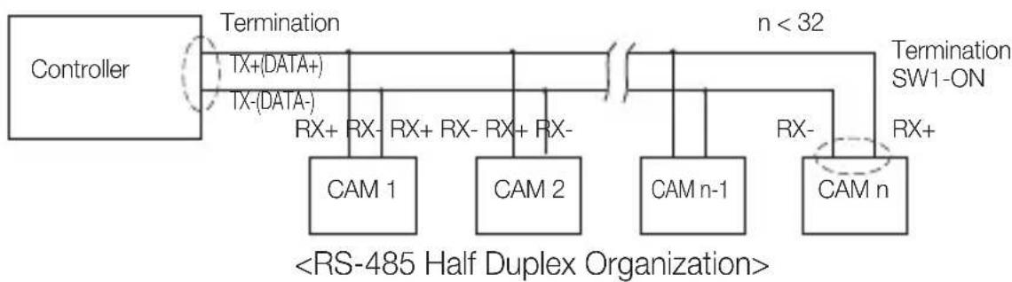
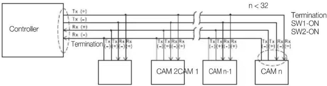
Setting RS-422A/RS-485 Termination
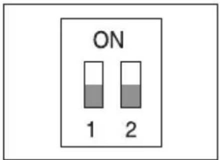
As it is shown in the structure map, when Controller and RS-422A/RS-485 is connected, it should be terminated according to the Cable feature of impedance on the each end of the transmitting line to transfer the signals in long distance by controlling the reflection of the signals to the lowest.
flowchart
graph LR
    A["Controller"] -->|Termination TX+(DATA+) TX-(DATA-)| B["CAM 1"]
    A -->|Termination TX-(DATA-) RX+ RX- RX+ RX- RX+ RX-| C["CAM 2"]
    A -->|Termination SW1-ON n < 32| D["CAM n-1"]
    A -->|Termination SW1-ON RX+| E["CAM n"]
    B --> F["<RS-485 Half Duplex Organization>"]
    C --> F
    D --> F
    E --> F
Termination : Using numbers 1 and 2 PIN, turn to
flowchart
graph TD
    A["Controller"] -->|Tx {+}| B["CAM 2CAM 1"]
    A -->|Tx {-}| B
    A -->|Rx {+}| C["CAM n-1"]
    A -->|Rx {-}| C
    B --> D["Tx {-} (−) Tx (+) (-) Rx (+) +"]
    C --> E["Tx {-} (−) Tx (+) (-) Rx (+) +"]
    F["Termination"] --> B
    G["n < 32"] --> H["CAM n"]
    I["Termination SW1-ON"] --> H
    J["Termination SW2-ON"] --> H
    K["Termination SW1-ON"] --> H
    L["Termination SW2-ON"] --> H

A communication error may occur if you connect multiple cameras that are assigned the same address in the network.
flowchart
graph TD
    A["MONITOR"] --> B["ALARM IN"]
    B --> C["ALARM OUT"]
    C --> D["POWER SOURCE"]
    D --> E["CONTROLLER/DVR"]
    E --> F["Computer"]
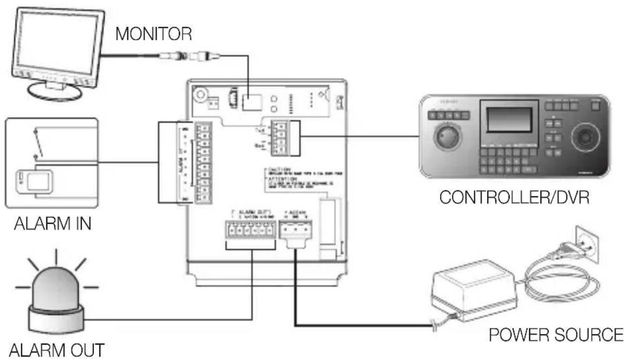
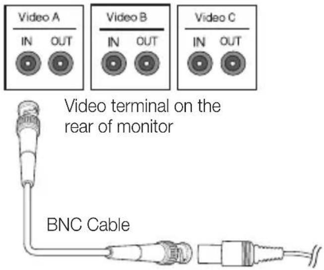
Connecting to a monitor
- Connect one end of the BNC video cable connector to the Video Output Terminal (VIDEO OUT).
- Connect the other end of the connector to the Video Input Terminal of the monitor.
To connect ALARM IN
- Connect one end of the external device's signal line to a corresponding ALARM IN port of the monitor.
- Connect the other end of the signal line to the earth-grounding [GND] port.
To connect ALARM OUT
- Connect one end of the external device's signal line to a corresponding ALARM OUT port of the monitor.
- Connect the other end of the signal line to the common [COM] port.
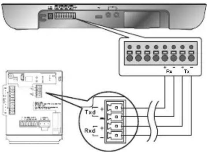
To connect the controller
Connect an external controller or DVR to the camera, with which you can adjust the camera.
- Connect the Rx+ pin of the camera to the Tx+ pin of the controller.
- Connect the Rx-pin of the camera to the Tx-pin of the controller.
- Connect the Tx+ pin of the camera to the Rx+ pin of the controller.
- Connect the Tx- pin of the camera to the Rx- pin of the controller.
Connecting the adaptor cable
Adaptor Board
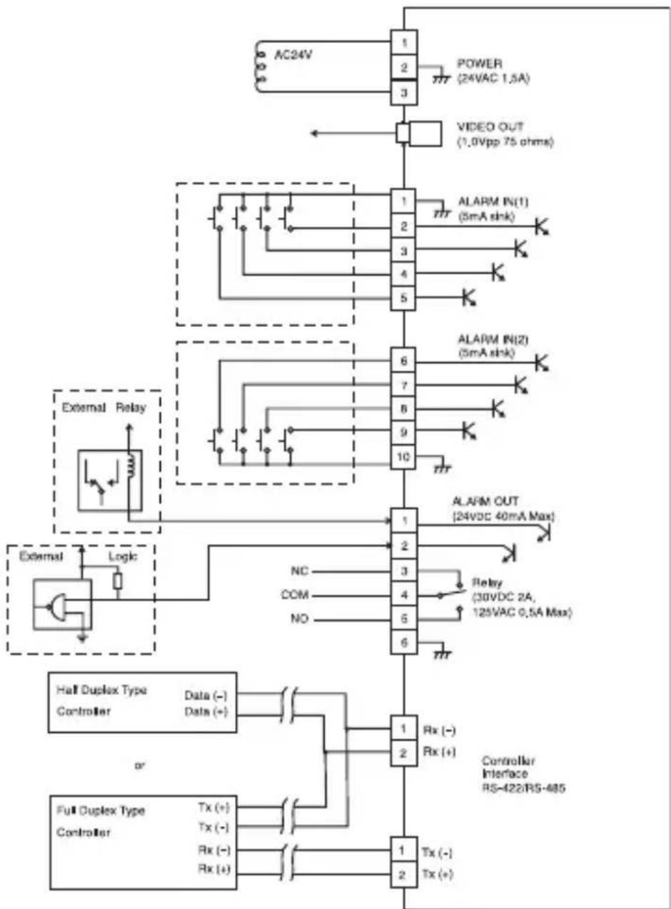
flowchart
graph TD
    A["AC24V"] --> B["1"]
    B --> C["POWER (24VAC 1.5A)"]
    B --> D["3"]
    D --> E["VIDEO OUT (1.0Vpp 75 ohms)"]
    E --> F["External Relay"]
    F --> G["External Relay"]
    G --> H["Logic"]
    H --> I["External Relay"]
    I --> J["Half Duplex Type Controller"]
    J --> K["Data (-) Data (+)"]
    K --> L["Controller Interface RS-422/RS-485"]
    M["Full Duplex Type Controller"] --> N["Tx (+) Tx (-)"]
    N --> O["Rx (-) Rx (+)"]
    O --> P["Tx (-) Tx (+)"]
    Q["ALARM IN(1) (5mA shk)"] --> R["1"]
    R --> S["ALARM IN(2) (5mA shk)"]
    T["ALARM OUT (24VDC 40mA Max)"] --> U["1"]
    U --> V["ALARM OUT (24VDC 40mA Max)"]
    W["NC"] --> X["COM"]
    X --> Y["NO"]
    Z["Relay (30VDC 2A, 125VAC 0.5A Max)"] --> AA["6"]
    AA --> AB["6"]
    AC["External Relay"] --> AD["External Relay"]
Power Supply
Connect the cables as necessary, and turn on the camera to check if it works properly.
- Connect the adaptor to the power terminal of the camera.
- Plug the power cord of the adaptor into the wall outlet.
Connect the camera to the keyboard controller or DVR, with which you can manipulate and change the settings of the camera.
HOW TO USE THE KEYBOARD CONTROLLER
Follow the steps below to set the camera menu using the controller.
- Open the Camera Setup screen.
- Use the joystick to navigate through the menus.
- Press [ENTER] to select a menu item.
- Use the joystick to change the value of the selected item.
- Press [ENTER] to apply your changes.
Using OSD icons
- ◀▶: If these icons appear in the left and right corner of a menu item, you can use the joystick to move to the previous or next menu.
- (EXIT): Exits the menu setup screen.
Before exiting the setup screen, select
to save your settings to the whole menus, or to cancel them. - (RET): Saves your settings and returns to the previous screen.
• (HOME): Returns to the main menu. - (SAVE): Use this icon if you want to save your settings after you specified the mask area and privacy area, etc.
Once you saved your settings, the changes remain intact even if you select
- (DEL): Use this icon if you want to delete a mask, or privacy area, etc. Once you deleted your settings, the deletions remain valid even if you select
• 📁: This icon appears in the right of a menu containing sub menu items.

While any operation of PRESET, AUTO PAN, SCAN, and PATTERN is running, and if the camera is turned off and back on without any particular manipulation, the camera will resume the last run operation.
- You can set the menu item only if the tilt angle is within 90°.
If you enter the menu setup screen with the camera positioned out of a tilt of 90°, the camera will rotate by 180° to fall into the opposite position within a tilt of 90°.
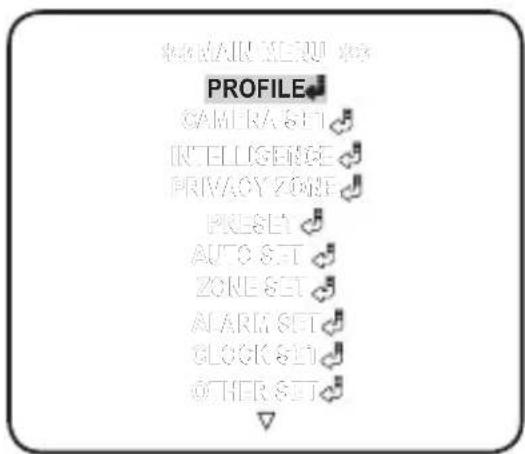
This is the first screen you ever see when you turn on the camera where you can set the camera environment to your needs.
For selecting and saving each menu item, refer to "How to use the keyboard controller". (page 18)
- PROFILE
Select a mode appropriate to the camera installation environment.
- CAMERA SET
You can configure the camera settings.
• INTELLIGENCE
Offers motion detection and tracking functions.
- PRIVACY ZONE
You can configure the privacy settings.
- PRESET
You can set the PRESET POSITION and DURATION.
- AUTO SET
Contains sub menu items of AUTO PAN, PATTERN, and SCAN.
- ZONE SET
You can set the standard azimuth and zone area for the camera.
- ALARM SET
You can set the alarm priority and I/O sequence.
- CLOCK SET
You can set the display time and format.
- OTHER SET
You can reset the camera, or adjust the OSD color to your preference.
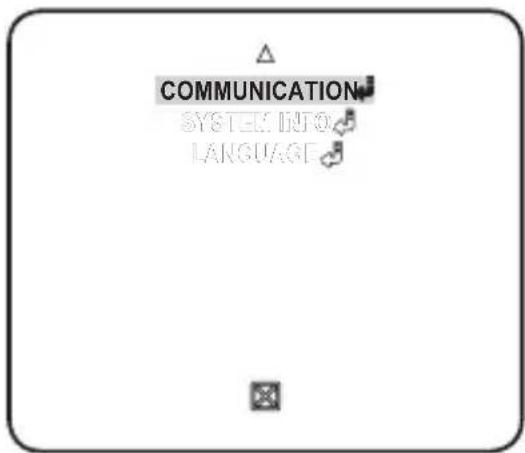
• COMMUNICATION
Configures the settings pertaining to RS-485 communication.
- SYSTEM INFO
Shows the system information such as the camera version or communication settings.
- LANGUAGE
Select a preferred one from the supported languages.
PROFILE
You can select one from the pre-determined configurations as appropriate to your specific camera installation environment.
Your selection on each item in PROFILE will affect all other settings of the camera.
- STANDARD
Automatically optimizes the camera settings to the normal environment.
• ITS
This setting enables you to analyze the traffic situation and take the traffic information at a glance.
- BACKLIGHT
This setting enables you to view a sharp background and object even in a severe backlight scene.
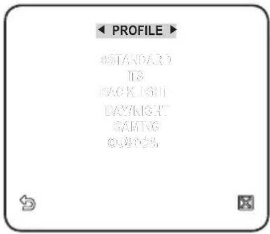
- DAY/NIGHT
Automatically optimizes the camera settings to the day and night scene.
• GAMING
This automatically configures the settings so that you can work in a stable illumination condition as indoors.
- CUSTOM
Your change to any of the PROFILE settings will switch the display to CUSTOM.
| CAMERA SETUP MENU | STANDARD ITS BACKLIGHT DAY/NIGHT GAMING | |||||
| Parent Menu | Sub-menus | |||||
| VPS OFF | ON OFF OFF OFF | |||||
| IRIS | ALC ALC ALC ALC ALC | |||||
| ALC - | - | - | - | - | ||
| LEVEL 0 | 0 | 0 | 0 | 0 | ||
| BACKLIGHT OFF OFF WDR OFF OFF | ||||||
| WDR - | - | - | - | - | ||
| WEIGHT | Custom Setting | Custom Setting | MEDIUM | Custom Setting | Custom Setting | |
| WDR LEVEL | Custom Setting | Custom Setting | 0 | Custom Setting | Custom Setting | |
| WHITE BAL | Custom Setting | Custom Setting | Custom Setting | Custom Setting | Custom Setting | |
| CAMERA SETUP MENU | STANDARD ITS BACKLIGHT DAY/NIGHT GAMING | |||||
| Parent Menu Sub-menus | ||||||
| MOTION | (F.FAST)--- | (F.FAST)--- | NORM | (F.FAST)--- | SLOW | |
| DNR MEDIUM MEDIUM MEDIUM MEDIUM MEDIUM MEDIUM | ||||||
| SHUTTER OFF OFF OFF OFF | ||||||
| SENSE UP AUTO X4 AUTO X2 AUTO X4 AUTO X4 AUTO X4 | ||||||
| XDR MEDIUM MEDIUM MEDIUM MEDIUM MEDIUM MEDIUM | ||||||
| DAY/NIGHT | AUTO AUTO DAY AUTO DAY | |||||
| NIGHT - | - | - | - | - | ||
| BURST OFF ON OFF OFF OFF | ||||||
| EXT | - | - | - | - | - | |
| BURST OFF ON OFF OFF OFF | ||||||
| WHITE BAL | DAY | DAY/NIGHT | DAY | DAY/NIGHT | DAY | |
| DAY | - | - | - | - | - | |
| MODE | ATW2 | ATW1 | ATW1 | ATW1 | ATW1 | |
| RED | 0 | 0 | 0 | 0 | 0 | |
| BLUE | 0 | 0 | 0 | 0 | 0 | |
| NIGHT - | - | - | - | - | ||
| BRIGHTNESS | Custom Setting | MEDIUM | Custom Setting | MEDIUM | Custom Setting | |
| MODE OFF ATW2 | OFF ATW2 | OFF | ||||
| RED | Custom Setting | 0 | Custom Setting | 0 | Custom Setting | |
| BLUE | Custom Setting | 0 | Custom Setting | 0 | Custom Setting | |
| DETAIL | 2 | 2 | 2 | 2 | 2 | |
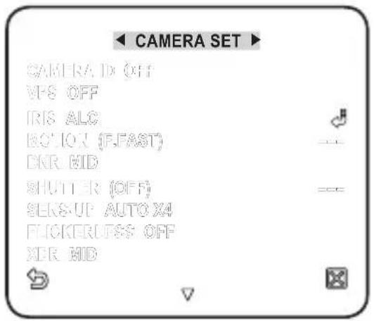
CAMERA SET
You can configure the general settings of the camera module.
For selecting and saving each menu item, refer to "How to use the keyboard controller". (page 18)
-
Select
- . The Camera Setup menu appears. -
Change the settings as necessary, or select an item to check.
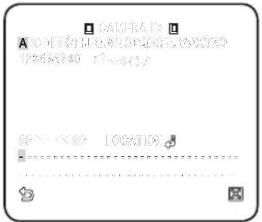
CAMERA ID
Provide the ID and location for a camera that displays on the screen.
For selecting and saving each menu item, refer to "How to use the keyboard controller". (page 18)
- Select
- . - Use the joystick to select a desired character, then press [ENTER].
In the lower input box of the screen, the selected character will be entered.
■ You can enter up to 54 characters including alphabets, numbers and special characters.
- LOCATION : Specify the display position of the camera ID.
- When done, press [ENTER].
The camera ID will be displayed in the specified position.
VPS
If you set it to
IRIS
The IRIS menu is useful if you set to adjust the intensity of radiation incoming to the camera.
• ALC : Adjust the open and close of the iris.
- LEVEL : Select an overall brightness level.
- BLC : With
With AREA set to
![ALO LEVEL [ 00] ----1---- BACKLIGHT BLC AREA USER](/content/2026/03/529023/images/7409b2b1be81d189b9f36f199f03d463412a049eea08cf85233f7bfae53f8e0f.jpg)
- WDR : If you set
Specify the shutter speed in WDR LEVEL, and, the composition level in
The WDR feature provides an extension of the gain range, which is useful, especially if you work on pictures both indoors and outdoors from inside of a building.
![ALG LEVEL [ 00] ...... BACKLIGHT WDR WEIGHT MID WOR LEVEL [ 0] ...... WHITE BAL NDOOR](/content/2026/03/529023/images/d5666ab7ba5392b0cf48a6211ec53400bc9a1811db27cd27bc25b048bd9c7bb5.jpg)
Namely, it improves the sharpness of the picture in outdoor scenery as well as indoor.

As long as you use the VPS function, the WDR will not be available as the CCD read method differs accordingly. If you set VPS to ON, WDR will be set to
• MANUAL : Adjust the iris level manually.

■ The overall brightness target of a camera will be set to ALC level 0, while the iris can be adjusted manually.
![MANUAL LEVEL [ 00 ----]----](/content/2026/03/529023/images/4065a3bcf9e9be463fa130b42125a8cc8810900bfce4fff0e3590bd751750360.jpg)
AGC
With this, you can adjust the AGC level of a camera.
With AGC active, if the signal strength falls below the standard level, AGC will amplify the video signal to automatically improve the sensitivity.
If
With the USER (💡) submenu selected, press [ENTER] to display the corresponding screen. In this mode, you can select from VERY LOW HIGH)
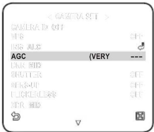
to VERY HIGH in 16 levels, enabling deeper, wider choices to your convenience.
With the FIX (💡) submenu selected, press [ENTER] to display the corresponding screen. In this mode, you can select an individualized mode in 16 levels, regardless of the brightness.

As long as the DAY/NIGHT menu is set to AUTO in Camera Setup, the AGC menu is not available.
As long as FLICKERLESS is set to ON, the AGC mode is not available.
If you set BACKLIGHT to WDR, the AGC fi x mode is not available.
MOTION
You can specify a level of AGC for controlling the camera motion.
This is available only of the SENSE UP menu is set to AUTO.
Select F.FAST if you want to monitor a very fast moving object in a low contrast scene, and S.SLOW if monitoring a very slow moving, inanimate object in the same condition.
As long as DAY/NIGHT is set to
DNR
Reduces the noise on the camera image.
The higher the level is, the greater the effect is.
Set it to
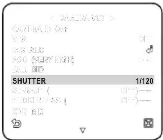
SHUTTER
You can select a fixed fast electronic shutter speed in 7 options ranging from 1/120 to 1/10k, which is mostly used to take a picture of a fast moving object.
As long as SENSE UP is set to AUTO, FIXED / FLICKERLESS to ON / BACKLIGHT to WDR, the SHUTTER menu is not available.
SENS-UP
Automatically senses the darkness level at night or in a low contrast scene, and extends the accumulation time accordingly; you can select

If the SHUTTER menu is set to fixed electronic shutter mode, the SENSE UP menu will not be available.
If FLICKERLESS is set to ON, or BACKLIGHT to WDR, the FIX mode of the SENSE UP menu is not available.
FLICKERLESS
This will prevent possible screen distortion due to a mismatch between the vertical sync frequency and the blinking frequency of the lighting; if set to
If SHUTTER is set to FIX, SENSE UP to FIX, and AGC to FIX, the
XDR
This will correct a brightness difference between different scenes for the optimal visibility by calculating the ambient luminance contrast in a certain unit of pixels. The higher the value is, the higher the correction level is.
DAY/NIGHT
You can specify a recording mode according to the scene.
For selecting and saving each menu item, refer to "How to use the keyboard controller". (page 18)
- Select
- . -
Select a screen transition mode according to the illumination, and set options as appropriate.
-
DAY : Fixed to DAY mode, regardless of the scene.
- NIGHT : Fixed to NIGHT mode, regardless of the scene.
If BURST is set to
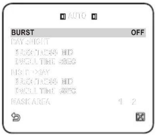
- AUTO : According to the luminance, this will switch DAY to NIGHT mode, or vice versa.
- BURST : If set to
, the burst signal will not be output in NIGHT mode. - DAY→NIGHT BRIGHTNESS : Specify the brightness level switching from COLOR to BW filter.
Adjusting from HIGH to LOW will cause to switch the filter in a darker screen.
- DAY→NIGHT DWELL TIME : Time required to determine the fi lter switch.
- NIGHT→DAY BRIGHTNESS: Specify the brightness level switching from BW to COLOR fi Iter. Adjusting from HIGH to LOW will cause to switch the fi Iter in a darker screen.
- NIGHT→DAY DWELL TIME : Time required to determine the filter switch.
- MASK AREA : If there exists a bright spot light source in a night scene, you can specify the size and position as needed.
This will prevent an error in switching fi Iter, or failure to determine the fi Iter switch in a night scene where a bright spot light source exists.
Any excessively bright area in a night scene will be MASKed.
![DAY/NIGHT AUTO WHITE DAL FOCUS MODE ONE&F ZOOM SPEED [ ] DISPLAY ZOOM OFF DISPLAY NT OFF DIGITAL ZOOM OFF DETAIL [ ] V-ASYRO INT](/content/2026/03/529023/images/a501ee6c2facc2aa2042ca0a7c138fa66bc54069150e45ab2e7e18c618e9bb91.jpg)
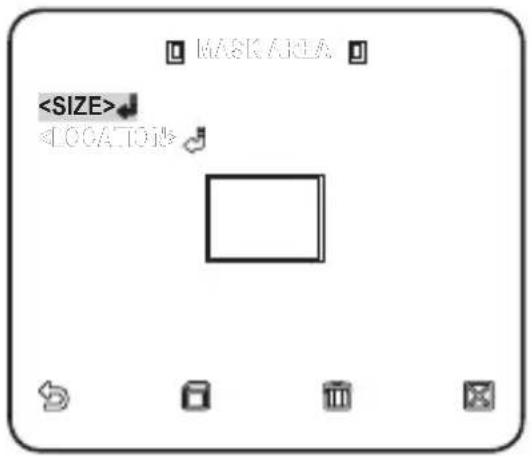
■ You can specify MASK 1 and 2 simultaneously.
If
- EXT : The interface to an external alarm enables an automatic switch between DAY and NIGHT mode.
If you set
If an alarm signal occurs, the mode will switch to NIGHT.

If
If you use an infrared light source while in AUTO mode, this may cause a failure in AUTO SWITCH or AUTO FOCUS.
WHITE BAL
If you need to adjust the color according to the ambient illumination, you can use the
For selecting and saving each menu item, refer to "How to use the keyboard controller". (page 18)
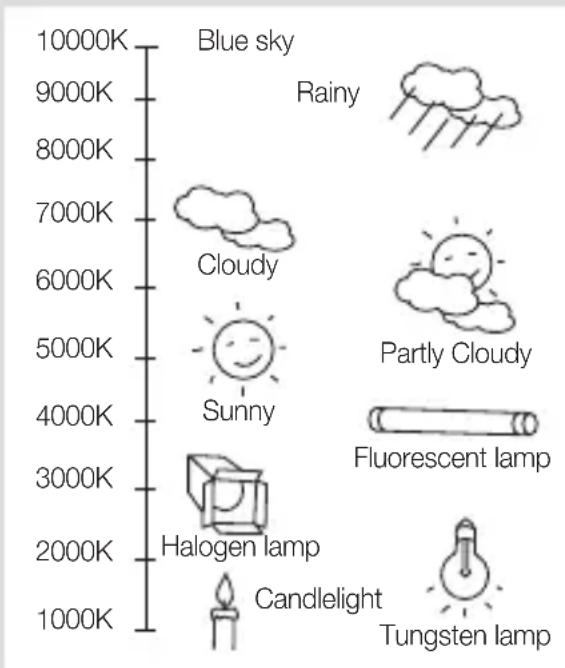
Illumination is generally referred to as color temperature, which is represented in a measurement of kelvin (K). Color temperatures for ordinary lighting are as follows:
In the
- ATW1,2 : If you set the
waterfall
| Category | Value | |---|---| | Blue sky | 10000K | | Rainy | 9000K | | Cloudy | 8000K | | Partly Cloudy | 7000K | | Sunny | 6000K | | Fluorescent lamp | 5000K | | Halogen lamp | 4000K | | Candlelight | 3000K | | Tungsten lamp | 2000K | | Candlelight (Candlelight) | 1000K |※1 : With
※2 : With
-
Select
- . -
Select a mode where you set the
.
- DAY: You can set the RED, and BLUE value in DAY mode. The screen will be displayed in colors according to your settings.
- You can set the R-GAIN, and B-GAIN value only in
If AGC is set to
![DAY/RIGHT DAY MODE AWC RED [00] ..... BLUE [00] ..... BGA1 [00/64] BGA2 [00/64]](/content/2026/03/529023/images/0a1227721cfb047bf009c3fe84f57c47a77bbbde9db6d68eec21ddcbca7c5a02.jpg)
- NIGHT : You can set the
![WETE BAL DAYLIGHT NIGHT RIGHTRESS MID MODE AWC RED [00] ..... BLUE [00] ..... ROAA [0164] BOAA [0164]](/content/2026/03/529023/images/a1ccc1679f8360ed860f741dad3dc3f8fb94edcb384551569017bbabba3dcf18.jpg)
-
According to the specified recording mode, select a
mode with necessary options. -
ATW1,2 : The camera can automatically adjust the color temperature in real time, according to the ambient conditions. (Color temperature range 1: 2500K \~ 9300K, 2 : 2000K \~ 10000K)
- AWC : Pressing [ENTER] on a desired item will perform ATW once.
■ You can set the R-GAIN/B-GAIN value.
• 3200K : Set the color temperature to 3200K. -
5600K : Set the color temperature to 5600K.
-
BRIGHTNESS : Specify a brightness level switching from DAY mode to NIGHT mode setting.
- RED : Adjust the strength of the red color.
- BLUE : Adjust the strength of the blue color.
- R-GAIN/B-GAIN : Specify the current color temperature manually.
FOCUS MODE
You can select a focus mode according to the angle that you adjusted for camera recording.
- AF : This will monitor the screen continuously to focus automatically. If you adjust the focus manually, that will operate the same as in
- ONEAF : Restores focus after the operation of pan/tile/zoom, and operates the same as in
- MF : You can adjust the focus manually.
![DAYNIGHT AUTO WHITE SAL FOCUS MODE ONEAF ZOOM SPEED [2] DISPLAY ZOOM OFF DISPLAY INT OFF DIGITAL ZOOM X10 DETAIL [2] W-SYKQ INT](/content/2026/03/529023/images/6df3688c12eda794ec3e149bc00bfb3044d9074f1155c8fdf7bb938acd676c70.jpg)

While you are working on the following objects,
- Very bright object, or dominant object in a dark scene
- Object against the rear side of a moist or dirty glass
- A scene where nearby and distant objects co-exist
- White wall or single-colored object
- Venetian blinds and other horizontally striped objects
ZOOM SPEED
You can adjust the zoom operation speed.
DISPLAY ZOOM
You can set to display the zoom status on the screen.
It will disappear in about 3 seconds if the zoom factor has no further change.
DISPLAY P/T
You can set to display the operation status of pan/tilt when it is active.
It will disappear in about 3 seconds if the pan/tilt position has no further change. However, the allowable error is ± 2^ .
DIGITAL ZOOM
You can set the maximum allowable digital zoom ratio.
Digital Zoom will start operation after it is zoomed in to the maximum optical ratio of x43. If you set DIGITAL ZOOM to x16, you can take a shot at up to x688 (43x16).
DETAIL
Used to adjust the vertical and horizontal distinction, respectively.
V-SYNC
You can set the V-SYNC mode.
- If you select
, the camera will use the internal synchronization. - If selecting
, the camera will use an external power frequency for synchronization. The LL-PHASE can be adjusted as appropriate.
AGC COLOR SUP
You can adjust the color reproduction range according to AGC.
REVERSE
You can reverse the video signal from left to right, upside down, or vice versa to your convenience.
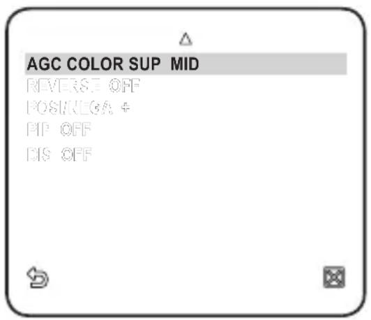
POSI/NEGA
You can set the video brightness signal to normal or reverse.
PIP
You can view a main image with a sub image on the same screen.

If more than one PRIVACY ZONE is specified, and PRIVACY SET to
As long as SENSE UP is set to FIXED, PIP menu is not available.
- According to the luminance, PIP will disappear if the SENSE UP menu is set to AUTO.
DIS (Digital Image Stabilization)
If you set it to

If you set
-
You can enable the motion detection and tracking functions.
For selecting and saving each menu item, refer to "How to use the keyboard controller". (page 18)
- Select
- . - Select each item and set appropriately.
MOTION
You can enable the motion detection and tracking functions.

If you set it to
![INTELLIGENCE MOTION OFF ADVANCED OFF MASKAREA 1 2 3 4 DISPLAY ON SENSITIVITY [4] RESOLUTION [3] ALARMOUT](/content/2026/03/529023/images/17f1fc0092a1ee3675dcdc7eb18126b712ef3cec62d4ab2a1b82daa081b08fe5.jpg)
In following situations, motion detection and tracking function may not work properly.
- When there is sudden changes of brightness
- When the device moves
- When a certain object's movement fills most of the framing area
- When there is difficulties in distinguishing the moving object and background
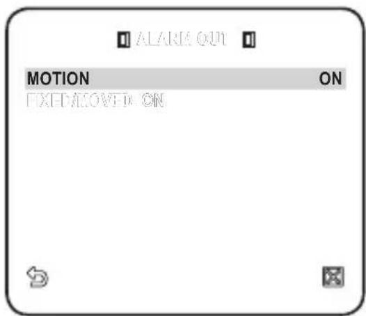
ADVANCED
You can detect motions and mark the video that contains such motion, and enables tracking of the movement. (The auto PTZ function is not supported for tracking an object.) Selecting the

In following situations, FIXED/MOVED detection may not work properly.
- When multiple motions continue arbitrarily.
- When the object that is fixed continues to move in the same position.
- When a newly appearing object conceals another object that is moving.
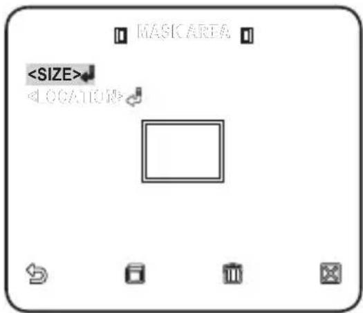
MASK AREA
- Select the number of the area to be masked that will be excluded from motion detection.
- Select the mask number and set the mask size and its coverage.
DISPLAY
When selected
SENSITIVITY
Sets the sensitivity of motion sensor.
RESOLUTION
The bigger the resolution setting, the smaller the object that can be detected.
ALARM OUT
When selected
PRIVACY ZONE
You can set up to 12 privacy zones that will be hided for privacy of the subject when recording.
Zone Setup
For selecting and saving each menu item, refer to "How to use the keyboard controller". (page 18)
- Select
- . -
Select the number of the zone and press [ENTER].
The Zone setup screen appears. -
Select the
and press [ENTER].
Using the joystick, adjust the camera's pan, tilt and zoom.
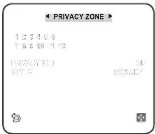
- Select the
. Select the pixel level for the SIZE and LOCATION settings. - Select the
and press [ENTER]. Using the joystick, set the size of the privacy zone. - Select the
and press [ENTER]. Using the joystick, set the position of the privacy zone. - Save the changes and move to the previous screen and select the

- Smart Dome Camera User Manual
- imagine the possibilities
- CAUTION
- WARNING
- 2\_ overview
- IMPORTANT SAFETY INSTRUCTIONS
- 4\_ overview
- OVERVIEW
- INSTALLATION & CONNECTION
- SETUP
- APPENDIX
- FEATURES
- WHAT'S INCLUDED
- PREPARING INSTALLATION
- INSTALLATION
- 10\_ installation & connection
- INITIAL SETUP
- Camera Address Setup
- Communication Protocol Setup
- 12\_ installation & connection
- Baud Rate Setup
- Setting RS-422A/RS-485 Termination
- Connecting to a monitor
- To connect ALARM IN
- To connect ALARM OUT
- To connect the controller
- Connecting the adaptor cable
- Power Supply
- HOW TO USE THE KEYBOARD CONTROLLER
- Using OSD icons
- - PROFILE
- - CAMERA SET
- • INTELLIGENCE
- - PRIVACY ZONE
- - PRESET
- - AUTO SET
- - ZONE SET
- - ALARM SET
- - CLOCK SET
- - OTHER SET
- • COMMUNICATION
- - SYSTEM INFO
- - LANGUAGE
- PROFILE
- - STANDARD
- • ITS
- - BACKLIGHT
- - DAY/NIGHT
- • GAMING
- - CUSTOM
- CAMERA SET
- CAMERA ID
- VPS
- IRIS
- AGC
- MOTION
- DNR
- SHUTTER
- SENS-UP
- FLICKERLESS
- XDR
- DAY/NIGHT
- WHITE BAL
- FOCUS MODE
- ZOOM SPEED
- DISPLAY ZOOM
- DISPLAY P/T
- DIGITAL ZOOM
- DETAIL
- V-SYNC
- AGC COLOR SUP
- REVERSE
- POSI/NEGA
- PIP
- DIS (Digital Image Stabilization)
- ADVANCED
- MASK AREA
- DISPLAY
- SENSITIVITY
- RESOLUTION
- ALARM OUT
- PRIVACY ZONE
- Zone Setup
- PRESET
- AUTO SET
- Auto Pan Setup
- Pattern Setup
- Scan Setup
- Auto Play Setup
- ALARM SET
- CLOCK SET
- OTHER SET
- FACTORY DEFAULTS
- OSD COLOR
- PROPORTIONAL P/T
- P/T SPEED
- AUTO CAL. (AUTO CALIBRATION)
- D-FLIP (DIGITAL FLIP)
- PASSWORD
- COMMUNICATION
- SYSTEM INFO
- Correct Disposal of This Product (Waste Electrical & Electronic Equipment)
- Caméra Smart Dome Manuel d'utilisation
- Imaginez les possibilités
- ATTENTION
- MISE EN GARDE
- 4\_ présentation
- PRÉSENTATION
- INSTALLATION ET CONNEXION
- CONFIGURATION
- ANNEXE
- CARACTÉRISTIQUES
- CONTENU
- 6\_ présentation
- PRÉPARATION DE L'INSTALLATION
- 10\_ installation et connexion
- CONFIGURATION INITIALE
- Configuration de l'adresse caméra
- Configuration du protocole de communication
- Configuration du débit de bauds
- Parametrage RS-422A/Connexion de Sortie RS-485
- Connexion de l'appareil à un écran
- Pour connecter ALARM IN
- Pour connecter ALARM OUT
- Pour connecter le contrôleur
- Connexion du câble-adaptateur
- Alimentation
- MODALITÉ D'UTILISATION DU CONTRÔLEUR DE CLAVIER
- Utilisation d'icônes d'affichage à l'écran
- • PROFIL
- - REG CAMERA
- - ZONE PRIVEE
- - PREDEFINI
- - REGL AUTO
- - REGL ZONE
- - REGL ALARME
- - REG HORLOGE
- - AUTRE REG
- - INFO SYSTEME
- • LANGUE
- PROFIL
- • RÉTROÉCL
- • JOUR/NUIT
- • JEU
- - PERSONNALISE
- REG CAMERA
- ID DE CAMERA
- > < # P O T I O N
- MOUVEMENT
- OBTURATEUR
- AUGMENTER SENS.
- ANTI-BATTEMENT
- JOUR/NUIT
- BAL BLANCS
- MODE FOCUS
- VITESSE ZOOM
- AFFICHAGE ZOOM
- AFFICHAGE P/T
- ZOOM NUM
- AGC SUP COULEUR
- INVERSE
- SIN (Stabilisation d'image numérique)
- MOUVE
- AVANCE
- ZONE MASQUAGE
- AFFICHAGE
- SENSIBILITE
- SORT ALARME
- ZONE PRIVEE
- Configuration de zone
- 32\_ configuration
- PREDEFINI
- REGL AUTO
- Configuration du panoramique auto
- Configuration de la ronde
- Configuration du balayage
- Configuration de la lecture automatique
- REGL ALARME
- REG HORLOGE
- AUTRE REG
- REINIT REGLAGE USINE
- COULR OSD
- P/T PROPORT.
- P/T VITESSE
- CALIBR. AUTO (CALIBRAGE AUTO)
- ROT NUM (ROTATION NUMERIQUE)
- MDP
- INFO SYSTEME
- Les bons gestes de mise au rebut de ce produit (Déchets d'équipements électriques et électroniques)
- SmartDome-Kamera Benutzerhandbuch
- erleben sie die möglichkeiten
- VORSICHT
- WARNUNG
- 4\_ übersicht
- ÜBERSICHT
- INSTALLATION & ANSCHLUSS
- EINSTELLUNGEN
- ANHANG
- FUNKTIONEN
- WAS IM LIEFERUMFANG ENTHALTEN IST
- 6\_ übersicht
- MONTAGEVORBEREITUNGEN
- 10\_ installation & anschluss
- ERSTE EINRICHTUNG
- Kameraadresse festlegen
- Kommunikationsprotokoll einstellen
- 12\_ installation & anschluss
- Baudrate festlegen
- Einstellung der RS-422A/RS-485 Beendigung
- Anschluss an einen Monitor
- An ALARM IN anschließen
- An ALARM OUT anschließen
- An das Steuergerät anschließen
- Anschluss des Adapterkabels
- Stromversorgung
- VERWENDUNG DER TASTATURSTEUERUNG
- OSD-Symbole verwenden
- • GGLICHT
- - TAG/NACHT
- - SPIELB.
- • ANPASS
- KAMERAEINSTELLUNGEN
- KAMERA-ID
- BLENDE
- AKTIVITAET
- VRSCHL
- EMPF-PLUS
- FLIMMERFREI
- TAG/NACHT
- WEISSABGLEICH
- FOKUS MODE
- ZOOM GESCH
- ZOOM ANZEIGEN
- P/T ANZEIGEN
- DIGITALZOOM
- AGC UNTD FARBÜBERL
- RÜCKW
- PIP (BILD IM BILD)
- DIS (Digitale Bildstabilisierung)
- ERWEITERT
- MASK.BER.
- EMPF
- AUFLOESUNG
- ALARM AUS
- PRIVATZONE
- Zoneneinstellungen
- VOREINSTELLUNGEN
- AUTOEINSTELLUNGEN
- Einstellung Automatisches Schwenken
- Mustereinstellungen
- Scaneinstellungen
- Einstellung Automatische Wiedergabe
- ALARMEINSTELLUNGEN
- UHRZEITEINSTELLUNG
- ANDERE EINSTELLUNGEN
- WERKSEINST.
- OSD-FARB
- PROPORT. P/T
- P/T GESCHWINDIGK
- AUTOKALIBRIER.
- DIGITAL FLIP
- PASSWORT
- KOMMUNIKATION
- SYSTEMINFO
- Korrekte Entsorgung von Altgeräten (Elektroschrott)
- Cámara Domo Inteligente
- Manual del usuario
- PRECAUCIÓN
- ADVERTENCIA
- INSTRUCCIONES DE SEGURIDAD IMPORTANTES
- 4\_ descripción general
- DESCRIPCIÓN GENERAL
- INSTALACIÓN Y CONEXIÓN
- CONFIGURACIÓN
- APÉNDICE
- CARACTERÍSTICAS
- COMPONENTES
- 6\_ descripción general
- PREPARACIÓN DE LA INSTALACIÓN
- INSTALACIÓN
- CONFIGURACIÓN INICIAL
- Configuración de la dirección de la cámara
- Configuración del protocolo de comunicaciones
- 12\_ instalación y conexión
- Configuración de la velocidad en baudios
- CONFIGURACIÓN DE LA TERMINACIÓN RS-422A/RS-485
- Conexión a un monitor
- Para conectar ALARM IN
- Para conectar ALARM OUT
- Para conectar el controlador
- Conexión del cable del adaptador
- Alimentación eléctrica
- USO DEL CONTROLADOR DEL TECLADO
- Utilización de los iconos de OSD
- • PERFIL
- - AJ CAMARA
- • INTEL.
- - ZONA PRIV
- - PREAJ
- - AJ AUT.
- - AJ ZONA
- - AJ ALRM
- - AJ. RELOJ
- - OTRO AJ
- • COM.
- • INF. SIST
- • IDIOMA
- PERFIL
- - ESTAND
- - LUZ FONDO
- ESTAND
- • DÍA/NOCHE
- • JUEGOS
- - PERS.
- AJ CAMARA
- ID CAMARA
- MOV
- OBT.
- AMP SENS
- SIN PARP.
- DIA/NOCHE
- BL.
- MODO FOCO
- ZOOM
- EXHIBIR ZOOM
- EXHIBIR P/T
- ZOOM DIGITAL
- DET.
- RETRO.
- DIS (Estabilizador digital de imágenes)
- AVANZADO
- AREA MASC
- PANT.
- SENS.
- RES.
- SALIDA ALM
- ZONA PRIV
- Configuración de zona
- PREAJ
- AJ AUT.
- Configuración automática de panorámica
- Configuración de patrón
- Configuración de barrido
- Configuración de reproducción automática
- AJ ALRM
- RELOJ
- OTRO AJ
- ESTAND. FABRICA
- COLOR OSD
- P/T PROP.
- P/T
- REC AUTO (CALIBRACIÓN AUTOMÁTICA)
- D-FLIP (VOLTEO DIGITAL)
- CLAVE
- COM.
- SIST
- SAMSUNG
- Eliminación correcta de este producto (Residuos de aparatos eléctricos y electrónicos)
- Telecamera Smart Dome Manuale utente
- ATTENZIONE
- AVVERTENZA
- 4\_ introduzione
- INTRODUZIONE
- INSTALLAZIONE E COLLEGAMENTO
- IMPOSTAZIONE
- APPENDICE
- CARATTERISTICHE
- ACCESSORI FORNITI
- 6\_ introduzione
- PREPARAZIONE PER L'INSTALLAZIONE
- INSTALLAZIONE
- IMPOSTAZIONE INIZIALE
- Impostazione dell'indirizzo della telecamera
- Impostazione del protocollo di comunicazione
- 12\_ installazione e collegamento
- Impostazione della velocità di trasmissione
- Impostare la Terminazione RS-422A/RS-485
- Collegamento a un monitor
- Per collegare un ALARM IN
- Per collegare un ALARM OUT
- Per collegare il controller
- Collegamento del cavo dell'adattatore
- Alimentazione
- COME UTILIZZARE IL CONTROLLER A TASTIERA
- Utilizzo delle icone OSD
- - PROFILO
- - PROG CAMERA
- • INTELLIGENZA
- • ZONA PRIVACY
- - PREIMPOST.
- - PROG AUTO
- - PROG ZONA
- • PROG ALLARMI
- - IMP. OROLOGIO
- - ALTRA PROG
- • COMUNICAZIONE
- - INFO SISTEMA
- • LINGUA
- PROFILO
- - CONTROLUCE
- • GIORNO/NOTTE
- • GIOCO
- PROG CAMERA
- ID VIDEOCAMERA
- MOVIMENTO
- OTTURATORE
- ALTA SENS.
- SENZA SFARF.
- GIORNO/NOTTE
- BIL BIANCO
- MODO FUOCO
- VEL ZOOM
- ZOOM
- P/T
- ZOOM DIGITALE
- DETTAGLIO
- SINCR. V
- SOP COLORE AGC
- INVERSO
- DIS (Stabilizzazione digitale dell'immagine)
- ATTIVITÀ
- AVANZATE
- AREA MASCHERA
- SENSIBILITÁ
- RISOLUZIONE
- USCITA ALLARMI
- ZONA PRIVACY
- Impostazione della zona
- PREIMPOST.
- PROG AUTO
- Configurazione della panoramica automatica
- Configurazione del modello
- Configurazione della scansione
- Configurazione della riproduzione automatica
- PROG ALLARMI
- OROLOGIO
- ALTRA PROG
- IMPOST. PREDEF.
- COLORE OSD
- P/T PROPORZ.
- P/T VELOCITÀ
- AUTO CALIBRAZ.
- FLIP DIG. (CAPOVOLGIMENTO DIGITALE)
- COMUNICAZIONE
- INFO SISTEMA
- Corretto smaltimento del prodotto (rifi uti elettrici ed elettronici)
Brand : SAMSUNG
Model : SCCC6455
Category : Surveillance Camera