
A11 - Receiver ROTEL - Free user manual and instructions
Find the device manual for free A11 ROTEL in PDF.
| Product type | Stereo integrated amplifier (receiver) |
| Brand | Rotel |
| Model | A11 |
| Dimensions (W x H x D) | 430 x 93 x 345 mm |
| Net weight | 6.85 kg |
| Mains power | 230 V / 50 Hz (EU) |
| Continuous power output | 50 W per channel (8 ohms, 20 Hz – 20 kHz, < 0.03% THD) |
| Frequency response (line inputs) | 10 Hz – 100 kHz (± 0.5 dB) |
| Frequency response (phono input) | 20 Hz – 20 kHz (± 0.5 dB) |
| Inputs | Phono (MM), CD, Tuner, Aux (RCA), Bluetooth aptX |
| Outputs | Speakers A/B (bi-wiring), preamp (RCA), headphone (3.5 mm jack), 12 V trigger, RS232 |
| Tone control | Bypass, Enabled, Rotel Boost, Rotel Max (adjustable bass/treble) |
| Bluetooth | APTX, standard range |
| Remote control | RR-AX1401 infrared (AAA batteries included) |
| Power consumption | 160 W (max), < 0.5 W standby |
| Safety | Thermal and overload protection, internal fuse (professional replacement) |
| Maintenance and cleaning | Dry cloth or vacuum; do not use liquids |
| Supplied accessories | Power cord, RR-AX1401 remote control, AAA batteries, user manual |
| Repairability | Entrust to a qualified Rotel technician; no user-serviceable parts |
Frequently Asked Questions - A11 ROTEL
User questions about A11 ROTEL
0 question about this device. Answer the ones you know or ask your own.
Ask a new question about this device
Download the instructions for your Receiver in PDF format for free! Find your manual A11 - ROTEL and take your electronic device back in hand. On this page are published all the documents necessary for the use of your device. A11 by ROTEL.
USER MANUAL A11 ROTEL
Stereo Integrated Amplifier
Important Safety Instructions
Notice
The RS232 connection should be handled by authorized persons only.
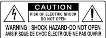
WARNING: There are no user serviceable parts inside. Refer all servicing to qualified service personnel.
WARNING: To reduce the risk of fire or electric shock, do not expose the unit to moisture or water. Do not expose the unit to dripping or splashing. Do not place objects filled with liquids, such as vases, on the unit. Do not allow foreign objects to get into the enclosure. If the unit is exposed to moisture, or a foreign object gets into the enclosure, immediately disconnect the power cord from the wall. Take the unit to a qualified service person for inspection and necessary repairs.
Read these instructions.
Keep these instructions.
Heed all warnings.
Follow all instructions.
Do not use this apparatus near water.
Clean only with dry cloth.
Do not block any ventilation openings. Install in accordance with the manufacturer's instructions.
Do not install near any heat sources such as radiators, heat registers, stoves, or other apparatus (including amplifiers) that produce heat.
Do not defeat the safety purpose of the polarized or grounding-type plug. A polarized plug has two blades with one wider than the other. A grounding type plug has two blades and a third grounding prong. The wide blade or the third prong are provided for your safety. If the provided plug does not fit into your outlet, consult an electrician for replacement of the obsolete outlet.
Protect the power cord from being walked on or pinched particularly at plugs, convenience receptacles, and the point where they exit from the apparatus.
Only use attachments/accessories specified by the manufacturer.
Use only with the cart, stand, tripod, bracket, or table specified by the manufacturer, or sold with the apparatus. When a cart is used, use with caution when moving the cart/apparatus combination to avoid injury from tip-over.

Unplug this apparatus during lightning storms or when unused for long periods of time.
Refer all servicing to qualified service personnel. Servicing is required when the apparatus has been damaged in any way, such as power-supply cord or plug is damaged, liquid has been spilled or objects have fallen into the apparatus, the apparatus has been exposed to rain or moisture, does not operate normally, or has been dropped.
The apparatus should be used in non tropical climate.
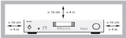
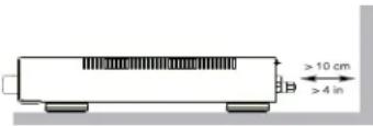
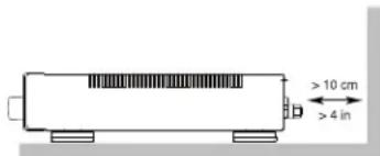
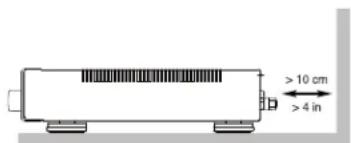
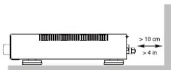
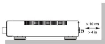
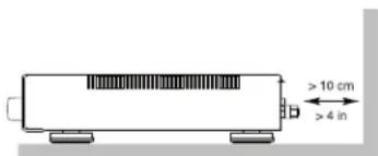
You must allow a minimum 10 cm or 4 inches of unobstructed clearance around the unit.
WARNING: The rear panel power cord connector is the mains power disconnect device. The device must be located in an open area that allows access to the cord connector.
The unit must be connected to a power supply only of the type and voltage specified on the rear panel. (USA: 120 V/60Hz, EC: 230V/50Hz) Connect the component to the power outlet only with the supplied power supply cable or an exact equivalent. Do not modify the supplied cable. Do not use extension cords.
The mains plug is the disconnect of the unit. In order to completely disconnect the unit from the supply mains, remove the main plug from the unit and the AC power outlet. This is the only way to completely remove mains power from the unit.
Use Class 2 wiring for speaker connections to ensure proper installation and minimize the risk of electrical shock.
The batteries in the remote control should not be exposed to excessive temperature such as sunshine, fire or other heat sources. Batteries should be recycled or disposed as per state and local guidelines.
APPLICABLE FOR USA, CANADA OR WHERE APPROVED FOR THE USAGE
CAUTION: TO PREVENT ELECTRIC SHOCK, MATCH WIDE BLADE OF PLUG TO WIDE SLOT, INSERT FULLY.
ATTENTION: POUR EVITER LES CHOCS ELECTRIQUES, INTRODUIRE LA LAME LA PLUS LARGE DE LA FICHE DANS LA BORNE CORRESPONDANTE DE LA PRISE ET POUSSER JUSQU AU FOND.
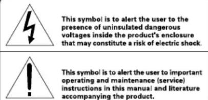

Rotel products are designed to comply with international directives on the Restriction of Hazardous Substances (RoHS) in electrical and electronic equipment and the disposal of Waste Electrical and Electronic Equipment (WEEE). The crossed wheelie bin symbol indicates compliance and that the products must be appropriately recycled or processed in accordance with these directives.
This symbol means that this unit is double insulated. An earth connection is not required.


Figure 1: Controls and Connections
Figure 3: Preamp Input and Speaker Output Connections
Branchements des entrées sources et sorties enceintes acoustiques Anschlussdiagramm Conexiones para Entrada de Señal y Salida a las Cajas Acústicas Collegamenti ingressi e diffusori De signaalingangen en de luidsprekeruitgangen Signal- och högtalaranslutningar Подсоединение источников сигнала и акустических систем
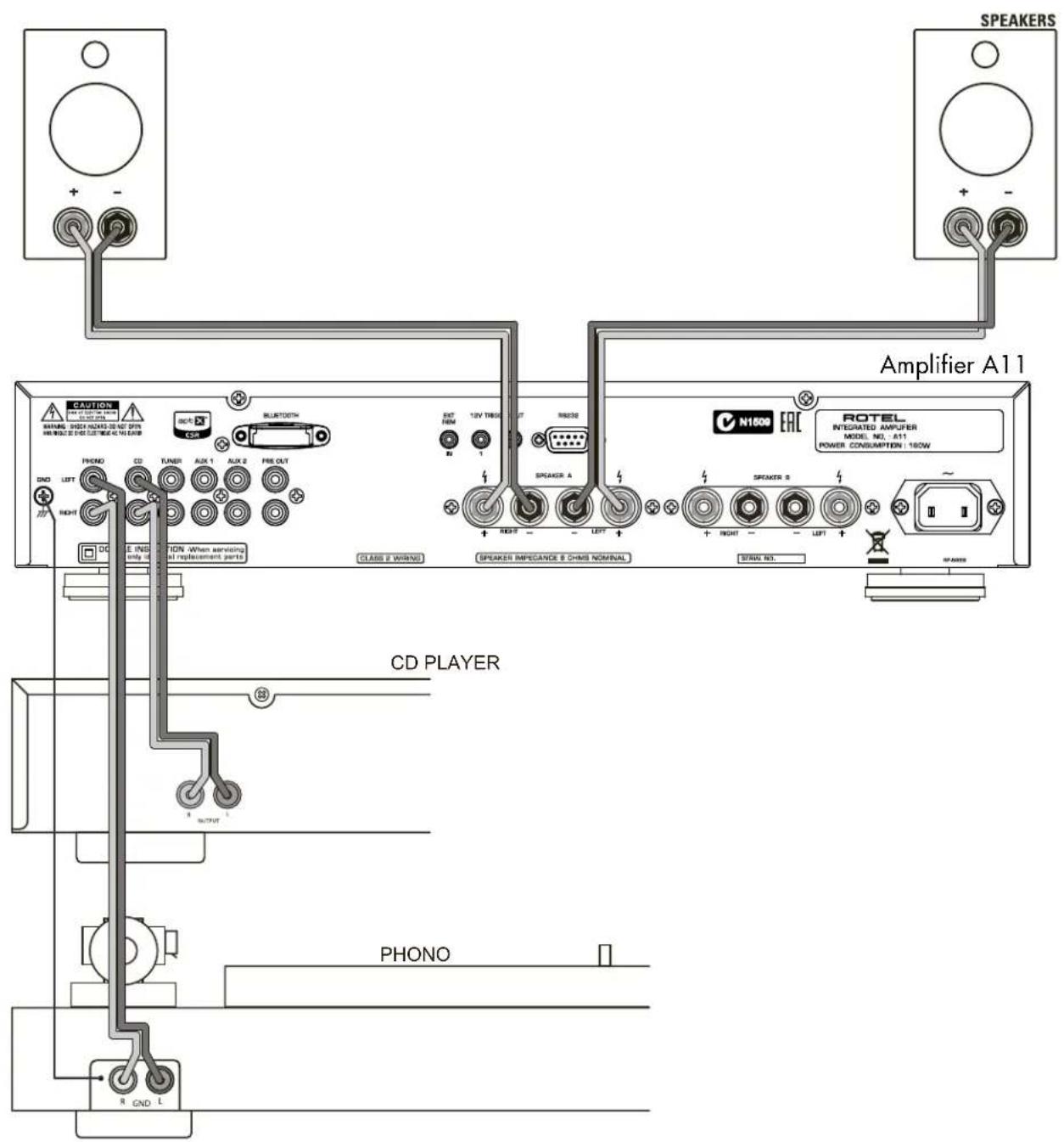
Figure 4: 12V Trigger Connections
Branchements trigger 12 V
12V-Trigger-Anschlüsse
When making connections be sure to:
√ Turn off all the components in the system before hooking up any components, including loudspeakers.
√ Turn off all components in the system before changing any of the connections to the system.
It is also recommended that you:
√ Turn the volume control of the amplifier all the way down before the amplifier is turned on or off.
Remarques importantes
Important Safety Instructions 2
Figure 1: Controls and Connections 3
Figure 2: Remote Control RR-AX1401 4
Figure 3: Preamp Input and Speaker Output Connections 5
Figure 4: 12V Trigger Connections 6
Important Notes 7
About Rotel....8
Getting Started 8
A Few Precautions 9
Placement 9
Cables 9
The RR-AX1401 Remote Control....9
Remote Control Batteries 9
AC Power and Control 9
AC Power Input 9
Power Switch 1 (A) and Power Indicator 2 9
12V Trigger Connection 9
Protection Indicator 2....10
Input Signal Connections 10
Phono Input □ and Ground Connection (GND) □ 10
Line Level Inputs 11 12 17 10
Preamp Output 10 10
Speaker Outputs 19 20 10
Speaker Selector Switch 10
Speaker Selection 10
Speaker Wire Selection 10
Polarity and Phasing 10
Speaker Connection 10
Headphone Output 3 11
Display 11
APTX Bluetooth Connection 13 11
Audio Controls....11
Volume Control B E 11
Balance Control B 11
Source Input Selector 7 ① 11
Tone Control 11
Tone Bypass 11
Tone Enabled 11
Tone Rotel Boost 11
Tone Rotel Max 11
Bass and Treble Controls ☐⑧ 12
Dimmer Control 12
Display Dimmer ☐① 12
LED Dimmer 12
EXT REM IN Jack 14 12
RS232 Connector 16 12
Settings Menu 12
Troubleshooting....13
Power Indicator Is Not Illuminated 13
Fuse Replacement 13
No Sound 13
playable Audio Formats 13
Cannot Connect via Bluetooth 13
Specifications....14
About Rotel
Our story began over 50 years ago. Over the decades, we have received hundreds of awards for our products and satisfied hundreds of thousands of people who take their entertainment seriously – like you.
Rotel was founded by a family whose passionate interest in music led them to manufacture high-fidelity components of uncompromising quality.
Through the years, that passion has remained undiminished and the family goal of providing exceptional value for audiophiles and music lovers, regardless of their budget, is shared by all Rotel employees.
Rotel's engineers work as a close team, listening to, and fine tuning, each new product until it reaches their exacting musical standards. They are free to choose components from around the world in order to make that product the best they can. You are likely to find capacitors from the United Kingdom and Germany, semiconductors from Japan or the United States, while toroidal power transformers are manufactured in Rotel's own factory.
We all have concerns about our environment. And, as more and more electronics are produced it is especially important for a manufacturer to do all it can to engineer products that have a minimum impact on the environment.
At Rotel, we are proud to do our part. We have reduced the lead content in our products by using special lead-free ROHS solder and components. Our engineers continually strive to improve power supply efficiency without compromise to quality. When in standby mode Rotel products use minimal power to meet global Standby Power Consumption requirements.
The Rotel factory is also doing their part to help the environment through constant improvements to product assembly methods for a cleaner and greener manufacturing processes.
All of us at Rotel thank you for buying this product. We are sure it will bring you many years of enjoyment.
Getting Started
Thank you for purchasing the Rotel A11 Stereo Integrated Amplifier. When used in a high-quality music audio system, Rotel products will provide years of musical enjoyment.
This amplifier is a full featured, high performance component. All aspects of the design have been optimized to retain the full dynamic range and subtle nuances of your music. The un it has a highly regulated power supply incorporating a Rotel custom-designed toroidal power transformer. This low impedance power supply has ample power reserves, which enables the amplifier to easily reproduce the most demanding audio signals. This type of design is more expensive to manufacture, but it is better for the music.
The printed circuit boards (PCB) are designed with Symmetrical Circuit Traces. This ensures that the precise timing of the music is maintained and faithfully recreated. The circuitry uses metal film resistors and polystyrene or polypropylene capacitors in important signal paths. All aspects of this design have been examined to ensure the most faithful music reproduction.
The main functions of the A11 are easy to install and use. If you have experience with other stereo systems, you shouldn't find anything perplexing. Simply plug in the associated components and enjoy.
A Few Precautions
WARNING: To avoid potential damage to your system, turn off ALL the components in the system when connecting or disconnecting the loudspeakers or any associated components. Do not turn the system components back on until you are sure all the connections are correct and secure. Pay particular attention to the speaker wires. There must be no loose strands that could contact the other speaker wires, or the chassis of the amplifier.
Please read this manual carefully. It provides information on how to incorporate the unit into your system as well as information that will help you get optimum sound performance. Please contact your authorized Rotel dealer for answers to any questions you might have. In addition, all of us at Rotel welcome your questions and comments.
Save the shipping carton and all enclosed packing material for future use. Shipping or moving the amplifier in anything other than the original packing material may result in severe damage to your amplifier.
If included in the box please fill out and send in the owner's registration card. Also be sure to keep the original sales receipt. It is your best record of the date of purchase, which you will need in the event warranty service is ever required.
Placement
Like all audio components that handle low level signals, this amplifier can be affected by its environment. Avoid placing the unit on top of other components. Also avoid routing audio signal cables near power cords. This will minimize the chance it will pick up hum or interference.
The unit generates heat as part of its normal operation. The heat sinks and ventilation openings in the amplifier are designed to dissipate this heat. The ventilation slots in the top cover must be open. There should be 10 cm (4 inches) of clearance around the chassis, and reasonable airflow through the installation location, to prevent the amplifier from overheating.
Remember the weight of the amplifier when you select an installation location. Make sure that the shelf or cabinet can support it. We recommend installing the unit in furniture designed to house audio components. Such furniture is designed to reduce or suppress vibration which can adversely affect sound quality. Ask your authorized Rotel dealer for advice about component furniture and proper installation of audio components.
Cables
Be sure to keep the power cords, digital signal cables and analog audio signal cables in your installation away from each other. This will minimize the chance of the analog audio signal cables picking up noise or interference from the power cords or digital cables. Using only high quality, shielded cables will also help to prevent noise or interference from degrading the sound quality of your system. If you have any questions see your authorized Rotel dealer for advice about the best cable to use with your system.
The RR-AX1401 Remote Control
Some functions can be done with either the front panel controls, or the supplied RR-AX1401 remote control. When these operations are described, the square call out numbers refer to the main unit, while the encircled letters refer to the remote control.
Remote Control Batteries
Two AAA size batteries (supplied) must be installed before the remote control can be used. To install the batteries, remove the cover on the back of the RR-AX1401. Install the batteries as shown in the illustration in the battery well. Test the control for proper operation, then replace the cover. When the batteries become weak the remote control won't operate the A11 consistently. Installing fresh batteries should eliminate the problem.
AC Power and Control
AC Power Input 21
Your unit is configured at the factory for the proper AC line voltage in the country where you purchased it (either 120 volts AC or 230 volts AC with a line frequency of either 50 Hz or 60 Hz). The AC line configuration is noted on a decal on the back panel.
NOTE: Should you move your amplifier to another country, it is possible to reconfigure it for use on a different line voltage. Do not attempt to perform this conversion yourself. Opening the enclosure of the unit exposes you to dangerous voltages. Consult a qualified service person or the Rotel factory service department for information.
NOTE: Some products are intended for sale in more than one country and as such are supplied with more than one AC cord. Please only use the one appropriate for your country/region.
The unit does not draw high levels of current from the power outlet. However, it should be plugged directly into a polarized wall outlet using the supplied cable or other compatible cable as recommended by your authorized Rotel dealer. Do not use an extension cord. A heavy duty multi-tap power outlet strip may be used if it (and the wall outlet) can handle the current demanded by the amplifier and all the other components connected to it.
If you are going to be away from home for an extended period of time such as a month-long vacation, it is a sensible precaution to unplug your amplifier (as well as other audio and video components) while you are away.
Power Switch 1① and Power Indicator 2
Press the front panel Power Switch button 1 to turn the unit on. The Power Indicator light 2 is illuminated when the unit is on. Press Power Switch button again to turn the unit off.
When the power switch is in the ON position, the remote control ON and OFF buttons may be used to activate the A11. In Standby mode the power LED is red, but the display is turned OFF.
12V Trigger Connection 15
See Figure 4
Some audio components can be turned on automatically when they receive a 12V turn on signal. The two 12V Trigger Outputs of the A11 unit provide the required signal. Connect compatible components to the amplifier with a conventional 3.5mm mini plug cable. When the unit is in standby mode or turned off, the trigger signal is interrupted, and the components controlled by it are turned off.
Protection Indicator z
The amplifier has both thermal and over-current protection circuitry that protects the amplifier against damage in the event of extreme or faulty operating conditions. The protection circuits are independent of the audio signal and have no impact on sonic performance. Instead, the protection circuits monitor the temperature of the output devices and shut down the amplifier if temperatures exceed safe limits.
Most likely, you will never see this protection circuitry in action. However, should a faulty condition arise, the amplifier will stop playing and will display "AMP PROTECTION" on the front panel. The power indicator 2 on the front panel will turn red.
If this happens, turn the amplifier off. Let it cool down for several minutes, and attempt to identify and correct the problem that caused the protection circuitry to engage. When you turn the amplifier back on, the protection circuit will automatically reset and the power indicator 2 should turn blue.
In most cases, the protection circuitry activates because of a fault condition such as shorted speaker wires, or inadequate ventilation leading to an overheating condition. In very rare cases, highly reactive or extremely low impedance speaker loads could cause the protection circuit to engage.
If the protection circuitry triggers repeatedly and you are unable to isolate and correct the faulty condition, contact your authorized Rotel dealer for assistance in troubleshooting.
Input Signal Connections
See Figure 3
NOTE: To prevent loud noises that neither you nor your speakers will appreciate, make sure the system is turned off when you make any signal connections.
Phono Input 10 and Ground Connection (GND) 9
Plug the cable from the turntable into the appropriate left and right phono inputs. If the turntable has a "ground" wire, connect it to the screw terminal to the left of the Phono inputs. It will help prevent hum and noise.
Line Level Inputs 11 12 17
The CD, Tuner, and Aux inputs of the amplifier are "line level" inputs. These are for connecting components such as CD players or other audio playback devices with an analog audio output.
The Left and Right channels are labeled and should be connected to the corresponding channels of the source component. The Left connectors are white, the Right connectors are red. Use high quality RCA cables for connecting input source components to the unit. Ask your authorized Rotel dealer for advice about cables.
Preamp Output 18
The amplifier has a set of preamp outputs labeled PRE OUT. The currently selected source input is available from this output. Typically the PRE OUT output is used to provide a signal to another integrated amplifier or power amplifier, which is used to drive remote speakers.
NOTE: Changes to the settings of the Volume, Balance or Tone controls affect the signal from the Preamp Output.
Speaker Outputs 19 20
See Figure 3
Speaker Selector Switch 4
The amplifier has two sets of speaker outputs, labeled "SPEAKER A" 19 and "SPEAKER B" 20. The speaker outputs are controlled by the A-B speaker selector buttons 4 on the front panel or 1 on the remote control.
Speaker Selection
If only one set of speakers will be used at any given time, the speakers may have an impedance as low as 4 ohms. If there are times when both the A and B speakers will be used, all the speakers should have an impedance of 8 ohms or more. Speaker impedance ratings are less than precise. In practice, very few loudspeakers will present any problems for the unit. See your authorized Rotel dealer if you have any questions.
Speaker Wire Selection
Use insulated two-conductor stranded wire to connect the unit to the speakers. The size and quality of the wire can have an audible effect on the performance of the system. Standard speaker wire will work, but can result in lower output or diminished bass response, particularly over longer distances. In general, heavier wire will improve the sound. For best performance, you may want to consider special high-quality speaker cables. Your authorized Rotel dealer can help in the selection of cables for your system.
Polarity and Phasing
The polarity - the positive/negative orientation of the connections - for every speaker and amplifier connection must be consistent so all the speakers will be in phase. If the polarity of one connection is reversed, bass output will be very weak and stereo imaging degraded. All wire is marked so you can identify the two conductors. There may be ribs or a stripe on the insulation of one conductor. The wire may have clear insulation with different color conductors (copper and silver). There may be polarity indications printed on the insulation. Identify the positive and negative conductors and be consistent with every speaker and amplifier connection.
Speaker Connection
Turn off all the components in the system before connecting the speakers. The amplifier has color-coded binding post type speaker connectors on the back panel. These connectors accept bare wire, connector lugs, or dual banana type connectors. (Except in European Community countries where their use is not permitted.)
Route the wire from the amplifier to the speakers. Give yourself enough slack so you can move the components to allow access to the speaker connectors. If you are using dual banana plugs, connect them to the wires and then plug into the backs of the binding posts. The thumbscrews of the binding posts should be screwed in all the way (clockwise).
If you are using terminal lugs, connect them to the wires. If you are attaching bare wires directly to the binding posts, separate the wire conductors and strip the insulation from the end of each conductor. Be careful not to cut into the wire strands. Unscrew (turn counterclockwise) the binding post thumbscrews. Place the connector lug or wire around the binding post shaft. Turn the thumbscrews clockwise to clamp the connector lug or wire firmly in place.
NOTE: Be sure there are no loose wire strands that could touch adjacent wires or connectors.
Headphone Output 3
The headphone output allows you to connect headphones for private listening. This output accepts a standard 3.5mm (1/8") mini stereo headphone connector. Plugging in a set of headphones does not cut off the signal to the speakers. Use the front panel 4 or remote control ① A-B speaker selector buttons to turn off the speakers.
NOTE: Because the sensitivity of speakers and headphones can vary widely, always reduce the volume level before connecting or disconnecting headphones.
Display 5
The front panel display shows the source selected, volume level and tone settings. The display provides access to the setup and configuration menu options of the amplifier.
APTX Bluetooth Connection 13
The Bluetooth Antenna ^13 on the unit's back panel is for wireless streaming via Bluetooth, from your device (i.e. mobile phones, tablets or computers). From your device, look for "Rotel Bluetooth" and connect to it. Connection is normally automatic, but if prompted for a password, please enter "0000" on your device. The unit supports both traditional Bluetooth and APTX Bluetooth audio streaming.
Audio Controls
Volume Control ☐⑥
Turn the control clockwise to increase the volume, or counter clockwise to decrease the volume. From the remote control press the volume + or - button to turn the volume up or down. Press the MUTE ⑤ button to completely mute the volume.
Balance Control ☐⑧
The Balance Control adjusts the left-to-right balance of the sound output. The factory default is the center position or "0". To change the balance from the front panel, press the MENU ☐ button to toggle the front display to BALANCE SETTING mode. Then press the - or + buttons on the front panel to change the value to LEFT or RIGHT. The value can change from L15 to R15.
NOTE: This setting is saved permanently including after powering off the A11.
To make temporary changes not saved after power off, from the remote, press the BAL® button to access the BALANCE SETTING menu, then press the up/down/left/right © arrow buttons to adjust.
Source Input Selector 7 ①
Press the corresponding input button on the front panel 7 or remote control ① to select the desired listening source.
Tone Control
The A11 features 4 different Tone Control options to provide a wide array of listening options. The options include a BYPASS mode that disables the Bass and Treble controls for the most direct audio path, ENABLED mode that allows user selectable Bass and Treble settings and ROTEL BOOST and ROTEL MAX modes supporting optimized configurations for multiple listening environments and styles.
The factory default option is set to BYPASS to provide the purest possible sound. The tone settings can be changed using the IR remote control or the front panel.
To temporarily change the Tone Control push the BYPASS® button on the remote control to cycle through the 4 different modes. When Tone Enabled is selected the Bass and Treble settings can be changed using the remote control by pressing the BASS or TREB ® buttons then pressing the up/down/left/right © arrow buttons on the remote to adjust the value. The BYPASS, ROTEL BOOST and ROTEL MAX settings do not allow changes to the Bass and Treble settings.
NOTE: These settings are temporary and are not saved after the A11 is powered off or in standby mode.
The Tone Control setting can be saved permanently (even after power off) using the front panel setup menu. A description of the Tone Modes and setup process is listed below.
Tone Bypass
Bass and Treble Controls are not active to ensure the purest possible sound. To select this option press the front panel ☐ or IR remote MENU Ⓚ button repeatedly to toggle to the Tone Setup menu. Then press the - or + buttons to select the BYPASS mode. This mode is the factory default option.
Tone Enabled
When the Tone Enabled option is selected the Bass and Treble levels can be changed using the BASS Ⓑ or TREB Ⓑ buttons on the IR remote control and pressing the up/down/left/right ⓒ arrow buttons to adjust the value. To select this option press the front panel Ⓑ or IR remote MENU Ⓕ button repeatedly to toggle to the Tone Setup menu then press the - or + buttons to select the ENABLED mode.
NOTE: Be particularly careful when turning the tone controls up. This increases the power output in the bass or treble range increasing the load on the amplifier and speakers.
Tone Rotel Boost
The Rotel Boost mode is unique to Rotel and delivers a customized listening experience. The audio performance is "boosted" and delivers a unique blend of tonal characteristics. To select this option press the front panel or IR remote MENU button repeatedly to toggle to the Tone Setup menu then press the - or + buttons to select the ROTEL BOOST mode.
Tone Rotel Max
Rotel Max increases the low frequency output to deliver more bass. This feature is ideal for music, listening environments or speakers that benefit from more bass while still maintaining the tones of the vocal and midrange frequencies. To select this option press the front panel ☐ or IR remote MENU Ⓚ button repeatedly to toggle to the to the Tone Setup menu then press the - or + buttons to select the ROTEL MAX mode.
NOTE: The setup menu Tone Setting is saved permanently including after powering off the A11.
Bass and Treble Controls ☐ B
When Tone Control is set to ENABLED the Bass and Treble levels can be configured in the setup menu. These settings are saved permanently including after Power Off or when the unit is in Standby. To set the Bass or Treble levels press the front panel B or IR remote MENU K button repeatedly to toggle to the Bass or Treble Setting menu then press the - or + buttons to adjust the value. The Bass and Treble values range from -10 to +10.
NOTE: The setup menu Bass and Treble settings are saved permanently including after powering off the A11.
To temporarily change the Bass and Treble settings from the remote control, press the BASS or TREB Ⓑ button, then press the up/down/left/right Ⓒ arrow buttons on the remote to adjust the value.
NOTE: Bass and Treble changes are only available when Tone Enabled is selected (see Tone Enabled section).
A properly setup high-performance audio system produces the most natural sound with little or no adjustment of the tone controls. Use these controls sparingly.
Dimmer Control
Display Dimmer ☐ D
To change the brightness of the front display, press the MENU button to toggle to the DIMMER Setting. Then press the - or + buttons on the front panel to change the display brightness.
NOTE: This setting is saved permanently including after powering off the A11.
To temporarily change the display brightness, press the DIM ① button on the remote.
LED Dimmer ☐
To change the brightness of the Power LED and the two Speaker Selector LEDs on the front panel, press the MENU [8] button to toggle to the LED DIMMER Setting. Then press the - or + buttons on the front panel to change the LEDs brightness.
NOTE: This setting is saved permanently including after powering off the A11.
EXT REM IN Jack 14
This 3.5mm mini-jack receives command codes from industry-standard infrared receivers via hard-wired connections. This feature could prove useful when the unit is installed in a cabinet and the front-panel sensor is blocked. Consult your authorized Rotel dealer for information on these external repeaters and the proper wiring of a jack to fit the mini-jack receptacle.
RS232 Connector 16
The A11 can be controlled via RS232 for integration with automation systems. The RS232 input accepts a standard straight DB-9 Male-to-Female cable.
For additional information on the connections, software, and operating codes for RS232 control of the A11, contact your authorized Rotel dealer.
Settings Menu
You can access the SETUP menu from the front panel by pressing the MENU ☐ button or the Ⓚ button on the remote. You can change the value of the selected option by pressing the - or + buttons on the front panel or the up/down/left/right Ⓒ arrow buttons on the remote. Step through the sub-menus by pressing the MENU ☐ button on the front panel or the Ⓚ button on the remote.
- TONE: TONE setting can be changed to BYPASS, ENABLED, ROTEL BOOST, ROTEL MAX. (For more information refer to Tone Control section.)
NOTE: This setting is stored permanently even after the A11 is powered off.
- BASS: BASS level can be changed to desired settings. (For more information refer to Bass and Treble Control section.)
NOTE: This setting is stored permanently even after the A11 is powered off.
- TREBLE: TREBLE level can be changed to desired settings. (For more information refer to Bass and Treble Control section.)
NOTE: This setting is stored permanently even after the A11 is powered off.
- BALANCE: Change left/right balance. (For more information refer to Balance Control section.)
NOTE: This settings is stored permanently even after the A11 is powered off.
• DIMMER: Dims the front display.
NOTE: This setting is stored permanently even after the A11 is powered off.
- LED DIMMER: Dims the Power LED and the LEDs above the Speaker Selector buttons on the front panel.
NOTE: This setting is stored permanently even after the A11 is powered off.
- POWER ON MAX VOL: This sets the maximum volume level when the unit is turned on. "45" is the factory default.
NOTE: Power On Max Volume settings do not apply to sources configured with Fixed Gain.
- OFF TIMER: The A11 can be configured to automatically power off if unused for a specified period. If no changes are made to the unit within
the specified "Off Timer" period the unit will automatically go to STANDBY mode. The Auto Power Off timer will be restarted if changes are made to the volume, source or playback. The default for Off Timer is set to 20 MINS.
Valid settings include: DISABLE, 20 MINS, 1 HOUR, 2 HOURS, 5 HOURS, 12 HOURS.
- SIGNAL SENSE: Check if a audio signal is present on the configured Signal Sense input. The A11 monitors the data stream to determine if there is audio. If there is no audio detected for 10 minutes, the A11 will enter Signal Sense Power Mode. When in Signal Sense Power Mode and the A11 detects audio on Signal Sense input, the unit will automatically power on. To disable this function, select the OFF option which is the factory default setting.
NOTE: When the A11 enters standby mode via the remote control, the Signal Sense function will not operate until the unit detects the audio has stopped for the minimum 10 minute time-out period. This prevents the unit from immediately powering back on if there is still active audio playing.
NOTE: When the SIGNAL SENSE function is activated the A11 will consume additional power in Signal Sense Power mode.
- FIXED GAIN: Configures a Fixed Volume level for a specified input. To enable this feature, select the desired fixed volume level for AUX1, AUX2 or Bluetooth. When enabled and the input with a Fixed Volume is selected, the Volume level will immediately be set to the specified level.
Valid settings include: VARIABLE, FIXED MIN, FIXED 01-95, FIXED MAX.
- AUX1 VOL: VARIABLE (disabled) is factory default.
- AUX2 VOL: VARIABLE (disabled) is factory default.
- BTOOTH VOL: VARIABLE (disabled) is factory default.
NOTE: The Volume knob on the front panel and Volume +/- buttons on the IR remote are disabled when the volume is Fixed. To disable this feature set the Fixed Volume level to "Variable".
- S/W VERSION: This shows the current software version loaded into the amplifier.
- FACTORY RESET: This sets the unit back to the original state as when it left the factory. Press the + button on the front panel or the ENT button on the remote control to enter factory reset setting. And then press the + button or ENT again to begin reset, or press the MENU button to cancel.
NOTE: All previously configured options will be erased and reset to the factory default settings.
Troubleshooting
Most difficulties in audio systems are the result of incorrect connections, or improper control settings. If you encounter problems, isolate the area of the difficulty, check the control settings, determine the cause of the fault and make the necessary changes. If you are unable to get sound from the unit, refer to the suggestions for the following conditions:
Power Indicator Is Not Illuminated
The Power Indicator and the basic items in the Display window should be illuminated whenever the unit is plugged into the wall power outlet and the Power button is pushed in. If it does not illuminated, test the power outlet with another electrical device, such as a lamp. Be sure the power outlet being used is not controlled by a switch that has been turned off.
Fuse Replacement
If another electrical device works when plugged into the power outlet, but the Power Indicator still will not illuminated when the unit is plugged into the wall outlet, it indicates that the internal power fuse may have blown. If you believe this has happened, contact your authorized Rotel dealer to get the fuse replaced.
No Sound
Check the signal source to see if it is functioning properly. Make sure the cables from the signal source to the amplifier inputs are connected properly. Be sure the Input Source is set to the proper input. Check the wiring between the amplifier and the speakers.
playable Audio Formats
APTX Bluetooth
| Format Notes | |
| Any format supported by the sending device. | May exclude Apps designed to play formats not originally supported by the sending device. |
Cannot Connect via Bluetooth
If you cannot pair your Bluetooth enabled device to the A11, delete the memory of the previous connection on your device. On your device this is often listed as "Forget this Device". Then try to make the connection again.
Specifications
Continuous Power Output 50 watts/ch
(20 - 20kHz, < 0.03%, 8 ohms)
Total Harmonic Distortion (20 Hz - 20k Hz, 8 ohms) < 0.03%
Intermodulation Distortion (60 Hz : 7k Hz, 4:1) < 0.03%
Frequency Response
Phono Input 20 Hz - 20k Hz, ± 0.5 dB
Line Level Inputs 10 Hz - 100k Hz, ± 0.5 dB
Damping Factor (20 - 20,000 Hz, 8 ohms) 140
Input Sensitivity / Impedance
Phono Input 2.3 mV / 47k Ohms
Line Level Inputs 180 mV / 47k Ohms
Input Overload
Phono Input 50 mV
Line Level Inputs 4 V
Preamp Output / Impedance 1 V / 470 Ohms
Tone Controls - Boss // Trebble ± 10 dB at 100 Hz / 10k Hz
Signal to Noise Ratio (A weighting)
Phono Input 85 dB
Line Level Inputs 100 dB
General
Power Requirements
USA 120V, 60 Hz
EC 230V, 50 Hz
Standby Power Consumption < 0.5W
Power Consumption 160 Watts
BTU (4 ohms, 1/8th power) 479 BTU/h
Dimensions (W, H, D) 430 x 93 x 345 mm
$$ 1 7 ^ {\prime \prime} \times 3 ^ {5 / 8 ^ {\prime \prime}} \times 1 3 ^ {1 / 2 ^ {\prime \prime}} $$
Panel Height
80 mm / 3 1/8".
Weight (net)
6.85 kg, 15.1 lbs.
All specifications are accurate at the time of printing.
Rotel reserves the right to make improvements without notice.
Rotel and the Rotel HiFi logo are registered trademarks of The Rotel Co., Ltd.
Tokyo, Japan.
Figure 4: Branchements trigger 12 V 6
Remarques importantes 7
Distorsion harmonique totale <0.03%,
(20Hz-20kHz, 8 ohms)
Distorsion d'intermodulation (60 Hz : 7 kHz, 4 : 1) < 0.03%
Höhe Frontpanel 80 mm
Controlli audio....53
Volume 5 E 53
Bilanciamento ☐ B 53
Controlli tone....53
Tone Bypass 54
Tone Enabled 54
Tone Rotel Boost 54
Tone Rotel Max 54
2-11-4, Nakane, Meguro-ku,
Tokyo, 152-0031
Japan
Rotel of America
54 Concord Street
North Reading, MA 01864-2699
USA
Phone: +1 978-664-3820
Fax: +1 978-664-4109
Rotel Europe
Dale Road
Worthing, West Sussex BN11 2BH
England
Phone: + 44 (0)1903 221 763
Fax: +44 (0)1903 221 525
Rotel Deutschland
- Important Safety Instructions
- Notice
- APPLICABLE FOR USA, CANADA OR WHERE APPROVED FOR THE USAGE
- When making connections be sure to:
- It is also recommended that you:
- Remarques importantes
- About Rotel
- Getting Started
- A Few Precautions
- Placement
- Cables
- The RR-AX1401 Remote Control
- Remote Control Batteries
- AC Power and Control
- AC Power Input 21
- Power Switch 1① and Power Indicator 2
- 12V Trigger Connection 15
- Protection Indicator z
- Input Signal Connections
- Phono Input 10 and Ground Connection (GND) 9
- Line Level Inputs 11 12 17
- Preamp Output 18
- Speaker Outputs 19 20
- Speaker Selector Switch 4
- Speaker Selection
- Speaker Wire Selection
- Polarity and Phasing
- Speaker Connection
- Headphone Output 3
- Display 5
- APTX Bluetooth Connection 13
- Audio Controls
- Volume Control ☐⑥
- Balance Control ☐⑧
- Source Input Selector 7 ①
- Tone Control
- Tone Bypass
- Tone Enabled
- Tone Rotel Boost
- Tone Rotel Max
- Bass and Treble Controls ☐ B
- Dimmer Control
- Display Dimmer ☐ D
- LED Dimmer ☐
- EXT REM IN Jack 14
- RS232 Connector 16
- Settings Menu
- Troubleshooting
- Power Indicator Is Not Illuminated
- Fuse Replacement
- No Sound
- playable Audio Formats
- Cannot Connect via Bluetooth
- Specifications
- Frequency Response
- Input Sensitivity / Impedance
- Input Overload
- General
- Power Requirements
- Rotel of America
- Rotel Europe
- Rotel Deutschland
Brand : ROTEL
Model : A11
Category : Receiver