DN108LF - Pregnant DENON - Free user manual and instructions
Find the device manual for free DN108LF DENON in PDF.
User questions about DN108LF DENON
0 question about this device. Answer the ones you know or ask your own.
Ask a new question about this device
Download the instructions for your Pregnant in PDF format for free! Find your manual DN108LF - DENON and take your electronic device back in hand. On this page are published all the documents necessary for the use of your device. DN108LF by DENON.
USER MANUAL DN108LF DENON
User Guide (English)
Introduction
The Denon Professional DN-108LF ceiling subwoofer is designed to deliver exceptionally accurate, articulate sound while easily meeting commercial requirements for fire-resistance and suitability for multiple unit installation.
It features a metal "can" rear enclosure, which provides a fire barrier behind the subwoofer to meet local commercial fire codes. It also serves as the woofer's enclosure to optimize its bass tuning and low frequency response. The subwoofer has 70/100-volt transformers to facilitate multiple unit installations without the impedance and level-matching concerns of paralleled transformerless subwooers.
The DN-108LF uses a long-excursion 8" (203 mm) non-press paper cone woofer for accurate and powerful low-frequency reproduction.
These high quality drive units in a tuned reflex enclosure with a precision passive crossover deliver clean, detailed sound, perfect for music applications, public address demands and business/educational presentations, while meeting all safety and fire codes as required by commercial venues.
Speaker Break-In
Speakers require a break-in period before they can be safely operated at maximum volume levels. Proper break-in ensures that the moving parts of the speaker (the cone and cone suspension) are allowed to flex and soften, loosening the initial stiffness and allowing the speaker to move through its full intended range. After the break-in period, the speakers will produce richer sounding lows, warmer and smoother sounding mids, and cleaner highs.
The best way to break-in speakers is to play normal music at moderate volume levels. The amount of time required for speaker break-in varies based on the operating environment, but is typically between 50-80 hours. It will take somewhat longer in a cold or dry environment and a little less time in a warm or humid environment.
Note: The break-in period does not have to be continuous.
Speaker Wire Preparation
Before attempting to make any connections it is best to consider the location, get all of the necessary materials together, and then make all of the connections at once.
First, look at the back of your amplifier or receiver to determine what options it offers for making connections. Amplifiers and receivers typically employ either 5-way binding posts, spring-loaded terminals, or push terminals for the speaker connections.
A 5-way binding post can accept bare speaker wire, spade plugs, pin plugs, and banana plugs, while spring loaded terminals and push terminals can accept either bare speaker wire or pin plugs. Refer to the documentation that came with your amplifier or receiver to determine the maximum size/gauge speaker wire the speaker terminals can accept.
DN-205W features push terminals, which can accept pin plugs or bare wire up to 14 AWG. If your amplifier can accept it, you should use 14 AWG speaker wire. Using pin plugs is highly recommended as it is easier to connect, no risk of stray wire strands shorting the connections, allows for use of heavier gauge speaker wire in most cases, and is much easier to identify the polarity from a color coded ring on a plug then from a subtle marking along the length of a wire.
Because the speaker wires will be run through your walls/ceiling, you must use in-wall rated wire which is required by fire safety codes. This ensures that the wire jacket will not act as an accelerator in the event of a fire.
Rather than using fixed length speaker wires, it is best to get a roll and cut the wires to the length you will need them. This ensures that there is a minimum amount of excess wire. However, even if your amplifier is off-center, the lengths of wire used for each speaker pair should be identical. This keeps the impedance on each channel the same, which ensures that the volume levels, frequency ranges, and tonalities are identical. Any excess wire should be snaked back and forth, not coiled, to avoid creating an inductor/antenna for stray radio signals.
Before making the actual connections, cut each length of wire to size. Note the markings on the wire that differentiate between each conductor. Sometimes the marking clearly identifies a positive and negative side. Some common clearly positive and negative markings or identifiers are:
| Positive Negative | |
| Red | Black |
| Copper | Silver |
| +++ -- | |
In many cases, the mark is a single stripe on the jacket of one of the connectors. In this case the side with the stripe is generally considered the positive side, but it really does not matter as long as you are consistent and always use the stripe as positive or always use it as negative.
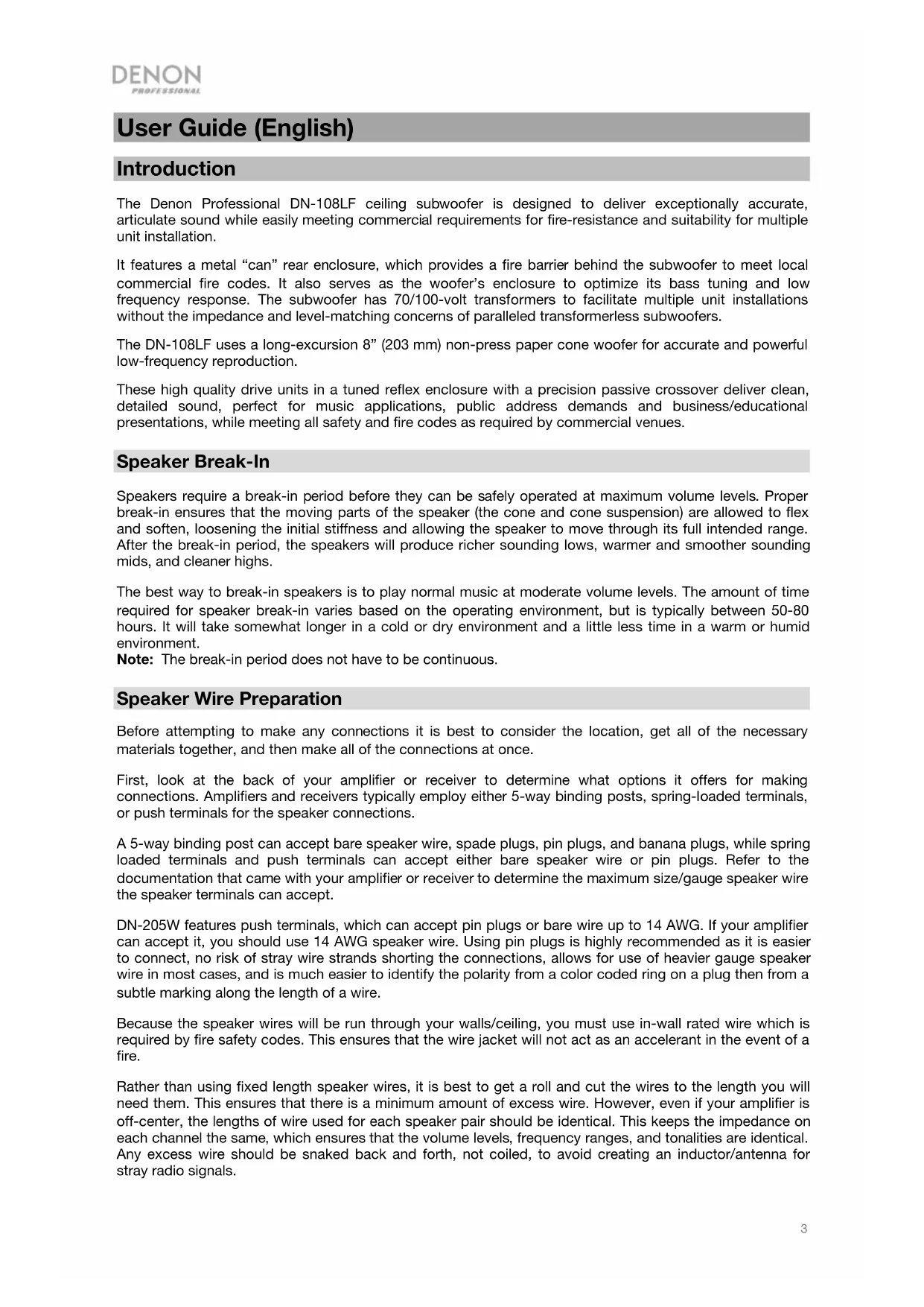
When you are ready to prepare your speaker wires, first separate about 4^ (101 mm) of wire, then strip about 1/4" (6 mm) insulation from the end and twist it to prevent stray strands. If you plan to use banana or pin plugs (highly recommended), install the plugs on the wire.
Painting
The grille and frame can be painted to match your walls or ceiling, making the speaker even less noticeable. Perform the following steps to safely paint without damaging the speaker.
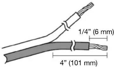
- Completely remove the grille by lifting the edge to pull it off the speaker body.
- Remove the felt matte from the back of the grille.
- Paint the speaker grille. It is best to use spray paint to avoid paint clogging the holes in the grille.
- Allow the paint to completely dry; then reattach the felt matte on the back of the grille.
- Before proceeding with the installation, ensure that the holes in the grille are not blocked by paint.
Box Contents
DN-108LF
Installation Template
Mounting Bracket
SubwooferGrille
(4) Screws
(4) Washers
4-Pin Euroblock Connector
User Guide
Safety/Warranty Manual
Support
For complete system requirements, compatibility information, and product registration, visit the Denon Professional website: denonpro.com.
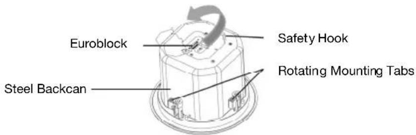
Subwoofer Diagram
Top Panel
Rear Panel
Installation
To ensure a reliable installation, please follow these steps carefully:
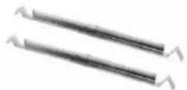
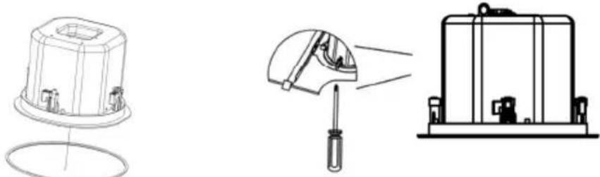
- Assemble the subwoofer mounting bracket (see graphic below) by taking one of the alignment beams and sticking it under the groove in the "C" shaped subwoofer mounting bracket. Place in the desired install location and use 2 screws and 2 washers to connect. Repeat this process on the other side while making sure the holes line up evenly.
- Determine the subwoofer position, taking into account any obstructions in the ceiling space. Note that a clearance of 8.7" (222 mm) above the lower face of the ceiling is required. The cutout diameter is 10.7" (273 mm).
- Remove the ceiling space and position the subwoofer mounting bracket so that the "C" shaped subwoofer mounting bracket fits the hole that you cut. Use a metal safety wire with a snap hook (sold separately) and loop it around a truss/beam on one end. Use a screw to mount the safety wire by fastening the subwoofer mounting bracket into the truss/beam that the safety wire is looped around. Make sure the screw head covers the surface area of the screw hole.
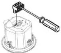
- Remove the supplied 4-pin Euroblock from the subwoofer and connect it to the subwoofer cable (see graphic below).
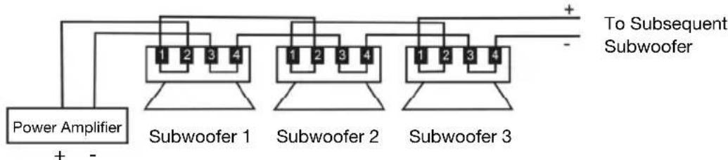
- Use the provided loop-through terminals (see graphic below). When this wiring method is used, you should be aware that when a subwoofer is not plugged in there is no path to subsequent subwoofer. An alternative is to wire incoming and outgoing cables in parallel. Pin 2 is + and Pin 3 is -
-
Insert the pre-wired Euroblock connector, ensuring the correct polarity is being used.
-
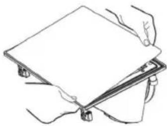
Begin to insert subwoofer into the "C" shaped subwoofer mounting bracket. Make sure to connect the snap hook to the safety hook on the back of the subwoofer. When the subwoofer is flush with the ceiling leaving only the black magnetic brim exposed, begin to tighten the 4 attachment screws which are connected to the mounting tabs (see graphics below). The screws will automatically turn once you begin rotating the screw clockwise. Repeat for all 4 tabs and make sure not to overtighten the screws.
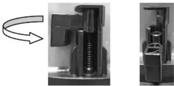
Note: Before you put the subwoofer into the ceiling, make sure all attachment screws are turned completely counter-clockwise so that the mounting tabs are touching the side of the steel backcan.
Note: Make sure to position the subwoofer so that the mounting tabs do not sit above the opening in the "C" shaped subwoofer mounting bracket.
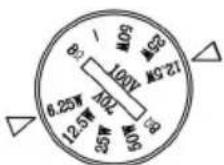
- Use a flat-head screwdriver to rotate the Tap Selector so that the correct power setting is adjacent to the arrow. Note that there are separate 70V and 100V scales, depending on the line voltage being used (see the graphic below). The transformer may also be bypassed by selecting the 8 ohm position. It may be best to leave the grill off until setting the power is complete in case adjustments are needed.
- Attach the magnetic grill on the subwoofer.
Assistance technique
Technical Specifications
| Low-Frequency Driver | 8” / 210 mm diameter woofer | |
| Power Tappings | W (100V) W (70V) | |
| - | 50 W | |
| 50 W 25 W | ||
| 25 W 12.5 W | ||
| 12.5 W 6.25 W | ||
| Bypass | 8 ohms 8 ohms | |
| Frequency Response | 53 Hz - 2.3 kHz | |
| Driver Power | 80 W (RMS) | |
| Sensitivity | 89 dB (1W/1m) | |
| Cutout Hole Diameter | 10.7” / 273 mm | |
| In-Ceiling Clearance Height | 8.7” / 222 mm | |
Specifications are subject to change without notice.
Trademarks and Licenses
Denon is a trademark of D&M Holdings Inc., registered in the U.S. and other countries.
All other product or company names are trademarks or registered trademarks of their respective owners.