
Ace Base Plate - Photo/Video Accessories Sachtler - Free user manual and instructions
Find the device manual for free Ace Base Plate Sachtler in PDF.
| Product Type | Camera Platform (Base Plate) |
| Brand | Sachtler |
| Model | Ace Base Plate |
| Category | Photo/Video Accessory |
| Weight | 0.55 kg (1.2 lb) |
| Height (Retracted) | 4.8 cm |
| Height (Deployed) | 7.2 cm |
| Width | 11.4 cm |
| Depth | 13.3 cm |
| Maximum Load | 6 kg (13.2 lb) |
| Main Functions | Camera mounting and balancing, height adjustment, rod support (Follow Focus, Matte Box) |
| Head Mounting | Via head sliding plate (1/4" or 3/8" screw) |
| Camera Mounting | Ace sliding plate with 1/4" screw and anti-twist attachment |
| Height Adjustment | Via clamp and adjustment knob (range 4.8 to 7.2 cm) |
| Support Rods | 2 rods, front/rear housings, clamp fixation |
| Ace Sliding Plate | Supplied with spare 1/4" screw and storage compartment |
| Safety | Warnings against finger pinching, mandatory plate locking |
| Maintenance | Regular cleaning with soft cloth and non-aggressive detergent |
| Cleaning | Do not use solvents, abrasives, or metal brushes |
| Warranty | Extended warranty upon product registration (Sachtler website) |
| After-Sales Service | Local Sachtler maintenance center (www.sachtler.com) |
| Tripod Compatibility | Suitable tripod supporting total payload |
Frequently Asked Questions - Ace Base Plate Sachtler
User questions about Ace Base Plate Sachtler
0 question about this device. Answer the ones you know or ask your own.
Ask a new question about this device
Download the instructions for your Photo/Video Accessories in PDF format for free! Find your manual Ace Base Plate - Sachtler and take your electronic device back in hand. On this page are published all the documents necessary for the use of your device. Ace Base Plate by Sachtler.
USER MANUAL Ace Base Plate Sachtler
All rights reserved.
Publication number: S2154-4980/2
Original instructions: English.
All rights reserved throughout the world. No part of this document may be stored in a retrieval system, transmitted, copied or reproduced in any way, including, but not limited to, photocopy, photograph, magnetic or other record without the prior agreement and permission in writing of the Vitec Group plc.
We want you to receive Sachtler products that are always state of the art. Therefore we reserve the right to make changes based on technical advances.
Disclaimer
The information contained in this manual is believed to be correct at the time of printing. Vitec Videocom Ltd reserves the right to make changes to the information or specifications without obligation to notify any person of such revision or changes. Changes will be incorporated in new versions of the publication.
We are making every effort to ensure that our manuals are updated on a regular basis to reflect changes to product specifications and features. Should this manual not contain information on the core functionality of your product, please let us know. You may be able to access the latest revision of this manual from our website.
Vitec Videocom Ltd reserves the right to make changes to product design and functionality without notification.
Published by:
Vitec Videocom Ltd
Supports Technical Publications Department
William Vinten Building
Western Way
Bury St Edmunds
Suffolk IP33 3TB
United Kingdom
E-mail: technical.publications@vitecgroup.com
Ace Base Plate Manual
English Page 1
Deutsch. . . . . . . . . . . . . . . . . . . . . . . . . . . . . . . . . . . . . . . . . . . . . . . . . . . . . . . . . . . . . . . . . . . . . . . . . . . . . . . . .
Seite 11
Espanol . Pagina 21
Francais Page 31
Portugues . Pagina 41
中文 页码51
Table of contents
Page
Safety instructions 2
Usage. 2
Warranty 2
Technical specification 2
Operating elements 3
Operation 5
Mounting the Ace Base Plate. 5
Mounting the camera 6
7
Ace Base Plate height adjustment 8
Removing the Ace Base Plate 9
Removing the camera. 9
Removing support rods 10
Maintenance 10
Cleaning. 10
Safety instructions

Read the General Safety and Operating instructions before using the product.

WARNING! Finger entrapment. Do not place fingers between the upper and lower platform when adjusting the height of the Ace Base Plate. Avoid trapping fingers when adjusting the height of the Ace Base Plate.

WARNING! Ensure that the camera slide plate engages with the retention latch on the Ace Base Plate platform. Failure to do so could cause personal injury or damage to equipment.

Hold the camera securely when (a) mounting or dismounting from the Ace Base Plate (b) when making adjustments to the tripod height or footprint.

Ensure that the support rods are installed through both the front and rear support rod housings. Failure to do so could cause damage to the Ace Base Plate.

Clean regularly using a soft cloth and mild detergent.

Dry the product after use in wet conditions.

Should the product become defective, contact your local Sachtler service centre. To find your local service centre visit www.sachtler.com
Usage
The Ace Base Plate is designed for use by professional camera operators to support and balance high-performance lightweight cameras and ancillary equipment weighing up to 6 kg (13.2 lb). The Ace Base Plate must be
mounted onto a suitable head and tripod designed to support the total payload.
Warranty
The warranty expires if:
(a) The Ace Base Plate was operated improperly or not in line with the specified technical data.
(b) The Ace Base Plate housing was opened by unauthorized personnel.
Sachtler reserve the right to make changes to product design and performance as technology advances.
Please register your product for an extended warranty period at www.sachtler.com

Scan Quick Reference (QR) code to visit the Sachtler website.
Technical specification

0.55 kg (1.2 lb)

Fully retracted - 4.8 cm (1.9 in.) Fully extended - 7.2 cm (2.8 in.)

11.4 cm (4.5 in.)

13.3 cm (5.2 in.)

6 kg (13.2 lb)
Operating elements
The Ace Base Plate has been designed to support a range of professional digital video cameras and rod assemblies. The Ace Base Plate embodies an adjustable camera slide plate clamping screw, head slide plate attachment points, rod assembly housing and adjustable platform height.

Fig. 1 Operating the elements
Camera slide plate clamping screw
The Ace Base Plate allows the camera slide plate to be locked at any chosen position. The camera slide plate clamping screw is located on the left-hand side of the Ace Base Plate.
Slide release button
The red slide release button, when pressed, allows the Ace slide plate to be removed from the Ace Base Plate. The slide release button is located on the aft left-hand side of the Ace Base Plate.
Head slide plate attachment
The head slide plate is secured to the underside of the Ace Base Plate using either 1/4 in. or 3/8 in. camera fixing screws.
Support rod adjustment clamp
The Ace Base Plate allows support rods (x2) to be fitted and adjusted as required. The support rods are fitted into the support rod housing and secured by the support rod clamp, located on the forward left-hand side of the Ace Base Plate.
Camera height adjustment clamp
The camera height can be adjusted by raising or lowering the upper platform of the Ace Base Plate. When the camera is at the required height, the Ace Base Plate can be secured in place by the camera height clamp. The camera height clamp is mounted on the right-hand side of the Ace Base Plate.
Camera mounting
The camera is attached to the Ace Base Plate using an Ace slide plate, that is attached to the camera and then loaded from the rear of the platform and secured in position by the camera slide plate clamping screw.
The Ace slide plate is supplied with 1/4 in. camera fixing screw and pin and a DSLR anti-twist block. The anti-twist block prevents the DSLR camera from twisting side to side, when fitted. Additionally, two spare camera screws are located in the screw stowage position on the underside of the Ace slide plate
NOTE: Some cameras, including DSLRs, do not require the pin. Remove the 1/4" camera fixing screw to release the pin plate.
Operation
Mounting the Ace Base Plate
To mount the Ace Base Plate onto the head, a slide plate is required. The slide plate can be fitted with the screws and pin supplied, depending on the camera attachment.
To mount the Ace Base Plate onto the head (see Fig. 2):
Ensure that the head platform is level and apply both the pan and tilt brakes [A].
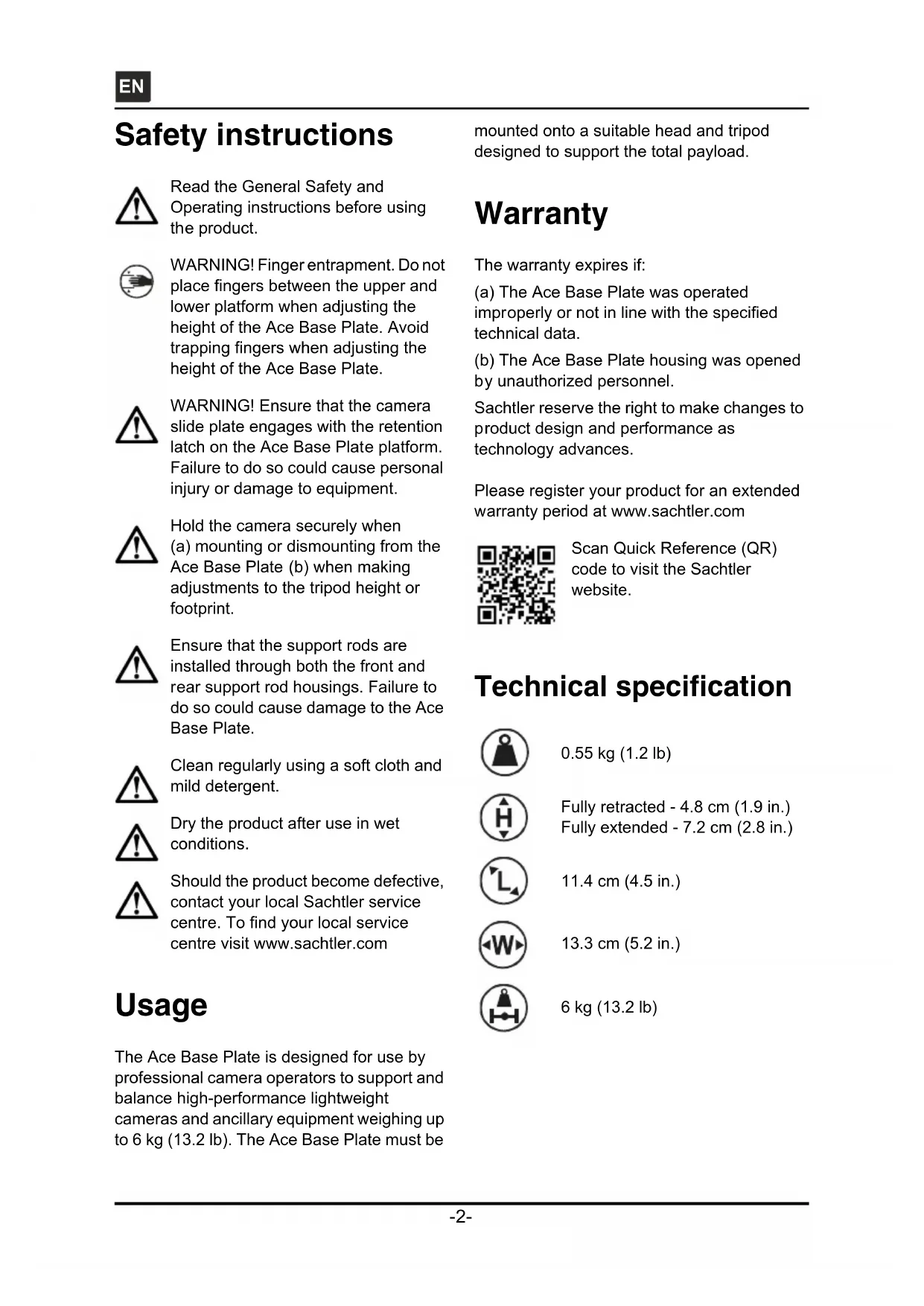
Loosen the slide plate clamping screw. Pull the Ace slide plate to the rear of the fluid head whilst pressing the red release button [B].
Attach the Ace slide plate to the Ace Base Plate using the camera screws and pin supplied. Spare camera screws can be stored under the platform [C].
Lower the Ace Base Plate onto the rear of the head and slide the plate into the track in the platform, ensuring the slide lock release button snaps into position [D].
Steady the Ace Base Plate and tighten the slide plate clamp in a clockwise direction to secure the Ace Base Plate in position [D].


Fig. 2 Mounting the Ace Base Plate
Mounting the camera
The Ace Base Plate is supplied with a camera slide plate, that can be fitted with a 1/4 in. screw and pin assembly. If required, a 3/8 in. screw, located in the spare stowage can be used.
To mount the camera onto the Ace Base Plate (see Fig. 3):
Loosen the slide plate clamping screw. Pull the Ace slide plate to the rear of the Ace Base Plate whilst pressing the red release button [A].
Attach the Ace slide plate to the camera [B].
Ensure that the head platform is level and apply both the pan and tilt brakes.
Lower the camera onto the rear of the Ace Base Plate platform and slide the plate into the track in the platform, ensuring the slide lock release button snaps into position [C].
Steady the camera and rotate the camera slide plate clamp in a clockwise direction to secure the camera in position [C].
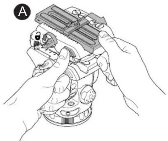
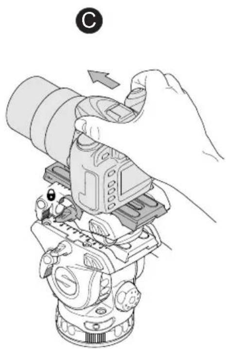

Fig. 3 Mounting the camera
Installing support rods
Two support rods can be fitted to the Ace Base Plate to accommodate an Ace Follow Focus or Ace Matte Box if required.
To fit the support rods to the Ace Base Plate (see Fig. 4):
Insert one end of the rod into the support rod housing at the front left-hand side of the Ace Base Plate, and continue to slide back until it protrudes through the support rod housing at the rear of the Ace Base Plate [A].
Adjust the support rod to the required position and secure with the support rod clamp [B].
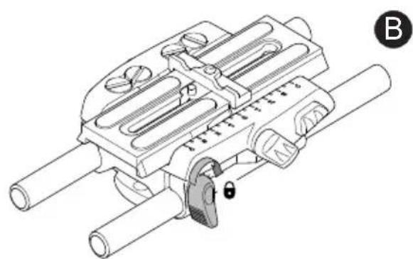
Fig. 4 Support Rod Installation
Ace Base Plate height adjustment
To adjust the Ace Base Plate height (see Fig. 5):

WARNING! Finger entrapment. Do not place fingers between the upper and lower platform when adjusting the height of the Ace Base Plate. Avoid trapping fingers when adjusting the height of the Ace Base Plate.
Rotate the height adjustment knob in a counter-clockwise direction to loosen the platform [A].
Adjust the Ace Base Plate platform to the required height and hold in position [B].
Rotate the height adjustment knob in a clockwise direction to secure the platform [C].


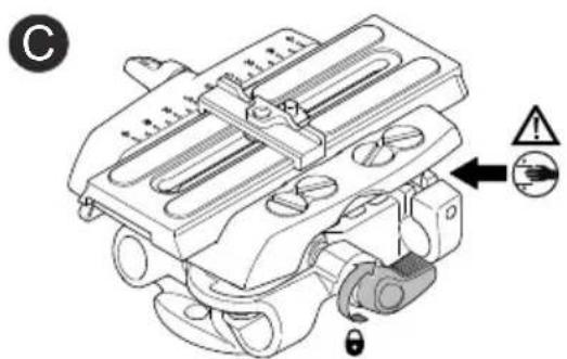
Fig. 5 Ace Base Plate height adjustment
Removing the Ace Base Plate
To remove the Ace Base Plate from the head (see Fig. 2):
Ensure that the head platform is level and apply both the pan and tilt brakes.
Loosen the slide plate clamping screw. Pull the Ace slide plate to the rear of the fluid head whilst pressing the red release button [B].
Whilst holding the camera, slide the Ace Base Plate out to the rear of the platform and away from the head.
Loosen the camera screws on the Ace slide plate, then remove the slide plate from the Ace Base Plate.
Removing the camera.
To remove the camera from the Ace Base Plate (see Fig. 6):
Ensure that the head platform is level and apply both the pan and tilt brakes.
Loosen the slide plate clamping screw. Pull the slide plate to the rear of the fluid head whilst pressing the red release button.
Slide the camera out to the rear of the platform and away from the Ace Base Plate.
Loosen the camera screws securing the Ace slide plate to the camera. Remove the Ace slide plate from the camera.

Fig. 6 Removing the camera
Removing support rods
Ensure Ace Matte Box and Ace Follow Focus are removed from the support rods, if fitted.
To remove the support rods from the Ace Base Plate (see Fig. 4):
Rotate the support rod clamp in a counter-clockwise direction to loosen the support rod [A].
Slide the support rod out of the support rod housing and away from the Ace Base Plate [A].
Maintenance
Cleaning
During indoor use, the only cleaning required should be a regular wipe over with a lint-free cloth. Dirt accumulated during storage may be removed using a semi-stiff brush or vacuum cleaner. Particular attention should be paid to the camera slide plate mounting face, the head slide plate mounting face and the space between the platform and lower assembly.
CAUTION! Do NOT use solvent or oil-based cleaners, abrasives or wire brushes to remove accumulations of dirt, as these damage the protective surfaces. Use only detergent-based cleaners.
Use out-of-doors under adverse conditions will require special attention. Salt spray should be washed off with fresh clean water at the earliest opportunity. Sand and dirt acts as an abrasive and should be removed using a semi-stiff brush or vacuum cleaner.
Inhalt
Seite
- Disclaimer
- Published by:
- Ace Base Plate Manual
- Table of contents
- Page
- Safety instructions 2
- Usage. 2
- Warranty 2
- Technical specification 2
- Operating elements 3
- Operation 5
- Maintenance 10
- Safety instructions
- Usage
- Warranty
- Technical specification
- Operating elements
- Camera slide plate clamping screw
- Slide release button
- Head slide plate attachment
- Support rod adjustment clamp
- Camera height adjustment clamp
- Camera mounting
- Operation
- Mounting the Ace Base Plate
- Mounting the camera
- Installing support rods
- Ace Base Plate height adjustment
- Removing the Ace Base Plate
- Removing the camera.
- Removing support rods
- Maintenance
- Cleaning
- Inhalt
- Seite
Brand : Sachtler
Model : Ace Base Plate
Category : Photo/Video Accessories