11250VSR Professional - Drill BOSCH - Free user manual and instructions
Find the device manual for free 11250VSR Professional BOSCH in PDF.
Download the instructions for your Drill in PDF format for free! Find your manual 11250VSR Professional - BOSCH and take your electronic device back in hand. On this page are published all the documents necessary for the use of your device. 11250VSR Professional by BOSCH.
USER MANUAL 11250VSR Professional BOSCH
11250VSR 11250VSRD 2610047982.qxp_11250VSR,VSRD 10/2/17 1:01 PM Page 1-2- Work area safety Keep work area clean and well lit. Cluttered or dark areas invite accidents. Do not operate power tools in explosive atmospheres, such as in the presence of flammable liquids, gases or dust. Power tools create sparks which may ignite the dust or fumes. Keep children and bystanders away while operating a power tool. Distractions can cause you to lose control. Electrical safety Power tool plugs must match the outlet. Never modify the plug in any way. Do not use any adapter plugs with earthed (grounded) power tools. Unmodified plugs and matching outlets will reduce risk of electric shock. Avoid body contact with earthed or grounded surfaces such as pipes, radiators, ranges and refrigerators. There is an increased risk of electric shock if your body is earthed or grounded. Do not expose power tools to rain or wet conditions. Water entering a power tool will increase the risk of electric shock. Do not abuse the cord. Never use the cord for carrying, pulling or unplugging the power tool. Keep cord away from heat, oil, sharp edges or moving parts. Damaged or entangled cords increase the risk of electric shock. When operating a power tool outdoors, use an extension cord suitable for outdoor use. Use of a cord suitable for outdoor use reduces the risk of electric shock. If operating a power tool in a damp location is unavoidable, use a Ground Fault Circuit Interrupter (GFCI) protected supply. Use of an GFCI reduces the risk of electric shock. Personal safety Stay alert, watch what you are doing and use common sense when operating a power tool. Do not use a power tool while you are tired or under the influence of drugs, alcohol or medication. A moment of inattention while operating power tools may result in serious personal injury. Use personal protective equipment. Always Read all safety warnings and all instructions. Failure to follow the warnings and instructions may result in electric shock, fire and/or serious injury. SAVE ALL WARNINGS AND INSTRUCTIONS FOR FUTURE REFERENCE The term “power tool” in the warnings refers to your mains-operated (corded) power tool or battery-operated (cordless) power tool. General Power Tool Safety Warnings Safety Symbols The definitions below describe the level of severity for each signal word. Please read the manual and pay attention to these symbols.
This is the safety alert symbol. It is used to alert you to potentialpersonal injury hazards. Obey all safety messages that follow thissymbol to avoid possible injury or death.DANGER indicates a hazardous situation which, if not avoided, willresult in death or serious injury.WARNING indicates a hazardous situation which, if not avoided, couldresult in death or serious injury.CAUTION, used with the safety alert symbol, indicates a hazardous situation which, if not avoided, will result in minor or moderate injury. 2610047982.qxp_11250VSR,VSRD 10/2/17 1:01 PM Page 2-3- Rotary Hammer Safety Rules Wear ear protectors. Exposure to noise can cause hearing loss. Use auxiliary handle(s), if supplied with the tool. Loss of control can cause personal injury. Hold power tools by insulated gripping surfaces, when performing an operation where the cutting tool may contact hidden wiring or its own cord. Cutting accessory contacting a "live" wire may make exposed metal parts of the power tool "live" and could give the operator an electric shock. Use clamps or another practical way to secure and support the workpiece to a stable platform. Holding the work by hand or against your body leaves it unstable and may lead to loss of control. Do not drill, fasten or break into existing walls or other blind areas where electrical wiring may exist. If this situation is unavoidable, disconnect all fuses or circuit breakers feeding this worksite. Use a metal detector to determine if there are gas or water pipes hidden in the work area or call the local utility company for assistance before beginning the operation. Striking or cutting into a gas line will result in explosion. Water entering an electrical device may cause electrocution. Always use the side handle for maximum control over torque reaction or kick-back.
ear eye protection. Protective equipment such as dust mask, non-skid safety shoes, hard hat, or hearing protection used for appropriate conditions will reduce personal injuries. Prevent unintentional starting. Ensure the switch is in the off-position before connecting to power source and / or battery pack, picking up or carrying the tool. Carrying power tools with your finger on the switch or energizing power tools that have the switch on invites accidents. Remove any adjusting key or wrench before turning the power tool on. A wrench or a key left attached to a rotating part of the power tool may result in personal injury. Do not overreach. Keep proper footing and balance at all times. This enables better control of the power tool in unexpected situations. Dress properly. Do not wear loose clothing or jewelry. Keep your hair, clothing and gloves away from moving parts. Loose clothes, jewelry or long hair can be caught in moving parts. If devices are provided for the connection of dust extraction and collection facilities, ensure these are connected and properly used. Use of dust collection can reduce dust- related hazards. Power tool use and care Do not force the power tool. Use the correct power tool for your application. The correct power tool will do the job better and safer at the rate for which it was designed. Do not use the power tool if the switch does not turn it on and off. Any power tool that
annot be controlled with the switch is dangerous and must be repaired. Disconnect the plug from the power source and/or the battery pack from the power tool before making any adjustments, changing accessories, or storing power tools. Such preventive safety measures reduce the risk of starting the power tool accidentally. Store idle power tools out of the reach of children and do not allow persons unfamiliar with the power tool or these instructions to operate the power tool. Power tools are dangerous in the hands of untrained users. Maintain power tools. Check for misalignment or binding of moving parts, breakage of parts and any other condition that may affect the power tool’s operation. If damaged, have the power tool repaired before use. Many accidents are caused by poorly maintained power tools. Keep cutting tools sharp and clean. Properly maintained cutting tools with sharp cutting edges are less likely to bind and are easier to control. Use the power tool, accessories and tool bits etc. in accordance with these instructions, taking into account the working conditions and the work to be performed. Use of the power tool for operations different from those intended could result in a hazardous situation. Service Have your power tool serviced by a qualified repair person using only identical replacement parts. This will ensure that the safety of the power tool is maintained. 2610047982.qxp_11250VSR,VSRD 10/2/17 1:01 PM Page 3N ever attempt to operate this tool with one hand. The slip clutch engages if you firmly control the tool during a torque reaction or kickback. Always wear safety goggles or eye protection when using this tool. Use a dust mask or respirator for applications that generate dust. Safety goggles or eye protection will help deflect fragments of the material that may be thrown toward your face and eyes. Dust generated or gases released from the material you are cutting (i.e. asbestos insulated pipes, radon) may cause respiratory difficulties. Use thick cushioned gloves and limit the exposure time by taking frequent rest periods. Vibration caused by hammer-drill action may be harmful to your hands and arms. Position the cord clear of rotating bit. Do not wrap the cord around your arm or wrist. If cord becomes entangled with the spinning bit it could entrap you causing serious personal injury.
osition yourself to avoid being caught between the tool or side handle and walls or posts. Should the bit become bound or jammed in the work, the reaction torque of the tool could crush your hand or leg. Do not strike the bit with a handheld hammer or sledgehammer when attempting to dislodge a bound or jammed bit. Fragments of metal from the bit could dislodge and strike you or bystanders. Never place the tool down until the bit or accessory has come to a complete stop. Do not use dull or damaged bits and accessories. Dull or damaged bits have a greater tendency to bind in the workpiece. When removing the bit from the tool avoid contact with skin and use proper protective gloves when grasping the bit or accessory. Accessories may be hot after prolonged use. Do not run the tool while carrying it at your side. A spinning bit could become entangled with clothing and injury may result.
Additional Safety Warnings GFCI and personal protection devices like electrician’s rubber gloves and footwear will further enhance your personal safety. Do not use AC only rated tools with a DC power supply. While the tool may appear to work, the electrical components of the AC rated tool are likely to fail and create a hazard to the operator. Keep handles dry, clean and free from oil and grease. Slippery hands cannot safely control the power tool. Develop a periodic maintenance schedule for your tool. When cleaning a tool be careful not to disassemble any portion of the tool since internal wires may be misplaced or pinched or safety guard return springs may be improperly mounted. Certain cleaning agents such as gasoline, carbon tetrachloride, ammonia, etc. may damage plastic parts. Risk of injury to user. The power cord must only be serviced by a Bosch Factory Service Center or Autho rized Bosch Service Station. Some dust created by power sanding, sawing, grinding, drilling, and other construction activities contains chemicals known to cause cancer, birth defects or other reproductive harm. Some examples of these chemicals are:
- Lead from lead-based paints,
- Crystalline silica from bricks and cement and other masonry products, and
- Arsenic and chromium from chemically- treated lumber. Your risk from these exposures varies, depending on how often you do this type of work. To reduce your exposure to these chemicals: work in a well ventilated area, and work with approved safety equipment, such as those dust masks that are specially designed to filter out microscopic particles. 2610047982.qxp_11250VSR,VSRD 10/2/17 1:01 PM Page 4-5- Symbols IMPORTANT: Some of the following symbols may be used on your tool. Please study them and learn their meaning. Proper interpretation of these symbols will allow you to operate the tool better and safer. Symbol Designation / Explanation V Volts (voltage) A Amperes (current) Hz Hertz (frequency, cycles per second) W Watt (power) kg Kilograms (weight) min Minutes (time) s Seconds (time)
Diameter (size of drill bits, grinding wheels, etc.)
No load speed (rotational speed at no load) n Rated speed (maximum attainable speed) .../min Revolutions or reciprocation per minute (revolutions, strokes, surface speed, orbits etc. per minute) 0 Off position (zero speed, zero torque...) 1, 2, 3, ... I, II, III, Selector settings (speed, torque or position settings. Higher number means greater speed)
Infinitely variable selector with off (speed is increasing from 0 setting) Arrow (action in the direction of arrow) Alternating current (type or a characteristic of current) Direct current (type or a characteristic of current) Alternating or direct current (type or a characteristic of current) Class II construction (designates double insulated construction tools) Earthing terminal (grounding terminal) 2610047982.qxp_11250VSR,VSRD 10/2/17 1:01 PM Page 5-6- Symbols (continued) Conforms to UL Standard 60745-1 UL Standard 60745-2-6 Certified to CAN/CSA Standard C22.2 No. 60745-1-07 CAN/CSA Standard C22.2 No. 60745-2-6-04 IMPORTANT: Some of the following symbols may be used on your tool. Please study them and learn their meaning. Proper interpretation of these symbols will allow you to operate the tool better and safer. Symbol Designation / Explanation Alerts user to read manual Alerts user to wear eye protection This symbol designates that this tool is listed by Underwriters Laboratories. This symbol designates that this tool is listed by Underwriters Laboratories, to United States and Canadian Standards. This symbol designates that this tool is listed by the Canadian Standards Association. This symbol designates that this tool is listed by the Canadian Standards Association, to United States and Canadian Standards. This symbol designates that this tool is listed by the Intertek Testing Services, to United States and Canadian Standards. This symbol designates that this tool complies to NOM Mexican Standards. 2610047982.qxp_11250VSR,VSRD 10/2/17 1:01 PM Page 6-7- Functional Description and Specifications Disconnect the plug from the power source before making any assembly, adjustments or changing accessories. Such preventive safety measures reduce the risk of starting the tool accidentally. 11250VSR Rotary Hammer Model number 11250VSR Shank style SDS-Plus
Maximum Capacities: Concrete 3/4" *Steel 1/2" *Wood 3/4" Carbide tipped bits 3/4" Thin wall core bits 1-1/2"
- 3-Jaw Chuck adaptor required NOTE: For tool specifications refer to the nameplate on your tool.
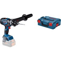
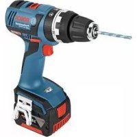
SELECTION DIAL VARIABLE SPEED CONTROLLED TRIGGER SWITCH OFFSET AUXILIARY HANDLE FIG. 1 2610047982.qxp_11250VSR,VSRD 10/2/17 1:01 PM Page 7-8- Functional Description and Specifications Disconnect the plug from the power source before making any assembly, adjustments or changing accessories. Such preventive safety measures reduce the risk of starting the tool accidentally. 11250VSRD Rotary Hammer Model number 11250VSRD Shank style SDS-Plus
Maximum Capacities: Concrete 3/4" Carbide tipped bits 3/4" Thin wall core bits 1-1/2" NOTE: For tool specifications refer to the nameplate on your tool. BoschhammerBoschhammerBoschhammerBoschhammerBoschhammer
ACCESSORIESClean the insert shank end of the accessory toremove any debris, then lightly grease with alight oil or lubricantInsert accessory into the chuck through thedust shield, while twisting and pushing inwarduntil it locks automatically into place. Pulloutward on the accessory to be certain it islocked into the chuck (Fig. 3).NOTE: The high efficiency available from therotary hammers can only be obtained if sharpand undamaged accessories are used. The"cost" to maintain sharp and undamagedaccessories is more than offset by the "timesaved" in operating the tool with sharpaccessories.REMOVING SDS-plus ACCESSORIESAccessories may be hotafter use. Avoid contactwith skin and use proper protective gloves orcloth to remove.To remove an accessory, pull locking sleevebackward and pull bit forward. All accessoriesshould be wiped clean after removing (Fig. 4).
FIG. 3 FIG. 4 DUST SHIELDLOCKINGSLEEVESDS-plus CHUCKINSTALLING & REMOVING 3-JAW CHUCK(Not included, available as accessory)The 3 Jaw Chuck with SDS Shank can convertyour tool for use with straight shank bits.Clean the insert shank end of the accessory toremove any debris, then lightly grease with alight oil or lubricantInsert accessory into the chuck through thedust shield, while twisting and pushing inwarduntil it locks automatically into place. Pulloutward on the accessory to be certain it islocked into the chuck (Fig. 5).To remove the chuck, pull the locking sleevebackward (towards the rear of tool), whilepulling the chuck forward.
The tool must be supported with the auxiliary handle, which can be swiveled 360˚. To reposition and/or swivel the handle, loosen the hand grip, move the handle to the desired position along the barrel and securely retighten the hand grip (Fig. 7).
NSTALLING & REMOVING ACCESSORIES
3-JAW CHUCK For small bits, open jaws enough to insert the bit up to the flutes. For large bits, insert the bit as far as it will go. Center the bit as you close the jaws by hand. This positions the bit properly, giving maximum contact between the chuck jaws and the bit shank (Fig. 6). To tighten chuck, insert key into each of the three key holes in succession and tighten clockwise firmly. The chuck can be released by using one hole only. Note: The 3-Jaw Chuck is for use only in “Drill only” mode. The 3-Jaw Chuck is not for use when drilling with hammering action.
TRIGGER SWITCH Your tool is equipped with a variable speed trigger switch. The tool speed can be controlled from the minimum to the maximum nameplate RPM by the pressure you apply to the trigger. Apply more pressure to increase the speed and release pressure to decrease speed. This accurate speed control enables you to drill without center punching. It also permits you to use as a power screwdriver. Bits are available for driving screws as well as running bolts and nuts (Fig. 8). Operating Instructions REVERSING SWITCH LEVER VARIABLE SPEED CONTROLLED TRIGGER SWITCH FIG. 8 2610047982.qxp_11250VSR,VSRD 10/2/17 1:01 PM Page 10-11-
This tool is equipped with a rotating brush reversing system. This results in longer tool life while maximizing power in both forward and re - verse directions. The reverse switch can be oper ated from either the right or left side of the tool. FOR FORWARD ROTATION: slide switch to arrow marked forward (Fig. 9). FOR REVERSE RO TATION: slide the slide switch to arrow marked re verse. NOTE: Tool will not operate in middle position. SLIP CLUTCH The tool has an internal preset clutch. The clutch is set such that sufficient force is transmitted to the bit for most drilling conditions but it will slip when bit binds in the hole or the tool is overloaded. Be aware that due to required clutch setting, you may
xperience a torque reaction an instant before the clutch slips. This torque reaction will twist the body of the rotary hammer in the opposite direction as the bit rotates, i.e., counterclockwise. As clutch is slipping, the bit will most likely stop rotating. When the binding force on the bit is removed the clutch automatically resets. If you experience bit binding and clutch begins to slip, immediately turn the tool "OFF" and correct the condition leading to the bit binding.
DRILL/HAMMER DRILL SELECTION DIAL
The selector dial allows the tool to be set for various drilling/hammer drilling applications . Depress release button and turn selector dial right or left depending on the below applications. Do not operate the selection dial until the tool come to a complete stop. Shifting during rotation of the chuck can cause damage to the tool. Do not use demolition or chipping bits such as bull points, chisels, spades, gouges, etc. Drill only action: For drilling in woods, metals, plastics or other non concrete materials. Drill with hammer action: For drilling in concrete, asphalt, tile or other similar hard materials.
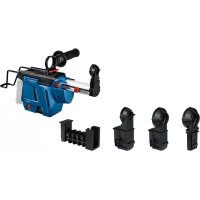
REMOVING AND INSTALLING DUST
EXTRACTION SYSTEM To remove dust extraction system, press and hold the dust extraction release button and pull away from tool housing (Fig. 10). To install dust extraction system, align guide grooves with the grooves in tool housing and push toward tool until you hear it lock into place (Fig. 10). BoschhammerBoschhammerBoschhammerBoschhammerBoschhammerBoschhammerBoschhammerBoschhammerBoschhammerBosch
Your tool is equipped with a standard dust cap for use with with small drill bits. To change the dust cap, push the release button and pull the dust cap out of the dust extraction system. To insert the dust cap, push it into the end of the dust extraction system until you hear it lock into place (Fig. 11).
(Not included, available as accessory) When using core bits, the dust cap for small drill bits must be removed and replaced with a special dust cap for core bits (optional accessory).
hen using the dust cap for core bits (optional accessory), the vacuum adapter dust canister (optional accessory) must be used for dust extraction, not the standard dust canister (Fig. 12). If required, remove the dust cap for small drill bits. To insert the dust cap for core bits, push it from above into the dust extraction system until you hear it click into place (Fig. 12). To remove of the dust cap for core bits, push the release latch outward and pull off the dust cap. The dust extraction system retracts during operation so that the dust cap is always kept close to surface being drilled. The dust extraction system automatically switches on and off with the power tool. For maximum dust extraction efficiency, please observe the following.
- The drill bit being used may not project beyond the dust cap as shown in figures 11 &
12. (Example for an SDS-plus drill bit: Max.
total length approx. 160 mm, working length approx. 100 mm).
- Pay attention that the dust cap faces flush against the workpiece or the wall. At the same time, this makes working at a right angle easier.
- After reaching desired drilling depth, first pull the drill bit out of the hole and then switch the tool off.
- Check the condition of the microfilter regularly. Replace a damaged microfilter immediately. DEPTH GAUGE Your drilling depth X can be pre-set and/or repeated by using the depth gauge (Fig. 13). After the auxiliary handle is installed, make sure the accessory has been fully inserted into the chuck before setting the depth gauge. Set the depth gauge by compressing the telescopic guide toward the tool. When the desired length of the bit is exposed, press and slide the depth stop button against the guide housing and release the button (Fig. 13). The depth gauge is spring loaded and will return to the fully extended position when pressure has been released. (When drilling, the telescopic guide will compress until it engages the depth stop button.) DUST CAP RELEASE BUTTON DUST CAP
For more convenient operation when using short drill bits, the length of the telescopic guide can be adjusted to desired lengths. To adjust length, push and hold the guide adjustment button, compress the telescopic guide until dust cap is close to the tip of the drill bit (Fig. 14). To lock adjustment, release button. To unlock adjustment, push the guide adjustment button.
MICROFILTER DUST CANISTER
The integral dust extraction system collects dust in a canister supplied with your extraction system. The dust level of the dust canister can easily be checked through the transparent door (Fig. 15). For maximum efficiency, the dust canister should be emptied frequently during operation.
REMOVING DUST CANISTER
To remove dust canister, press the two canister release buttons and pull canister downward out of the dust extraction system (Fig. 15).
CLEANING AND EMPTYING THE
DUST CANISTER Before opening the dust canister, gently strike or tap it against a firm surface to loosen the dust from the microfilter. Open the transparent door and empty the dust canister. Close transparent door. Check the microfilter for damage. Replace it immediately when damaged.
INSTALLING DUST CANISTER
To install dust canister, push canister upward into the dust extraction system until you hear it lock into place (Fig. 15).
CHANGING THE MICROFILTER
For maximum efficiency, the microfilter should be replaced after approx. 15 hours of operation. Remove the dust canister from the dust extraction system (Fig. 15). Lift the microfilter upward and remove old or damaged filter from dust canister (Fig. 16). Insert a new microfilter into the dust canister and reinstall the dust canister (Fig. 16.) Note: If the microfilter is damaged (e.g. holes, damage to the soft sealing material), it must be replaced immediately. Working with a damaged microfilter can cause damage to the power tool.
TELESCOPIC GUIDE DEPTH STOP BUTTON GUIDE HOUSING FIG. 13 FIG. 14 GUIDE ADJUSTMENT BUTTON DUST SEAL DUST CAP 2610047982.qxp_11250VSR,VSRD 10/2/17 1:01 PM Page 13Tool Tips Following a few simple tips will reduce wear on the tool and the chance of injury to the operator. NOTE: The high efficiency available from the rotary hammers can only be obtained if sharp and undamaged accessories are used. The “cost” to maintain sharp and undamaged accessories is more than offset by the “time saved” in operating the tool with sharp accessories. All hammers require a short period of time to warm up. Depending on the room temperature, this time may vary from approximately 15 seconds (90˚F) to 2 minutes (32˚F). A new hammer requires a break-in period before full performance is realized. This period may require up to 5 hours of operation. Carbide tipped bits: Used for drilling stone, concrete, cement, brick, cinder block and other unusually hard non-metals. The Rotary Hammer is designed for “SDS” Carbide Tipped Bits up to 3/4 inch diameter. Recall these instructions for safe operation:
1. Some materials require slow drilling
speeds; whereas, others require higher speed to produce the best results.
2. All work must be supported or secured
before drilling and steady, even pressure applied in line with the drill bit.
3. As the drill bit cuts through the opposite
side, reduce the pressure and continue running the drill as the bit is withdrawn. Materials such as glass, porcelain, ceramics, tiles, plastics, etc., should be drilled at low speeds with specially designed drill bits and lubricants.
lso replace the microfilter when the vacuuming performance is insufficient, even when the dust canister is empty.
VACUUM ADAPTER DUST CANISTER
(Not included, available as accessory) For dust extraction with a vacuum cleaner, the (optional) vacuum adapter dust canister can be inserted into the dust extraction system instead of the dust canister, if required. Press the two canister release buttons and pull canister downward and remove from the dust extraction system (Fig. 15).
nstall vacuum adapter dust canister upward into dust extraction system until you hear it lock into place (Fig. 17). To use this feature, attach vacuum hose (optional accessory) to dust port, then connect opposite end of the vacuum hose to a shop vacuum cleaner. A vacuum hose adapter (optional accessory) is available for connecting this tool to a 1-1/4" or 1-1/2" vacuum hose (Fig. 17). The vacuum cleaner must be suitable for the material being drilled.
Do not drill into wood with dust extraction system mounted. Wood chips are typically too large and will clog the dust channel. If backing block is not used, ease up on the pressure just before the bit breaks through the wood to avoid splintering. Complete the hole from the opposite side immediately after the point breaks through. If bit binds, reverse the drilling operation to help remove the bit from the work. DRILLING METAL Do not drill into metal with the dust extraction system mounted. Hot metal chips can self- ignite or ignite parts of the dust extraction system. Make a center punch in the material for
asier starting. Use enough pressure to keep the bit cutting. If the bit is allowed to merely spin in the hole, it will become dull within a short time. When drilling a larger hole, it is faster and easier on your power pack to first make a smaller hole and enlarge it to the required size. Lubricate the tip of the bit occasionally with CUTTING OIL for easier metal drilling. If bit binds, reverse the drilling to help remove the bit from the work. DRILLING MASONRY Use carbide-tipped masonry bit for cinder block, mortar, common brick, soft stone and other materials. The amount of pressure to be used is dependent upon the type of material being drilled. Soft materials require less pressure while the hard materials need more pressure to prevent the drill bit from skipping.
Dust Extraction (Model 11250VSR only) For selection of dust collection systems and operating instructions, see the Operating / Safety Instructions for ‘Dust Extraction Attachments for Hammers and Hammer Drills’ included with your tool or with the dust extraction attachment. 2610047982.qxp_11250VSR,VSRD 10/2/17 1:01 PM Page 15-16- Service Preventive maintenance performed by unauth- orized per so n nel may result in misplacing of internal wires and components which could cause serious hazard. We recommend that all tool service be performed by a Bosch Factory Service Center or Autho - rized Bosch Service Station. TOOL LUBRICATION Your Bosch tool has been properly lubricated and is ready to use. It is recommended that tools with gears be regreased with a special gear lubricant at every brush change. CARBON BRUSHES The brushes and commutator in your tool have been engineered for many hours of dependable service. To maintain peak efficiency of the motor, we recommend every two to six months the brush es be examined. Only genuine Bosch replace ment brushes specially designed for your tool should be used. BEARINGS
earings which become noisy (due to heavy load or very abrasive material cut ting) should be replaced at once to avoid overheating or motor failure. Cleaning To avoid accidents always dis connect the tool from the power supply before cleaning or performing any main tenance. The tool may be cleaned most effectively with compressed dry air. Always wear safety gog gles when cleaning tools with compressed air. Ventilation openings and switch levers must be kept clean and free of foreign matter. Do not at tempt to clean by inserting pointed objects through openings. Certain cleaning agents and sol vents damage plastic parts. Some of these are: gasoline, carbon tetrachlo ride, chlo rinated cleaning solvents, ammonia and house hold detergents that contain ammonia. Maintenance
- 360° Auxiliary Handle ** Dust extraction system ** Dust cap ** Dust seal ** Dust cap (for hole saws) ** Vacuum adapter dust canister ** Vacuum hose Adapter ** Vacuum hose ** 3-Jaw Chuck adaptor
- Carrying Case (*= standard equipment) (**= optional accessories) Accessories If an extension cord is necessary, a cord with adequate size conductors that is capable of carrying the current necessary for your tool must be used. This will prevent excessive voltage drop, loss of power or overheating. Grounded tools must use 3-wire extension cords that have 3-prong plugs and receptacles. NOTE: The smaller the gauge number, the higher the cord capacity. RECOMMENDED SIZES OF EXTENSION CORDS120 VOLT ALTERNATING CURRENT TOOLSTool’s Ampere RatingCord Size in A.W.G. Wire Sizes in mm Cord Length in Feet Cord Length in Meters25 50 100 15015 30 60 120 3-6 6-8 8-10 10-1212-16
obert Bosch Tool Corporation (“Seller”) warrants to the original purchaser only, that all BOSCH portable and benchtop power tools will be free from defects in material or workmanship for a period of one year from date of purchase. SELLER’S SOLE OBLIGATION AND YOUR EXCLUSIVE REMEDY under this Limited Warranty and, to the extent permitted by law, any warranty or condition implied by law, shall be the repair or replacement of parts, without charge, which are
efective in material or workmanship and which have not been misused, carelessly handled, or misrepaired by persons other than Seller or Authorized Service Station. To make a claim under this Limited Warranty, you must return the complete portable or benchtop power tool product, transportation prepaid, to any BOSCH Factory Service Center or Authorized Service Station. For Authorized BOSCH Power Tool Service Stations, please refer to your phone directory. THIS LIMITED WARRANTY DOES NOT APPLY TO ACCESSORY ITEMS SUCH AS CIRCULAR SAW BLADES, DRILL BITS, ROUTER BITS, JIGSAW BLADES, SANDING BELTS, GRINDING WHEELS AND OTHER RELATED ITEMS. ANY IMPLIED WARRANTIES SHALL BE LIMITED IN DURATION TO ONE YEAR FROM DATE OF PURCHASE. SOME STATES IN THE U.S., SOME CANADIAN PRO V -