USER MANUAL PFS 800 A1 PARKSIDE
natural_image
Technical line drawing of a mechanical assembly with labeled components (no readable text or symbols)

WET TILE CUTTER PFS 800 A1

Wet Tile Cutter
Operating and Safety Instructions
Translation of the original operating instructions
WARNING: READ CAREFULLY BEFORE USE AND STORE IN A SAFE PLACE FOR FUTURE REFERENCE.

Tegelsnijmachine
WAARSCHUWING: VOOR GEBRUIK ZORGVULDIG
DOORLEZEN EN GOED BEWAREN VOOR LATER GEBRUIK.

Before reading, unfold the page with the illustrations and then familiarise yourself with all the functions of the product.

GB / IE / NI Operating and Safety Instructions Page 1
natural_image
Technical line drawing of a mechanical assembly with no visible text or symbols
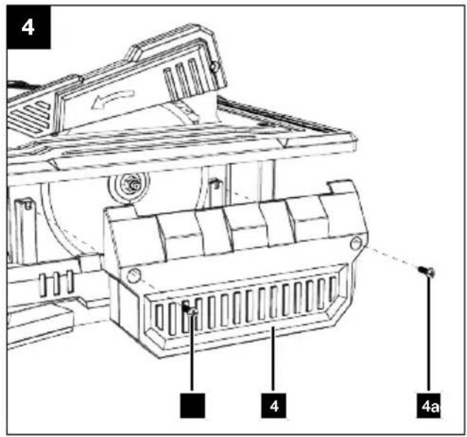
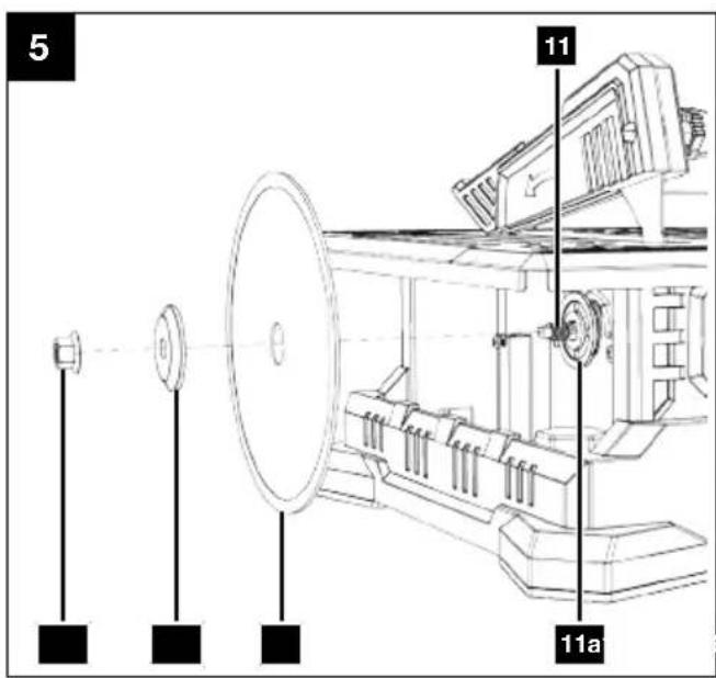
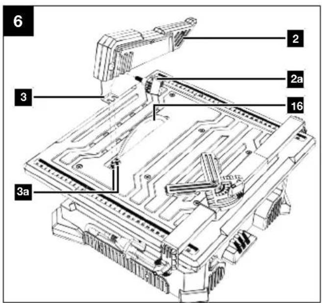
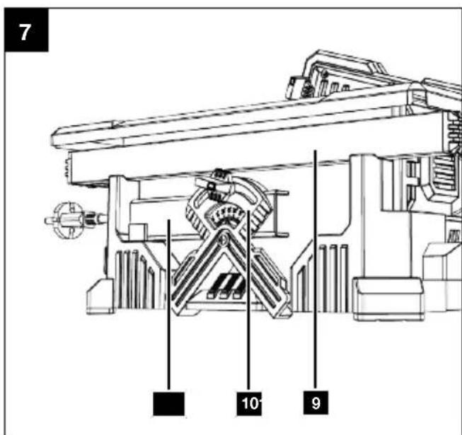
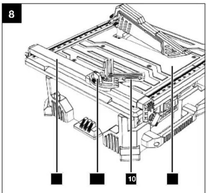
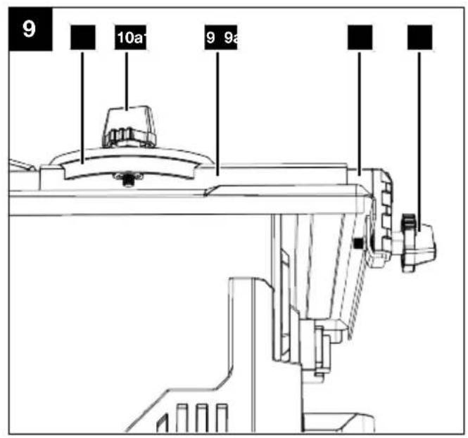
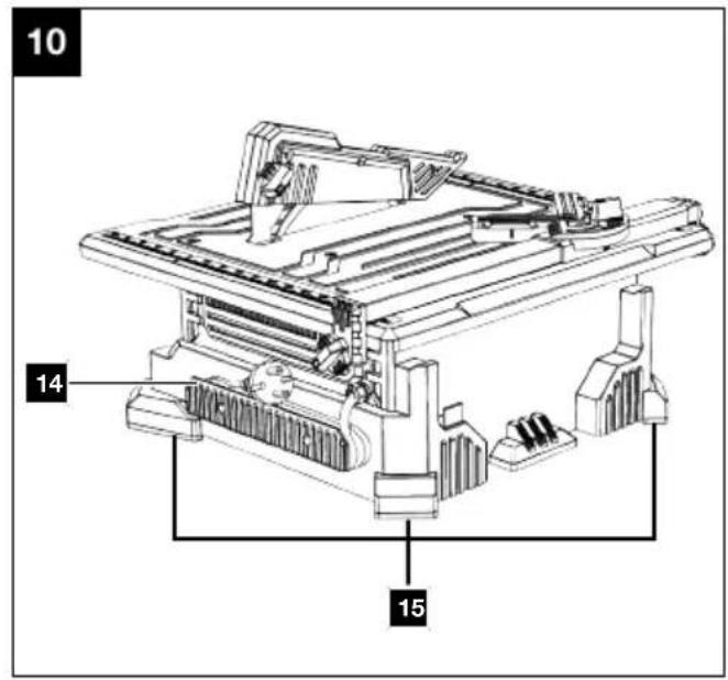
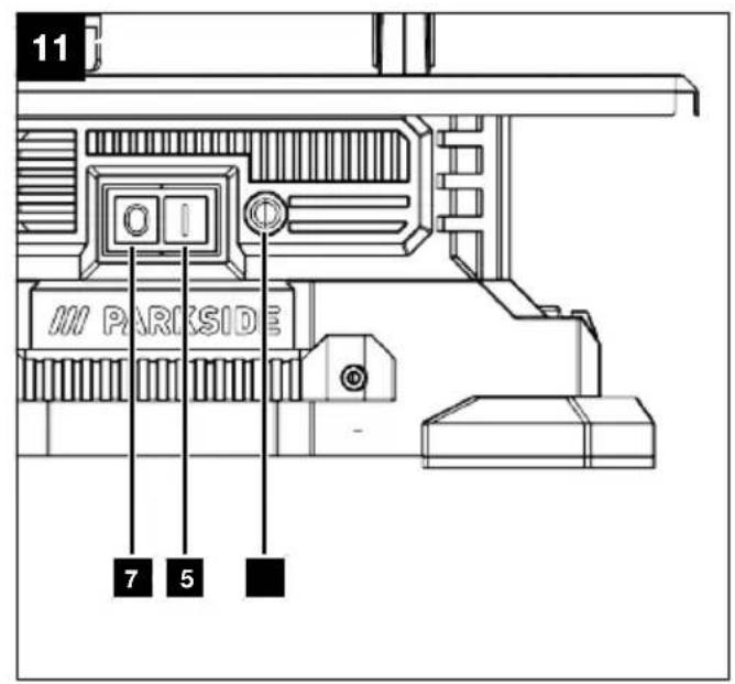
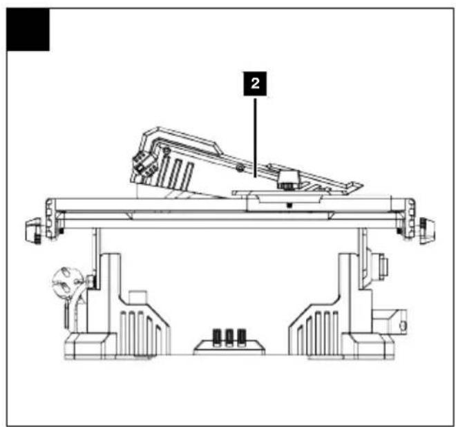
Table of contents
1 Explanation of the symbols on the product.... 2
2 Introduction.... 3
3 Product description (Fig. 1-12) 3
4 Scope of delivery (Fig. 2).... 3
5 Proper use.... 3
6 Safety instructions 4
7 Technical data.... 7
8 Unpacking.... 7
9 Assembly.... 8
10 Before commissioning 9
11 Operation 9
12 Working instructions (Fig. 1) 10
13 Cleaning and maintenance 11
14 Transport.... 12
15 Storage.... 12
16 Electrical connection.... 13
17 Repair and ordering spare parts 13
18 Disposal and recycling.... 14
19 Troubleshooting.... 14
20 Maintenance plan.... 15
21 EU Declaration of Conformity 15
22 Warranty certificate.... 16
23 Exploded view.... 87
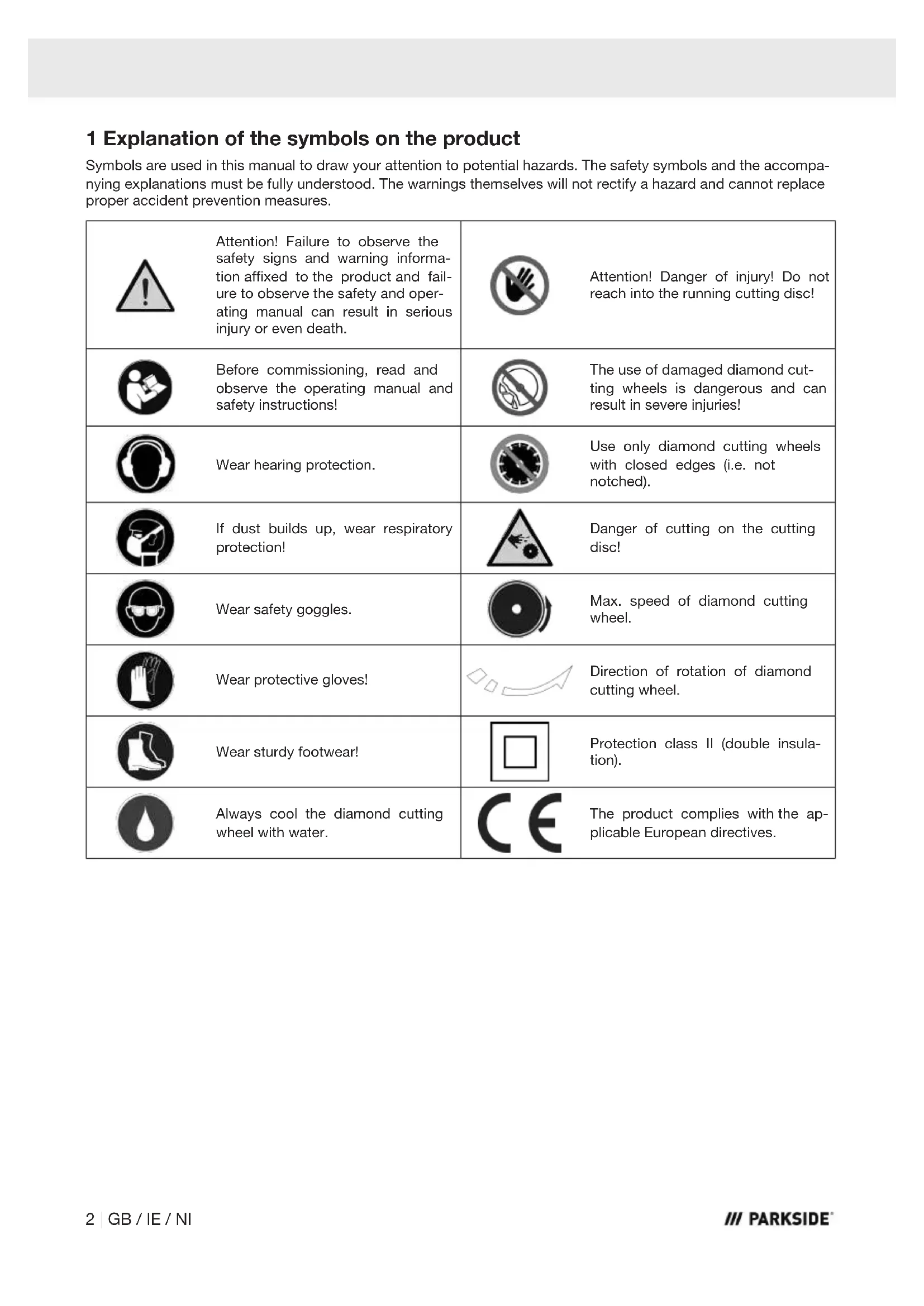
1 Explanation of the symbols on the product
Symbols are used in this manual to draw your attention to potential hazards. The safety symbols and the accompanying explanations must be fully understood. The warnings themselves will not rectify a hazard and cannot replace proper accident prevention measures.
 | Attention! Failure to observe the safety signs and warning information affixed to the product and failure to observe the safety and operating manual can result in serious injury or even death. |  | Attention! Danger of injury! Do not reach into the running cutting disc! |
 | Before commissioning, read and observe the operating manual and safety instructions! |  | The use of damaged diamond cutting wheels is dangerous and can result in severe injuries! |
 | Wear hearing protection. |  | Use only diamond cutting wheels with closed edges (i.e. not notched). |
 | If dust builds up, wear respiratory protection! | 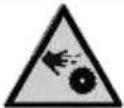 | Danger of cutting on the cutting disc! |
 | Wear safety goggles. |  | Max. speed of diamond cutting wheel. |
 | Wear protective gloves! |  | Direction of rotation of diamond cutting wheel. |
 | Wear sturdy footwear! |  | Protection class II (double insulation). |
 | Always cool the diamond cutting wheel with water. |  | The product complies with the applicable European directives. |
2 Introduction
Manufacturer:
Scheppach GmbH
Günzburger Straße 69
D-89335 Ichenhausen
Dear Customer
We hope your new product brings you much enjoyment and success.
Note:
In accordance with the applicable product liability laws, the manufacturer of this product assumes no liability for damage to the product or caused by the product arising from:
- Improper handling
- Failure to comply with the operating manual
- Repairs carried out by third parties, unauthorised specialists
• Installing and replacing non-original spare parts
- Improper use
- Failures of the electrical system in the event of the electrical regulations and VDE provisions 0100, DIN 57113 / VDE0113 not being observed.
Note:
The operating manual is part of this product.
It includes important instructions for the safe, proper and economic operation of the product, for avoiding danger, for minimising repair costs and downtimes and for increasing the reliability and extending the service life of the product. In addition to the safety instructions in this operating manual, you must also observe the regulations applicable to the operation of the product in your country.
Familiarise yourself with all operating and safety instructions before using the product. Only operate the product as described and for the specified areas of application. Keep the operating manual in a good place and hand over all documents when passing the product on to third parties.
3 Product description (Fig. 1-12)
- Table
- Protective cover
2a. Screw
- Riving knife
3a. Screws
- Cover
4a. Screw
- Overload switch
- On switch
- Off switch
- Handle
- Parallel stop
9a. Clamping screw
9b. Screw
9c. Metal clamp
9d. Cover
10. Angular stop
10a. Locking screw
10b. Guide rail
11. Motor shaft
11a. Internal flange
11b. External flange
11c. Fixing nut
12. Plug
13. Level indicator
14. Cable holder
15. Foot
16. Diamond cutting wheel
17. Open-ended spanner, 6/8 mm
18. Open-ended spanner, 13/15 mm
4 Scope of delivery (Fig. 2)
Item Quantity Designation
-
1 x Protective cover
-
1 x Riving knife
-
1 x Parallel stop
9a. 2 x Clamping screw
9b. 2 x Screw
9c. 2 x Metal clamp
9d. 2 x Cover
- 1 x Angular stop
10a. 1 x Locking screw
10b. 1 x Guide rail
-
1 x Diamond cutting wheel
-
1 x Open-ended spanner, 6/8 mm
-
1 x Open-ended spanner, 13/15 mm
1 x Tile cutter
1 x Operating manual
5 Proper use
The tile cutter can be used for common cutting work on small and medium-sized tiles (tiles, ceramics or similar) according to the machine size. Cutting metal and wood is not permitted.
The product may only be used in the intended manner. Any use beyond this is improper. The user, not the manufacturer, is responsible for damages or injuries of any type resulting from this.
An element of the intended use is also the observance of the safety instructions, as well as the assembly instructions and operating information in the operating manual.
Persons who operate and maintain the product must be familiar with the manual and must be informed about potential dangers.
The liability of the manufacturer and resulting damages are excluded in the event of modifications of the product.
The product may only be operated with original parts and original accessories from the manufacturer.
The safety, operating and maintenance specifications of the manufacturer, as well as the dimensions specified in the technical data, must be observed.
Please note that our products were not designed with the intention of use for commercial or industrial purposes. We assume no guarantee if the product is used in commercial or industrial applications, or for equivalent work.
Any other use not expressly permitted in these instructions may result in damage to the product and pose a serious danger to the user.
The product is intended for use by adults. Children under the age of 16 may only use the product when supervised. The manufacturer is not liable for damage caused by improper use or incorrect operation.
Explanation of the signal words in the operating manual

DANGER
Signal word to indicate an imminently hazardous situation which, if not avoided, will result in death or serious injury.

WARNING
Signal word to indicate a potentially hazardous situation which, if not avoided, could result in death or serious injury.

CAUTION
Signal word to indicate a potentially hazardous situation which, if not avoided, could result in minor or moderate injury.
ATTENTION
Signal word to indicate a potentially hazardous situation which, if not avoided, could result in product or property damage.
6 Safety instructions
General power tool safety warnings

WARNING
Read all safety warnings, instructions, illustrations and specifications provided with this power tool.
Failure to follow all instructions listed below may result in electric shock, fire and/or serious injury.
Save all warnings and instructions for future reference.
The term “power tool” in the warnings refers to your mains-operated (corded) power tool or battery-operated (cordless) power tool.
1) Work area safety
a) Keep your work area clean and well-lit. Cluttered or dark areas invite accidents.
b) Do not operate power tools in explosive atmospheres, such as in the presence of flammable liquids, gases or dust. Power tools create sparks which may ignite the dust or fumes.
c) Keep children and bystanders away while operating a power tool. Distractions can cause you to lose control.
2) Electrical safety
a) The connection plug of the electric tool must fit into the socket. Never modify the plug in any way. Do not use any adapter plugs with earthed (grounded) power tools. Unmodified plugs and matching outlets will reduce risk of electric shock.
b) Avoid body contact with earthed or grounded surfaces, such as pipes, radiators, ranges and refrigerators. There is an increased risk of electric shock if your body is earthed or grounded.
c) Do not expose power tools to rain or wet conditions. Water entering a power tool will increase the risk of electric shock.
d) Do not abuse the cord. Never use the cord for carrying, pulling or unplugging the power tool. Keep cord away from heat, oil, sharp edges or moving parts. Damaged or entangled cords increase the risk of electric shock.
e) When operating a power tool outdoors, use an extension cord suitable for outdoor use. Use of a cord suitable for outdoor use reduces the risk of electric shock.
f) If operating a power tool in a damp location is unavoidable, use a residual current device (RCD) protected supply. Use of an RCD reduces the risk of electric shock.
3) Personal safety
a) Stay alert, watch what you are doing and use common sense when operating a power tool. Do not use a power tool while you are tired or under the influence of drugs, alcohol or medication. A moment of inattention while operating power tools may result in serious personal injury.
b) Wear personal protective equipment and always safety goggles. Protective equipment such as a dust mask, non-skid safety shoes, safety helmet or hearing protection used for appropriate conditions will reduce personal injuries.
c) Prevent unintentional starting. Ensure the switch is in the off-position before connecting to power source and/or rechargeable battery, picking up or carrying the tool. Carrying power tools with your finger on the switch or energising power tools that have the switch on invites accidents.
d) Remove any adjusting tools or spanners/keys before turning the power tool on. A wrench or a key left attached to a rotating part of the power tool may result in personal injury.
e) Avoid abnormal postures. Keep proper footing and balance at all times. This enables better control of the power tool in unexpected situations.
f) Dress properly. Do not wear loose clothing or jewellery. Keep your hair and clothing away from moving parts. Loose clothes, jewellery or long hair can be caught in moving parts.
g) If devices are provided for the connection of dust extraction and collection facilities, ensure these are connected and properly used. Use of dust extraction can reduce dust-related hazards.
h) Do not let familiarity gained from frequent use of tools allow you to become complacent and ignore tool safety principles. A careless action can cause severe injury within a fraction of a second.
a) Do not force the power tool. Use the correct power tool for your application. The correct power tool will do the job better and safer at the rate for which it was designed.
b) Do not use the power tool if the switch does not turn it on and off. Any power tool that cannot be controlled with the switch is dangerous and must be repaired.
c) Disconnect the plug from the power source and/or remove the battery pack, if detachable, from the power tool before making any adjustments, changing accessories, or storing power tools. Such precautionary measures reduce the risk of starting the power tool accidentally.
d) Store idle power tools out of the reach of children and do not allow persons unfamiliar with the power tool or these instructions to operate the power tool. Power tools are dangerous in the hands of untrained users.
e) Maintain power tools and attachments. Check for misalignment or binding of moving parts, breakage of parts and any other condition that may affect the power tool's operation. If damaged, have the power tool repaired before use. Many accidents are caused by poorly maintained power tools.
f) Keep cutting tools sharp and clean. Properly maintained cutting tools with sharp cutting edges are less likely to bind and are easier to control.
g) Use electric tools, insertion tools, etc. according to these instructions. Take into account the working conditions and the work to be performed. Use of the power tool for operations different from those intended could result in a hazardous situation.
h) Keep handles and grasping surfaces dry, clean and free from oil and grease. Slippery handles and grasping surfaces do not allow for safe handling and control of the tool in unexpected situations.
5) Service
a) Only have your power tool repaired by qualified specialists and only with original spare parts. This will ensure that the safety of the power tool is maintained.
6.1 Safety instructions for tile cutters
- Place the product on a non-slip, level, stable surface that is free of obstacles and well lit.
- Always wear safety goggles and hearing protection when using the product.
- Wear protective gloves when changing the tool attachments.
- Ensure that the direction arrow on the tool attachment matches the direction arrow on the protective cover.
- Only use products manufactured in accordance with EN 13236:2019 diamond cutting wheels with the specified outer diameter and bore diameter may be used. The specified speed of the diamond cutting wheel must not be exceeded. The use of all other types of tool attachments is not permitted and can lead to life-threatening injuries.
- Use only diamond cutting wheels with closed edges (i.e. not notched).
-
For safety reasons, replace any damaged or cracked tool attachments.
-
Control dust at source to improve air quality, reduce health risks and comply with environmental regulations. To minimise dust formation, always operate the product with sufficient water to bind the dust!
- Working with this product may generate dust that is hazardous to health. Always use sufficient water to bind dust!
- Do not leave the device running unattended and store the product in a dry place, out of the reach of children.
- Before all maintenance and cleaning work, switch the product off, pull out the mains plug and wait for the tool attachment to come to a standstill.
6.1.1 Further safety instructions for tile cutters

WARNING
Tool attachments may be sharp and become hot during use. Always wear protective gloves when handling the tool attachments.
- Before commissioning, ensure that the mains voltage matches with the operating voltage on the type plate.
- If the product remains shut down and unattended for an extended period, it must be secured against unauthorised restarting.
- Attention! The tool attachment continues to run after the product is switched off!
- Never apply lateral pressure on the tool attachment to bring it to a standstill.
- Keep your hands away from the tool attachment.
- Disconnect the product from the power supply and turn the tool attachment by hand to make sure it is not jammed.
- Before each use, check that the protective cover is in perfect status and that the tool attachment is tightened.
- Always pull out the mains plug, before changing the tool attachment.
- Never use inferior tool attachments in the product. Only use tool attachments of the correct size.
- Always keep the flanges and receptacles of the tool attachment clean.
- Make sure that the flange screw is tightened with a suitable spanner.
- Never use the product without protective cover or riving knife. Incorrect spacing, positioning and alignment can make the riving knife ineffective in reducing the likelihood of kick-back.
-
Do not cut more than one tile at a time.
-
Never cut parts that are too small to hold securely against the side stop without leaving enough space for your hand to be a safe distance from the tool attachment.
- Make sure that the workpiece to be cut has enough room to move sideways. Otherwise the cut-off piece may get stuck on the tool attachment.
- Make sure that the table and the surrounding area are clear except for the tile to be cut.
- Do not attempt to cut freehand. Always make sure that the tile to be cut is pressed firmly against the parallel side stop or angle stop.
- If the mains cable is damaged, it must be replaced by the customer service department to avoid danger.
Residual risks
The product has been built according to state-of-the-art and the recognised technical safety rules.
However, individual residual risks can arise during operation.
- Health hazard due to electrical power, with the use of improper electrical connection cables.
• Furthermore, despite all precautions having been met, some non-obvious residual risks may still remain.
- Residual risks can be minimised if the "Safety Instructions" and the "Intended Use" together with the operating manual as a whole are observed.
- Prevent the product being unintentionally started up.
- Keep your hands away from the working area when the product is in operation.
- Comply with the stipulated maintenance and safety instructions in the operating instructions.

WARNING
This power tool generates an electromagnetic field during operation. This field can impair active or passive medical implants under certain circumstances. In order to prevent the risk of serious or deadly injuries, we recommend that persons with medical implants consult with their physician and the manufacturer of the medical implant prior to operating the power tool.
7 Technical data
| Rated voltage 230-240 V-/50 Hz |
| Rated power consumption 710 W (S1*)800 W (S2*|10 min) |
| Protection class II |
| Protection category |
| Product: | IP44 |
| Control unit: | IP54 |
| Idle speed n0 | 4000 rpm |
| Max. speed 4000 rpm |
| Cutting height max. 34 mm |
| Diamond cutting wheel ø 180 mm xø 22.23 mm |
| Maximum circumferential speed 80 m/s |
| Saw blade body thickness 1.2 mm |
| Riving knife thickness 1.5 mm |
| Water tank volume 0.5 l |
| Table dimensions (L x W) 39.5 cm x 38.5 cm |
| Weight (with empty tank and without tool attachment) | approx. 5.3 kg |
| Weight (with filled tank and tool attachment) | approx. 5.8 kg |
Subject to technical changes!
\*Operating mode S1 (continuous operation)
The product can be operated continuously with the specified power.
\*Operating mode S2 (short-term operation)
The product may only be operated at the specified power for a brief time (10 min.).
Noise and vibration

WARNING
Noise can have serious effects on your health. If the machine noise exceeds 85 dB, please wear suitable hearing protection for you and persons in the vicinity.
Information about the noise level measured in accordance with applicable standards (EN ISO 3744:2010, EN ISO 11201:2010):
Noise data
| Sound pressure level LpA | 82.5 dB |
| Measurement uncertainty LpA | 2.5 dB |
| Sound power level LwA | 92.2 dB |
| Measurement uncertainty LwA | 2.5 dB |

WARNING
The noise emission values can vary from the specified values during the actual use of the product, depending on the type and the manner in which the product is used, and in particular the type of workpiece being processed.
Try to keep the stress as low as possible. For example: Limit working time. In doing so, all parts of the operating cycle must be taken into account (such as times in which the product is switched off or times in which it is switched on, but is not running under a load).
8 Unpacking

WARNING
The product and the packaging material are not children's toys!
Do not let children play with plastic bags, films or small parts! There is a danger of choking or suffocating!
- Open the packaging and carefully remove the product.
- Remove the packaging material, as well as the packaging and transport safety devices (if present).
- Check whether the scope of delivery is complete.
- Check the product and accessory parts for transport damage. Immediately report any damage to the transport company that delivered the Product. Later claims will not be recognised.
- If possible, keep the packaging until the expiry of the warranty period.
- Familiarise yourself with the product by means of the operating manual before using for the first time.
- With accessories as well as wearing parts and replacement parts use only original parts. Spare parts can be obtained from your specialist dealer.
- When ordering please provide our article number as well as type and year of manufacture for the product.
9 Assembly

WARNING
Danger of injury!
Do not insert the mains plug into the socket until you are ready to use the product.

WARNING
Prevent any contact with the rotating tool attachment.

WARNING
Never use tool attachments with a lower speed than the rated speed of the product spindle.
Tool required:
- Open-ended spanner, 6/8 mm (17)
- Open-ended spanner, 13/15 mm (18)
- Phillips screwdriver*
* = may not be included in the scope of delivery!
9.1 Fitting the diamond cutting wheel (16) (Fig. 1 - 5)
Note:
- Wear protective gloves.
- Pull out the sealing plug (12).
- Remove the two screws (4a) from the cover (4). Use a Phillips screwdriver.
- Remove the cover (4).
- Put the 6 mm open-ended spanner (17) on the milled flats at the end of the motor shaft (11).
- Open the fastening nut (11c) with the 15 mm open-ended spanner (18) by turning it anticlockwise while holding the motor shaft (11) in place with the 6 mm open-ended spanner (17).
- Remove the fixing nut (11c) and the outer flange (11b).
-
Place the diamond cutting wheel (16) on the inner flange (11a) such that you can see the label. Only in this installation position does the direction of rotation of the diamond cutting wheel (16) correspond to the marking on the protective cover (2).
-
Put the outer flange (11b) back on the motor shaft (11).
- Screw the fastening nut (11c) back on and tighten it with the 15 mm open-ended spanner (18). Make sure the diamond cutting wheel (16) does not grind against the recess in the table (1).
- Replace the cover (4) and secure it with the two screws (4a). Use a Phillips screwdriver.
- Reinsert the sealing plug (12).
9.2 Fitting the riving knife (3) and protective cover (2) (Fig. 6)
- Remove the screw (2a).
- Loosen the two screws (3a) on the riving knife (3). Use a Phillips screwdriver.
- Place the riving knife (3) in the recess provided and fasten it with the two screws (3a). Use a Phillips screwdriver.
When tightening the riving knife (3), ensure that the riving knife (3) and diamond cutting wheel (16) are parallel to each other.
- Re-fit the screw (2a).
9.3 Fitting the parallel stop (9) (Fig. 2, 7)
- Remove the two screws (9b) from the rail of the parallel stop (9) using a Phillips screwdriver.
- Insert the two covers (9d) into the rail (9) such that the holes in the rail (9) and in the cover (9d) are aligned.
- Screw the covers (9d) tight with the two screws (9b).
Use a Phillips screwdriver for this.
- Hold one metal clamp (9c) against the cover (9d) such that the holes in the metal clamp (9c) and cover (9d) are aligned.
- Screw the metal clamp (9c) tight with the clamping screw (9a).
- Screw the other metal clamp (9c) to the other cover (9d) in the same way.
- Place the assembled parallel stop (9) in the holder on the side.
10 Before commissioning

WARNING
There is a risk of accident! Always carry out adjustment or assembly tasks with the motor switched off and the mains plug disconnected. There is a danger of injury! Allow the product to cool before any adjustment or assembly work. Elements of the engine are hot. There is a danger of injury and burning!
The product can start unexpectedly and cause injuries.
- Switch the product off before any adjustment or assembly tasks.
- Allow the product to cool.
– Pull out the mains plug!
Tool required:
- Funnel with hose*
* = may not be included in the scope of delivery!
- Place the product in a stable location.
- The diamond cutting wheel (16) must be able to run freely.
- Before pressing the on switch (6), make sure that the diamond cutting wheel (16) is correctly fitted and that moving parts run smoothly.
- Only connect the product to a correctly installed protective contact socket, with fuse protection of at least 16A.
10.2 Filling with water (Fig. 3)
ATTENTION
The diamond cutting wheel must always be cooled with water!
Notes:
Use a funnel with a hose.
10.3 Fitting the parallel stop (9) (Fig. 7 - 9)
Notes:
- Always keep your fingers at a suitable safe distance from the tool attachment.
-
To be able to use the parallel stop, the guide rail angle stop must not be fitted.
-
Remove the parallel stop (9) from the holder on the side.
- Turn the two clamping screws (9a) counter-clockwise.
- Push the parallel stop (9) onto the table (1) from the outside.
- Set the desired dimension.
- Clamp the parallel stop (9) by tightening the clamping screws (9a).
10.4 Fitting the angular stop (10) (Fig. 7 - 9)
Note:
- The angle stop (10) is mounted on the parallel stop (9).
- Remove the angle stop (10) from the holder on the side.
- Place the guide rail (10b) on the parallel stop (9).
- Set the desired dimension and angle.
- Tighten the locking screw (10a).
11 Operation
ATTENTION
Always make sure the product is fully assembled before commissioning!

WARNING
Prevent any contact with the rotating tool attachment.

WARNING
Health hazard!
Control dust at source to improve air quality, reduce health risks and comply with environmental regulations. To minimise dust formation, always operate the product with sufficient water to bind the dust!
ATTENTION
Health hazard due to dust!
Working with this product may generate dust that is hazardous to health. Always use sufficient water to bind dust!
11.1 Switching on the product
(Fig. 1, 10, 11)
- Make sure that the diamond cutting wheel (16) moves easily.
- Unwind the cable from the cable holder (14) and connect the mains plug to a suitable earthed socket.
- Press the on switch (6) and wait until the diamond cutting wheel (16) has reached its maximum speed.
11.2 Switching off the product
(Fig. 1, 11)
- Press the off switch (7) and wait until the diamond cutting wheel (16) has come to a complete stop.
11.3 Draining the water (Fig. 3)
- Provide a collection bucket (not included in the scope of delivery).
- Underpin the product with wooden blocks or similar.
- Place the collection bucket under the drain.
- Pull out the sealing plug (12).
- Replace the plug (12) as soon as the water has drained completely.
11.4 Overload switch (5) (Fig. 11)
Note:
- If the product is overloaded, the overload switch switches off automatically to protect the machine from overheating.
The motor is equipped with an overload switch (5).
- If the overload switch has tripped, wait 30 seconds for the product to cool down.
- Now press the overload switch (5) and switch the product on again.
12 Working instructions (Fig. 1)
- Slide the parallel stop (9) until you see the desired dimension on the scale of the table.
- Set the cutting width. The parallel stop (9) must be used when making longitudinal cuts. The parallel stop (9) can be mounted on either side of the table.
- Secure long workpieces against tilting at the end of the cutting process. Use a roller stand, for example.

WARNING
Never use tool attachments with a lower speed than the rated speed of the product spindle.

WARNING
For your own safety, only use accessories and additional products that are indicated in the operating manual or have been recommended or indicated by the tool manufacturer. Use of other tools or accessories that those recommended in the operating manual or in the catalogue could represent a personal danger to you.
- Place the product in a stable location.
- When working with this product, adopt a comfortable position, ensure a secure hold and avoid awkward positions or those where it is difficult to keep your balance. The operator should change posture during long periods of work, which can help to avoid discomfort and fatigue.
- Check that the product is fully assembled.
- Prior to commissioning, all covers and safety devices must be mounted correctly.
- Check that the switches work as intended.
- Check that the stickers on the product are present and legible. Missing or damaged stickers must be replaced or exchanged.
-
Before commissioning, ensure that the mains voltage matches with the operating voltage on the type plate.
-
Check that the supply cables, extensions, cable reel etc. are not too long. Otherwise there may be a voltage drop or delayed motor start-up.
- Ensure that the direction arrow on the tool attachment matches the direction arrow on the protective cover.
- Make sure that the area is free of anything that could interfere with the work process.
- Ensure that the restricted hazard area is clear. Only persons involved in the cutting process are permitted to enter the working area.
- Control dust at source to improve air quality, reduce health risks and comply with environmental regulations. To minimise dust formation, always operate the product with sufficient water to bind the dust!
- Check whether you have selected the correct tool for the intended use prior to starting operation.
- Before each use, check that the protective cover is in perfect status and that the tool attachment is tightened.
- Check that the protective cover is correctly fitted.
- Ensure that all persons involved in the cutting process are wearing protective equipment.
- For safety reasons, replace any damaged or cracked tool attachments.
- For safety reasons, never operate the product with worn or damaged parts. Damaged parts must be replaced or repaired. Only use original spare parts. Defective parts can cause injuries or damage the product.
- If it came into contact with a foreign object. Inspect the product for damage and perform the required repairs before starting again and working with the product. If the product begins to experience exceptionally strong vibrations, switch it off immediately and check it.
13 Cleaning and maintenance

WARNING
Have maintenance and repair tasks that are not described in this operating manual, carried out by a specialist workshop. Use only original spare parts.

WARNING
Improper maintenance or cleaning work can cause injuries!

WARNING
The product may start unexpectedly and cause injuries and burns during cleaning, repair and maintenance work.
- Switch the product off.
– Pull out the mains plug.
- Allow the product to cool.
13.1 Cleaning

DANGER
Only carry out maintenance, cleaning and adjustment work when the mains plug is pulled out.
- Keep protective devices, air vents and the motor housing as free of dust and dirt as possible. Rub the product clean with a clean cloth or blow it off with compressed air at low pressure. We recommend that you clean the product directly after every use.
- Clean the product at regular intervals using a damp cloth* and a little soft soap. Do not use any cleaning products or solvents; they could attack the plastic parts of the product. Make sure that no water can penetrate the product interior.
- Make sure that no water can penetrate the interior of the product. Water penetrating an electric device increases the risk of an electric shock.
- Drain the water and clean the water tank with clear water.
13.2 Maintenance
Tool required:
- Open-ended spanner, 6/8 mm (17)
- Open-ended spanner, 13/15 mm (18)
- Phillips screwdriver*
* = may not be included in the scope of delivery!
13.2.1 Maintenance plan
Always comply with the following maintenance intervals in order to ensure problem-free operation, as described in 20.
13.2.2 Replacing the diamond cutting wheel (16) (Fig. 2-6)

WARNING
Only use products manufactured in accordance with EN 13236:2019 diamond cutting wheels with the specified outer diameter and bore diameter may be used.

WARNING
Segmented diamond cutting discs must not be used!

WARNING
Defective or worn diamond cutting discs must be replaced immediately.
Notes:
- Wear protective gloves.
- The tool attachment can only be changed when the protective cover is removed.
- When making the first cuts with a new diamond cutting wheel, it is possible that not all diamonds are exposed yet, making the cutting process more difficult. To expose the diamonds, make a few cuts in a soft rock (e.g. sandstone).
- Pull out the sealing plug (12).
- Remove the two screws (4a) from the cover (4). Use a Phillips screwdriver.
- Remove the cover (4).
- Put the 6 mm open-ended spanner (17) on the milled flats at the end of the motor shaft (11).
- Open the fastening nut (11c) with the 15 mm open-ended spanner (18) by turning it anticlockwise while holding the motor shaft (11) in place with the 6 mm open-ended spanner (17).
- Remove the fixing nut (11c) and the outer flange (11b).
-
Remove the old diamond cutting wheel (16).
-
Place the new diamond cutting wheel (16) on the inner flange (11a) such that you can see the label. Only in this installation position does the direction of rotation of the diamond cutting wheel (16) correspond to the marking on the protective cover (2).
-
Put the outer flange (11b) back on the motor shaft (11).
-
Screw the fastening nut (11c) back on and tighten it with the 15 mm open-ended spanner (18). Make sure the diamond cutting wheel (16) does not grind against the recess in the table (1).
-
Replace the cover (4) and secure it with the two screws (4a). Use a Phillips screwdriver for it.
-
Reinsert the sealing plug (12).
14 Transport
Notes:
- Ensure that the load is well secured when transporting the product in a vehicle.
- The product can be carried by one person by the handle.
14.1 Preparing for transport (Fig. 12)
- Remove the mains plug from the socket.
- Empty the water tank.
- Set the protective cover (2) to the lowest position.
15 Storage
Store the product and its accessories in a dark, dry and frost-free place that is inaccessible to children. The optimum storage temperature is between 5°C and 30°C.
Store the product in its original packaging.
Cover the product to protect it from dust or moisture. Store the operating manual with the product.
16 Electrical connection
The electrical motor installed is connected and ready for operation. The connection complies with the applicable VDE and DIN provisions. The customer's mains connection as well as the extension cable used must also comply with these regulations.
16.1 Damaged electrical connection cables
The insulation on electrical connection cables is often damaged.
This may have the following causes:
- Pressure points, where connection cables are passed through windows or doors,
- Kinks where the connection cable has been improperly fastened or routed,
- Places where the connection cables have been cut due to being driven over,
- Insulation damage due to being ripped out of the wall socket,
- Cracks due to the insulation ageing.
Such damaged electrical connection cables must not be used and are life-threatening due to the insulation damage.
Check the electrical connection cables for damage regularly. Ensure that the connection cables are disconnected from electrical power when checking for damage.
Electrical connection cables must comply with the applicable VDE and DIN provisions. Only use connection cables of the same designation.
The printing of the type designation on the connection cable is mandatory.
Safety information for replacing damaged or defective mains connection cables
Connection type Y
If it is necessary to replace the mains connection cable, this must be done by the manufacturer or their representative to avoid safety hazards.
16.2 AC motor
Connections and repair work on the electrical equipment may only be carried out by electricians.
- The mains voltage must be 230 V - 240V\~.
- Extension cables up to 25 m long must have a cross-section of 1.5 mm 2 .
17 Repair and ordering spare parts
After repairs or maintenance, make sure that all safety-related parts are installed and are in perfect condition. All parts which may cause injury must be kept where they are inaccessible to children or others.
ATTENTION
According to the German Product Liability Act, no liability is accepted for damage caused by improper repairs or by not using original spare parts.
Such work should be performed by a customer service centre or an authorised specialists. The same applies to accessory parts.
Connections and repairs
Connections and repair work on the electrical equipment may only be carried out by electricians.
17.1 Ordering spare parts
Please provide the following information when ordering spare parts:
- Model designation
- Item number
- Type plate data
With this product, it is necessary to note that the following parts are subject to natural or usage-related wear, or that the following parts are required as consumables.
Wearing parts*: Diamond cutting wheel
* = may not be included in the scope of delivery!
18 Disposal and recycling
Notes for packaging


The packaging materials are recyclable. Please dispose of packaging in an environmentally friendly manner.
Notes on the electrical and electronic equipment act [ElektroG]
![PARKSIDE PFS 800 A1 - Notes on the electrical and electronic equipment act [ElektroG] - 1](/content/2026/03/525758/images/aee611dc369fcd79a36d6ad4e551d10c7848f888b1ecbe749822c7431cf69e7a.jpg)
Waste electrical and electronic equipment does not belong in household waste, but must be collected and disposed of separately!
- Used batteries or rechargeable batteries that are not installed permanently in the old appliance must be removed non-destructively before disposal! Their disposal is regulated by the battery act.
- Owners or users of electrical and electronic devices are legally obliged to return them after use.
- The end user is responsible for deleting their personal data from the old device being disposed of!
- The symbol of the crossed-out dustbin means that waste electrical and electronic equipment must not be disposed of with household waste.
- Waste electrical and electronic equipment can be handed in free of charge at the following places:
– Public disposal or collection points (e.g. municipal works yards)
- LIDL offers you return options directly in the shops and markets. Return and disposal are free of charge.
- Up to three waste electrical devices per type of device, with an edge length of no more than 25 centimetres, can be returned free of charge to the manufacturer without prior purchase of a new device from the manufacturer or taken to another authorised collection point in your vicinity.
- Further supplementary take-back conditions of the manufacturers and distributors can be obtained from the respective customer service.
- If the manufacturer delivers a new electrical appliance to a private household, the manufacturer can arrange for the free collection of the old electrical appliance upon request from the end user. Please contact the manufacturer's customer service for this.
• These statements only apply to devices installed and sold in the countries of the European Union and which are subject to the European Directive 2012/19/EU. In countries outside the European Union, different regulations may apply to the disposal of waste electrical and electronic equipment.
19 Troubleshooting
The following table shows fault symptoms and describes remedial measures in the event of your product failing to work properly. If you cannot localise and rectify the problem with this, please contact your service workshop.
| Fault Possible cause Remedy |
| Motor does not work. Engine, c | able or connector defective, mains fuses blown. | Arrange for inspection of the product by a specialist. Never repair the motor yourself. Danger! Check mains fuses and replace as necessary. |
| The engine runs slowly and does not reach the operating speed. | Voltage too low, coils damaged, capacitor burnt. | Contact the utility provider to check the voltage. Arrange for inspection of the motor by a specialist. Arrange for replacement of the capacitor by a specialist. |
| Engine producing excessive noise. | Coils damaged, motor defective. | Arrange for inspection of the motor by a specialist. |
| The motor does not reach its full power. | Circuits in the network are overloaded (lamps, other motors, etc.). | Do not use any other products or motors on the same circuit. |
| Motor overheats easily. | Overloading of the motor, insufficient cooling of the motor. | Avoid overloading the motor while cutting, remove dust from the motor in order to ensure optimal cooling of the motor. |
20 Maintenance plan
Always comply with the following maintenance intervals in order to ensure problem-free operation.
| Before every use After | operating for 10 hours |
| Clean guide rails X | | |
| lubricate guide rails with non-dirt-binding grease | X | |
| Visual inspection of the product X | | |
| Exchange water X | | |
| Clean product X | | |
| Check mains cable X | | |
| Changing the tool attachment Immediately | if defective or worn |
Manufacturer:
Scheppach GmbH
Günzburger Straße 69
D-89335 Ichenhausen
We declare under our sole responsibility that the product described here complies with the applicable directives and standards.
Brand: PARKSIDE
Art. designation: Wet Tile Cutter – PFS 800 A1
Item No. 3906711975-3906711981,
39067119915, 39067119916,
39067119959
IAN no. 488416_2501
Series no. 01001-45677
EU directives:
2014/30/EU, 2006/42/EG, 2011/65/EU*,
* The object of the declaration described above fulfils the regulations of the directive 2011/65/EU of the European Parliament and Council from 8th June 2011, on the restriction of the use of certain hazardous substances in electrical and electronic equipment.
Applied standards:
EN 62841-1:2015/A11:2022; EN 12418:2021;
EN IEC 55014-1:2021; EN IEC 55014-2:2021;
EN IEC 61000-3-2:2019/A2:2024;
EN 61000-3-3:2013/A2:2021
Only for Great Britain: the technical documentation for the machinery is available from:
Name: Scheppach UK Ltd
Address: 4-5 Lochside Way
Edinburgh Park
EH12 9DT
Edinburgh
United Kingdom
For other countries: documentation authorised representative:
Jakob Wiest
Günzburger Str. 69
D-89335 Ichenhausen
Division Manager Product Center

Andreas Pecher
Head of Project Management
Warranty certificate
Dear Customer,
All of our products undergo strict quality checks to ensure that they reach you in perfect condition. In the unlikely event that your device develops a fault, please contact our service department at the address shown on this guarantee card. Of course, if you would prefer to call us then we are also happy to offer our assistance under the service number printed below. Please note the following terms under which guarantee claims can be made:
- These guarantee terms cover additional guarantee rights and do not affect your statutory warranty rights. We do not charge you for this guarantee.
- Our guarantee only covers problems caused by material or manufacturing defects, and it is restricted to the rectification of these defects or replacement of the device. Please note that our devices have not been designed for use in commercial, trade or industrial applications. Consequently, the guarantee is invalidated if the equipment is used in commercial, trade or industrial applications or for other equivalent activities. The following are also excluded from our guarantee: compensation for transport damage, damage caused by failure to comply with the installation/assembly instructions or damage caused by unprofessional installation, failure to comply with the operating instructions (e.g. connection to the wrong mains voltage or current type), misuse or inappropriate use (such as overloading of the device or use of non-approved tools or accessories), failure to comply with the maintenance and safety regulations, ingress of foreign bodies into the device (e.g. sand, stones or dust), effects of force or external influences (e.g. damage caused by the device being dropped) and normal wear resulting from proper operation of the device.
The guarantee is rendered null and void if any attempt is made to tamper with the device.
- The guarantee is valid for a period of 3 years starting from the purchase date of the device. Guarantee claims should be submitted before the end of the guarantee period within two weeks of the defect being noticed. No guarantee claims will be accepted after the end of the guarantee period. The original guarantee period remains applicable to the device even if repairs are carried out or parts are replaced. In such cases, the work performed or parts fitted will not result in an extension of the guarantee period, and no new guarantee will become active for the work performed or parts fitted. This also applies when an on-site service is used.
- In order to assert your guarantee claim, please contact the service partner shown below. If the complaint is within the guarantee period, we will provide you with a return slip, with which you can return your defective device free of charge to us. It would help us if you could describe the nature of the problem in as much detail as possible. If the defect is covered by our guarantee then your device will either be repaired immediately and returned to you, or we will send you a new device.
Of course, we are also happy offer a chargeable repair service for any defects which are not covered by the scope of this guarantee or for units which are no longer covered. To take advantage of this service, please send the device to our service address.
Processing of warranty claims
To ensure that your request is processed quickly, please follow the instructions below:
- Please have the receipt and article number (e.g. IAN 488416_2501) ready as proof of purchase for all enquiries.
- Please refer to the type plate on the product, an engraving on the product, the title page of your instructions (bottom left) or the sticker on the back or underside of the product for the article number.
- If functional faults or other defects occur, first contact the service department named below by telephone or e-mail.
- You can then send a product recorded as defective to the service address provided to you free of charge, enclosing the proof of purchase (receipt) and stating what the defect is and when it occurred.
- You can view and download these and many other manuals at parkside-diy.com.
This QR code will take you directly to parkside-diy.com. Select your country and use the search mask to search for the operating instructions. Enter the article number (IAN) 488416_2501 to access the operating instructions for your article.

PDF ONLINE
parkside-diy.com
Service contact (GB): Service contact (IE):
Name: Forest Park & Garden
Coed Court,
Taffsmead Road
Treforest, Ind. Estate,
Pontypridd CF375SW
Name: Forest Park & Garden
Coed Court,
Taffsmead Road
Treforest, Ind. Estate,
Pontypridd CF375SW
Tel: 00800 4003 4003 Tel: 00800 4003 4003
E-Mail: service.GB@scheppach.com E-Mail: service.IE@scheppach.com
Location: Great Britain Location: Great Britain
Service contact (NI):
Name: Forest Park & Garden
Coed Court,
Taffsmead Road
Treforest, Ind. Estate,
Pontypridd CF375SW
Tel: 00800 4003 4003
E-Mail: service.NI@scheppach.com
Location: Great Britain
Sommaire
Günzburger Straße 69
D-89335 Ichenhausen
Cher client,
Günzburger Straße 69
D-89335 Ichenhausen
Division Manager Product Center

Andreas Pecher
Head of Project Management
Certificat de garantie
Chère Cliente, Cher Client,
Günzburger Straße 69
D-89335 Ichenhausen
Geachte klant,
11.3 Water aftappen (afb. 3)
Günzburger Straße 69
D-89335 Ichenhausen
Division Manager Product Center

Andreas Pecher
Head of Project Management
Garantiebewijs
Geachte klant,
PDF ONLINE
parkside-diy.com
Servicecontact (NL): Servicecontact (BE):
Naam: TeleMarCom
European Services GmbH
Am Ziegelweiher 24
DE - 61130 Nidderau
Naam: TeleMarCom
European Services GmbH
Am Ziegelweiher 24
DE - 61130 Nidderau
Telefoon: 00800 4003 4003 Telefoon: 00800 4003 4003
E-mail: service.NL@scheppach.com E-mail: service.BE@scheppach.com
Günzburger Straße 69
D-89335 Ichenhausen
Αξιότιμε πελάτη
Günzburger Straße 69
D-89335 Ichenhausen
Division Manager Product Center

Head of Project Management
Εγγυηση
Günzburger Straße 69
D-89335 Ichenhausen
Verehrter Kunde
Günzburger Straße 69
D-89335 Ichenhausen
Division Manager Product Center

Andreas Pecher
Head of Project Management
Garantieurkunde
PDF ONLINE parkside-diy.com
Servicekontakt (DE): Servicekontakt (AT):
Notizen

SCHEPPACH GMBH
Günzburger Str. 69
D-89335 Ichenhausen

FSC
www.fsc.org
MIX
Paper from
responsible sources
FSC® C142550
Status of the information · Version des informations · Stand van de informatie · Έκδοση των πληροφοριών · Stand der Informationen
Update: 06/2025 · Ident.-No.: 488416_2501_3906711979, 39067119916