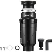
JW301 - Trash can Vevor - Free user manual and instructions
Find the device manual for free JW301 Vevor in PDF.


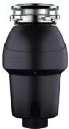
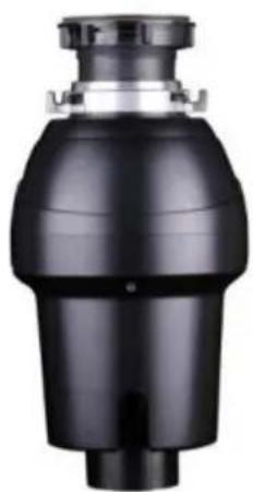
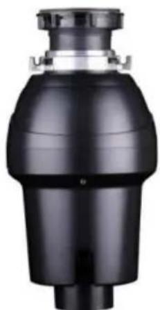
| Product Type | Food Waste Disposer |
| Brand | Vevor |
| Model | JW301 (JW-301) |
| Power Supply | 120 V AC, 60 Hz |
| Rated Power | 1/2 HP (approx. 370 W) |
| Motor Type | DC Motor |
| Installation Mode | Twist Lock |
| Dimensions (H x Ø) | Approx. 30 x 20 cm |
| Weight | Approx. 4 kg |
| Grinding Capacity | Common food waste (bones, peels, coffee grounds) |
| Operation | Continuous feed with switch (or batch feed optional) |
| Anti-Jam | Swiveling anti-jam blades |
| Reset Button | Yes (red, located opposite discharge elbow) |
| Splash Guard | Yes (except Top Control/Batch Feed models) |
| Turntable Material | Stainless Steel |
| Lubrication | None required (permanently lubricated motor) |
| Maintenance | Self-cleaning; do not use chemicals |
| Cleaning | Let cold water run for 15 seconds after grinding |
| Warranty | Electronic warranty via www.vevor.com/support |
| Compliance | Designed for 120 V, 60 Hz; household use |
Frequently Asked Questions - JW301 Vevor
User questions about JW301 Vevor
0 question about this device. Answer the ones you know or ask your own.
Ask a new question about this device
Download the instructions for your Trash can in PDF format for free! Find your manual JW301 - Vevor and take your electronic device back in hand. On this page are published all the documents necessary for the use of your device. JW301 by Vevor.
USER MANUAL JW301 Vevor
Technical Support and E-Warranty Certificate www.vevor.com/support
Garbage Disposal
Model: JW-301 / JW-301DCN / JWM-331 / JWM-331DCN/JWM-V50/JWM-V50A/JW-V50/JW-V50A/JW-731/JW-731DCN/JWM-931/JWM-931DCN
We continue to be committed to provide you tools with competitive price. "Save Half", "Half Price" or any other similar expressions used by us only represents an estimate of savings you might benefit from buying certain tools with us compared to the major top brands and does not necessarily mean to cover all categories of tools offered by us. You are kindly reminded to verify carefully when you are placing an order with us if you are actually saving half in comparison with the top major brands.
VEVOR®
TOUGH TOOLS, HALF PRICE
Garbage Disposal Instruction Manual
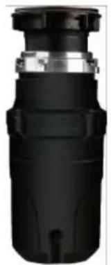
natural_image
Close-up of a black cylindrical electronic component with metallic top and mounting holes (no visible text or symbols)JW-301
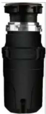
natural_image
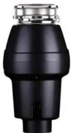
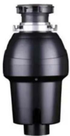
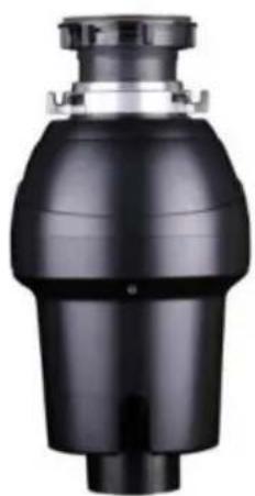
Close-up of a black cylindrical electronic component with metallic top and mounting holes (no visible text or symbols)JW-301DCN
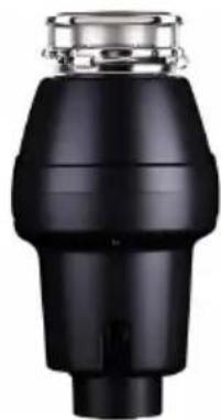
natural_image
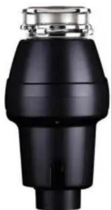
Close-up of a black industrial component with a metallic top (no visible text or symbols)JWM-331
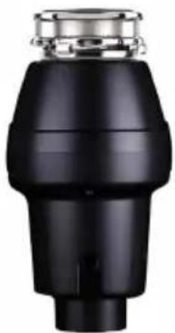
natural_image
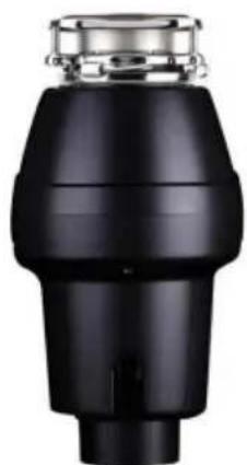
Black industrial component with metallic top and cylindrical body (no visible text or symbols)JWM-331DCN
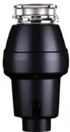
natural_image
Close-up of a black industrial component with metallic top and bottom (no visible text or symbols)JWM-V50
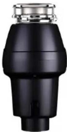
natural_image
Close-up of a black industrial component with metallic top and cylindrical body (no visible text or symbols)JWM-V50A
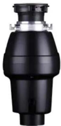
natural_image
Black industrial valve component with no visible text or symbolsJW-V50
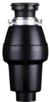
natural_image
Black mechanical component with cylindrical body and flange (no visible text or symbols)JW-V50A
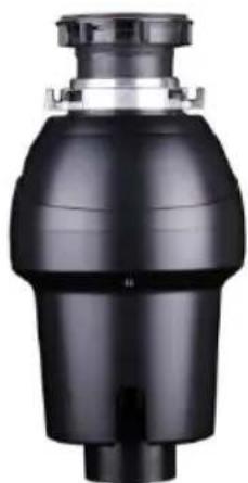
natural_image
Black industrial water tap with a cylindrical tank and inlet pipe (no visible text or symbols)JW-731
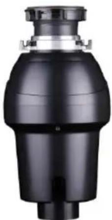
natural_image
Black industrial water tap with a cylindrical tank and flange (no visible text or symbols)JW-731DCN
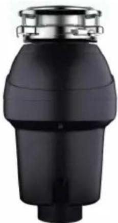
natural_image
Black cylindrical mechanical component with metallic ring and flange (no visible text or symbols)JWM-931
natural_image
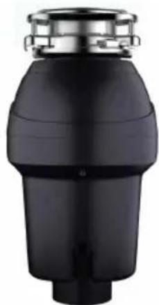
Black industrial exhaust pipe fitting with metallic clamps (no text or symbols visible)JWM-931DCN
NEED HELP? CONTACT US!
Have product questions? Need technical support? Please feel free to us: Technical Support and E-Warranty Certificate www.vevor.com/support
This is the original instruction, please read all manual instruction carefully before operating. VEVOR reserves a clear interpretation user manual. The appearance of the product shall be subject to product you received. Please forgive us that we won't inform you there are any technology or software updates on our product.
Please read this manual carefully before use!
WARNING - When using Food Waste Disposer, basic precautions are alw to be followed, including the following:
1) Read all the instructions before using the disposer.
2) To reduce the risk of injury, close supervision is required when a dispose used near children.
3) Do not put fingers or hands into a disposer.
4) Turn the power switch to the off position before attempting to clear a jar remove an object from the disposer.
5) When attempting to loosen a jam in a disposer, use a long wooden object as a wooden spoon or the wooden handle of a broom or mop.
6) When attempting to remove objects from a disposer use long-handled tong pliers. For a disposer that is magnetically actuated, use nonmagnetic tools.
7) To reduce the risk of injury by materials that are expellable by a dispose put the following into a disposer:
a) Clam or oyster shells.
b) Caustic drain cleaners or similar products.
c) Glass, china, or plastic.
d) Large whole bones.
e) Metal, such as bottle caps, tin cans, or utensils
f) Hot grease or other hot liquids.
8) When not operating a disposer, leave the drain cover in place to reduce of objects falling into the disposer.
GROUNDING INSTRUCTIONS
This disposer must be grounded to reduce the risk of electric shock in the a malfunction or breakdown. Grounding provides a path of least resistance for electric current. This disposer is equipped with a cord having an
equipment-grounding conductor and a grounding plug, The plug must be plugg into an outlet that is properly installed and grounded in accordance with all I codes and ordinances.WARNING - Improper connection of the
equipment-grounding conductor can result in a risk of electric shock Check with qualified electrician or serviceman if you are in doubt as to whether the discharge properly grounded. If the plug provided with the disposer does not fit the output not modify the plug or attempt.
See insert for specific information about your new disposer
Plug Controller into the wall Once you have properly attached power cord to connector, plug your heated pad into the wall.
NOTE:
This Food Waste Disposer has been designed to operate on 120/240 Volt, 6 Hz exclusively.
Using any other voltage or Hz adversely affects performance.
IMPORTANT:
Read all instructions thoroughly, Keep this guide for future reference.
CAUTION:
Be sure to review SAFETY INSTRUCTIONS FIRST PERTAINING TO A RISK FIRE, ELECTRICAL
SHOCK OR INJURY TO PERSONS before using disposer.
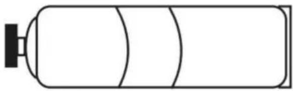
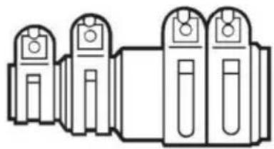
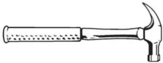
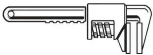
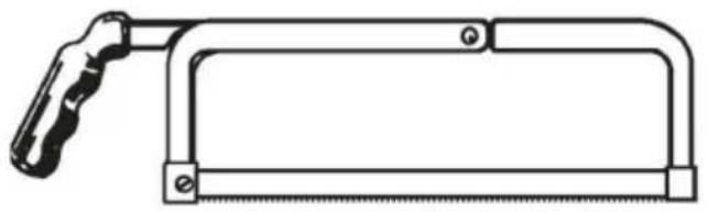
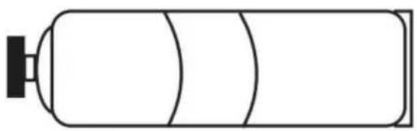
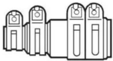
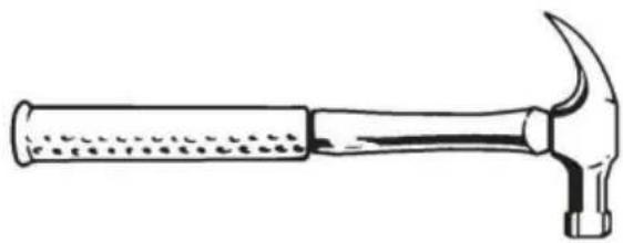
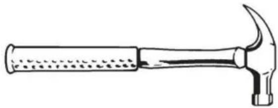
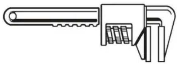
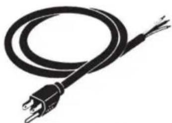
Tools and materials you may need

natural_image
Line drawing of a screwdriver with a flat blade and hexagonal end (no text or symbols)PHILLIPS & FLATBLADE SCREWDRIVER
natural_image
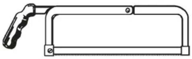
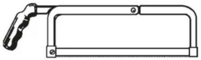
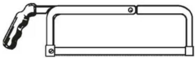
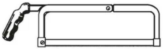
Line drawing of a hand saw with metal handle and blade (no text or symbols)HACKSAW
natural_image
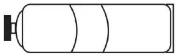
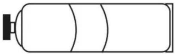
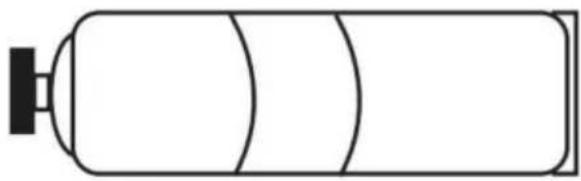
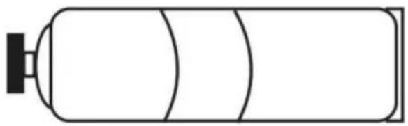
Simple line drawing of a cylindrical object with a protruding knob (no text or symbols)PLUMBER'S PUTTY
natural_image
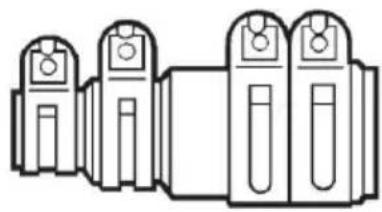
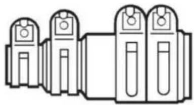
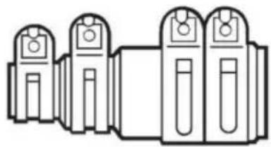
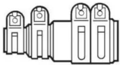
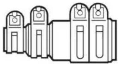
Pure line drawing of four identical mechanical components without any text, numbers, or symbolsDISHWASHER CONNECTOR KIT
natural_image
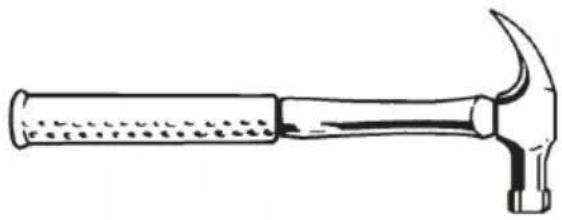
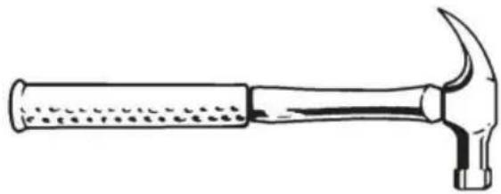
Line drawing of a hammer with textured handle and curved head (no text or symbols)HAMMER
natural_image
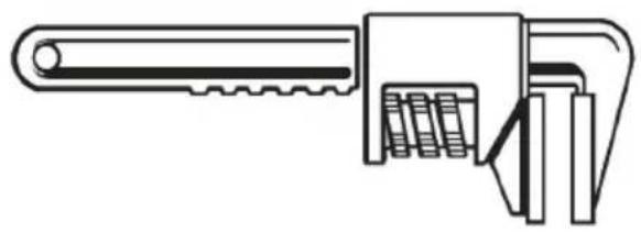
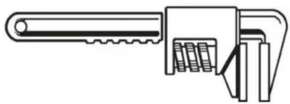
Line drawing of an adjustable wrench tool (no text or symbols present)PIPE WRENCH

DOW EL OR
STEEL PUNCH
natural_image
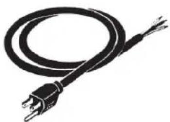
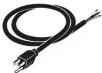
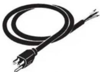
Black and white illustration of a coiled electrical plug with terminal leads (no text or symbols)POWER CORD
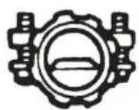
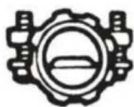
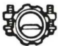
STRAIN RELIEF
IMPORTANT SAFETYINSTRUCTIONS
INSTRUCTIONS PERTAINING TO A RISK OF FIRE, ELECTRIC SHOCK OR INJURY TOPERSONS. SAVE THESE INSTRUCTIONS.
WARNING - When using electrical appliances, basic precautions should always
followed, including the following:
- Read all instructions before using the appliance.
-
To reduce the risk of injury, close supervision is necessary when an applied near children.
-
Do not put fingers or hands into a waste disposer.
-
Turn the power switch to the off position before attempting to clear a jan remove an object from the disposer.
-
When attempting to loosen a jam in a waste disposer, use a long wooden such as a wooden spoon or the wooden handle of a broom or mop.
-
When attempting to remove objects from a waste disposer use long-handle tongs or pliers. If the disposer is magnetically actuated, non-magnetic tools sh be used.
-
To reduce the risk of injury by materials that maybe expelled by a waste disposer, do not put the following into a disposer: clam or oyster shells; caust drain cleaners or similar products; glass china or plastic; large whole bones; such as bottle caps, tin cans, aluminum foil or utensils; hot grease or other liquids; whole cornhusks.
-
When not operating a disposer, leave the stopper in place to reduce the objects falling into the disposer.
-
DO NOT operate disposer unless splash guard is in place. (Does not app the Top Control/Batch Feed units.)
-
For proper grounding instructions see the ELECTRICAL CONNECTION portion of this manual.
1. REMOVAL OF OLD UNIT
TYPICAL INSTRUCTIONS, YOUR MODEL MAY VARY.
Before starting this step, turn off electrical power at the circuit breaker or fuse. If your old mount is the same as the mount on your new disposer, just rev assembly instructions found in section 3. If your new mount system is different follow these instructions:
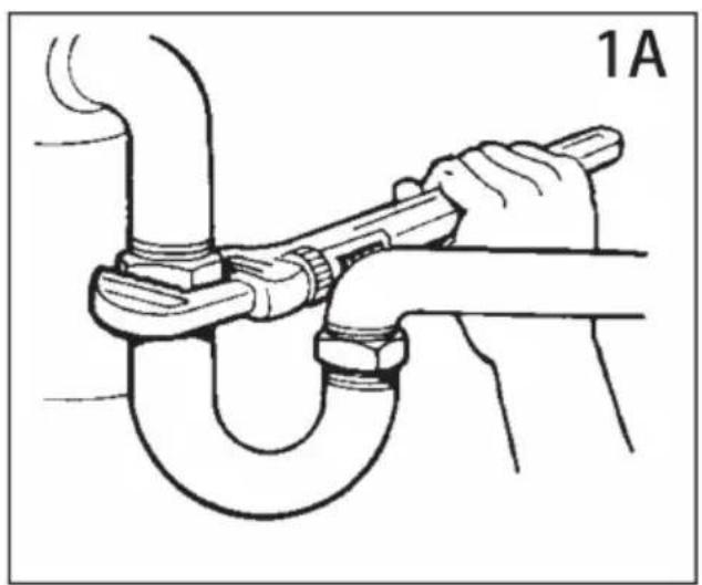
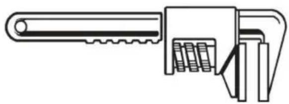
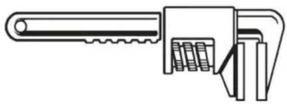
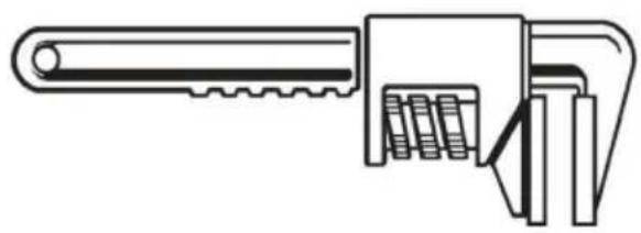
A. Use a pipe wrench to disconnect drain line where it attaches to disposer discharge tube (see 1A).
B. Remove disposer from sink flange by turning mount ring to the left clock
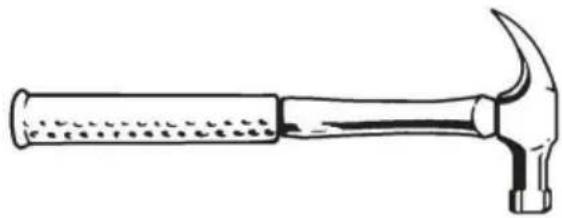
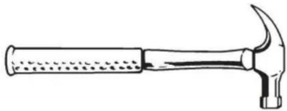
(see 1B). If you are unable to turn the mount ring, tap on one of the exten from the ring with a hammer. Some mounting systems have tubular extensions. Inserting a screwdriver into one tube will provide additional leverage for turning mount ring (see 1B). Some disposers may require the removal or loosening of from the mount screws (see 1C). Some disposers may require the removal clamp.
Caution: Be sure to support the disposer while performing this step or it may when the mounting ring is disconnected from the mounting assembly. If your disposer is hard wired (metal shielded cable not utilizing a wall plug), complete steps C and D. If you utilize a plugin cord, go on to step E.
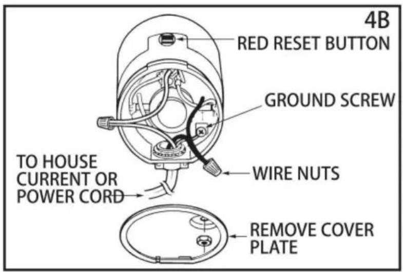
C. When disposer is removed, turn up side down and remove electrical cove plate(see 1D).
D. Use screwdriver to remove green ground wire. Remove wire nuts from black and white power wires and separate disposer wires from power cable wires. Loosen screws on cable clamp and separate cable from disposer.
E. To remove remaining mount system from the sink, loosen mount screws, put mount ring up. Under it is the snap ring. Use screwdriver to pop off ring (see Remove mount ring, protector ring and gasket from sink flange. Some mounts require the unscrewing of a large ring holding the sink flange in place. Pull flange up through sink and clean off old putty from sink.
IMPORTANT: Unless you have a new home, this is a good time to clea the trap and drain lines by running a drain auger or plumber's snake b installing your new disposer.
natural_image
Diagram of a pipe connection with a hand holding a tool, labeled '1A' (no text or symbols on the diagram itself)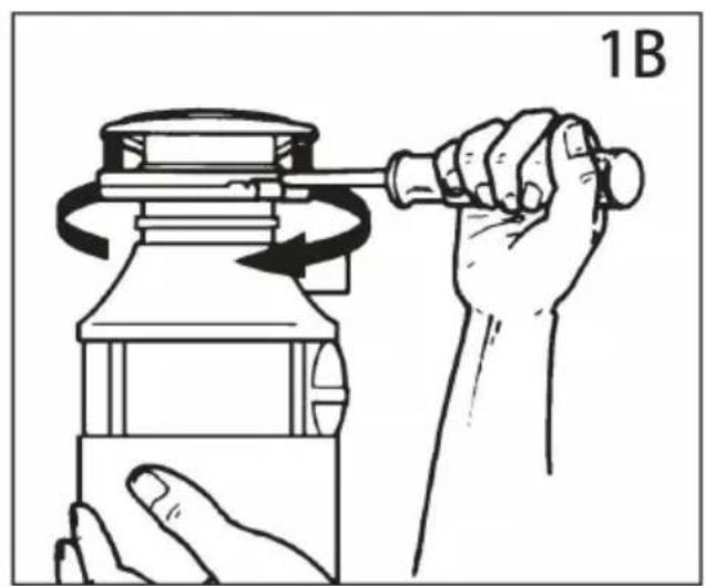
natural_image
Line drawing of a hand using a hammer to press a mechanical component, no text or symbols present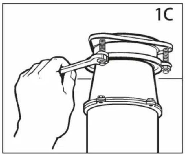
natural_image
Line drawing of a hand using a tool to lift a mechanical component (no text or symbols)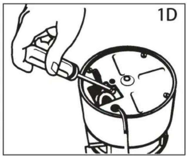
natural_image
Illustration of a hand using a tool to adjust or install a mechanical component, no text or symbols present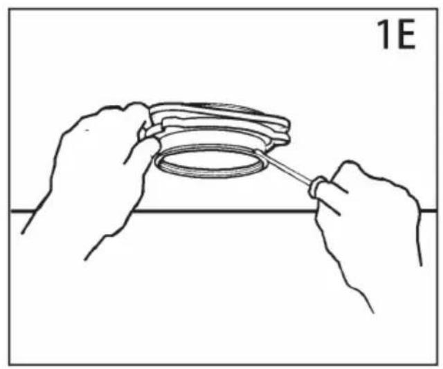
natural_image
Line drawing of hands holding a circular object with a tool, no text or symbols present2. DISHWASHER CONNECTION
If you are utilizing a dishwasher, complete the following procedure. if dishwas not to be connected go on to section 3.
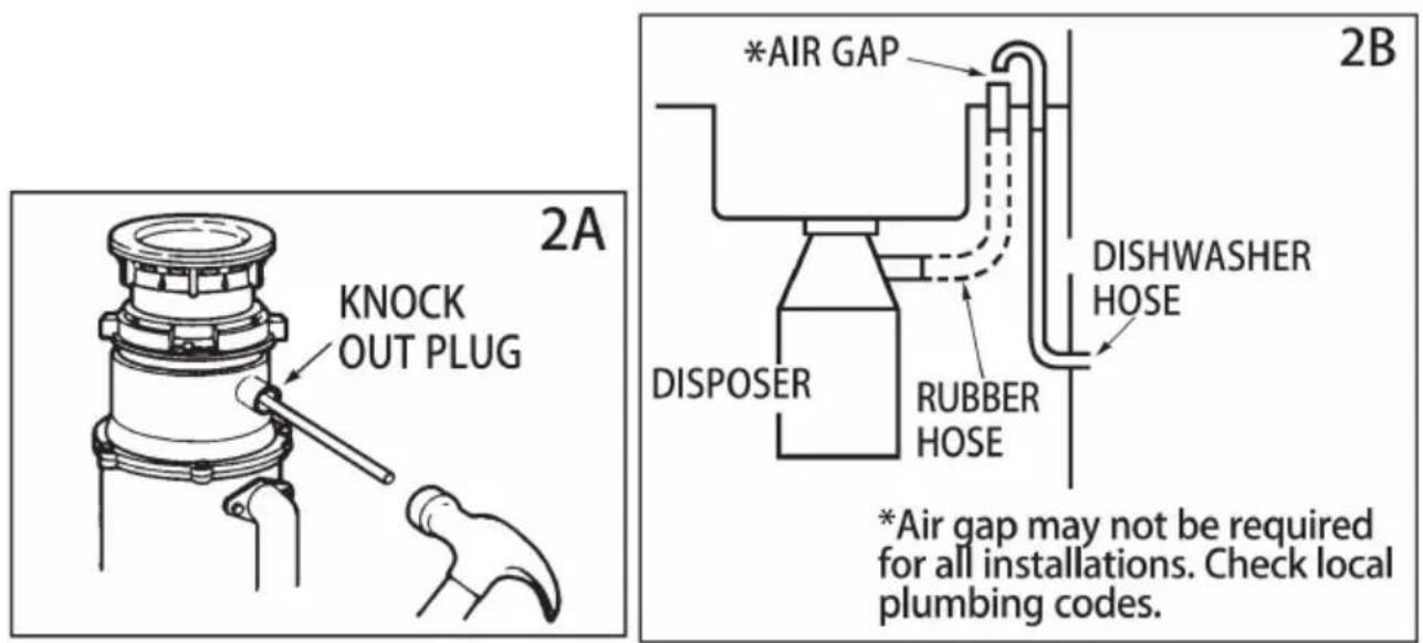
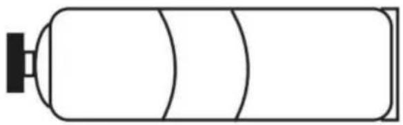
A. Using a blunt instrument (steel punch or wooden dowel), knock out entire (see 2A). Do not use a screwdriver or sharp instrument. When knockout plug into disposer, you may remove it or simply grind it up when the disposer is used. This will not damage the disposer in anyway, but may take some time grind, over the course of several uses. Go to Section 3.
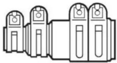
B. Connect dishwasher hose using hose clamp. If hose size is different, you need a Dishwasher Connector Kit (see 2B). Make sure all plumbing connection are tight and in accordance with all plumbing codes and ordinances. Run wa and check for leaks.
3. INSTALLATION OF MOUNTING ASSEMBLY
YOUR DISPOSER COMES WITH ONE OF THE FOLLOWING MOUNT SYSTEMS
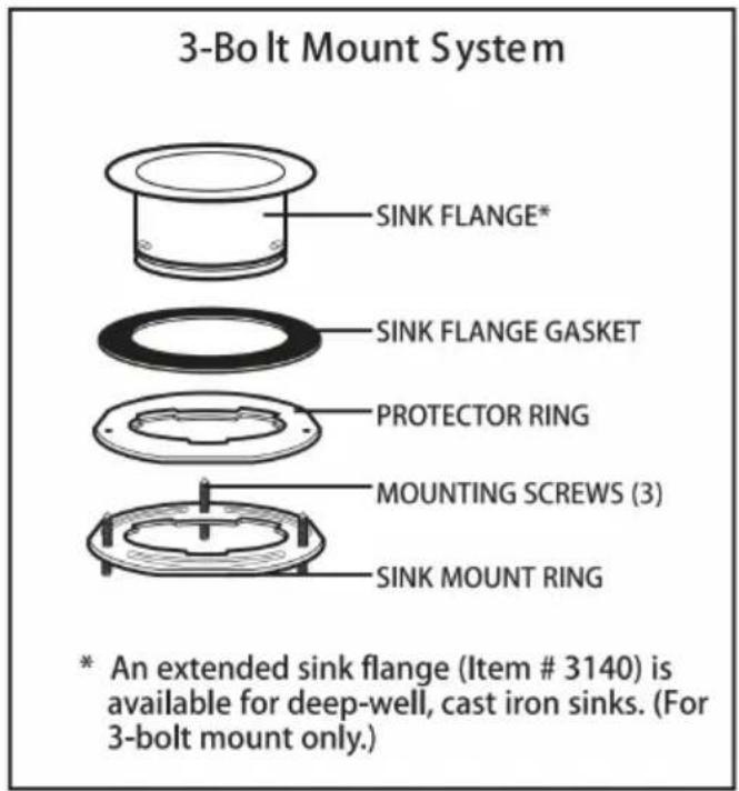
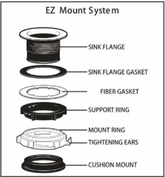
Proceed to the instructions for your type of mount system.
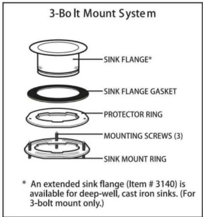
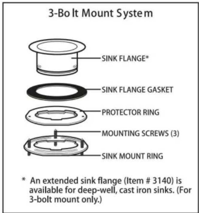
3-Bolt Mount System
READ COMPLETELY BEFORE STARTING
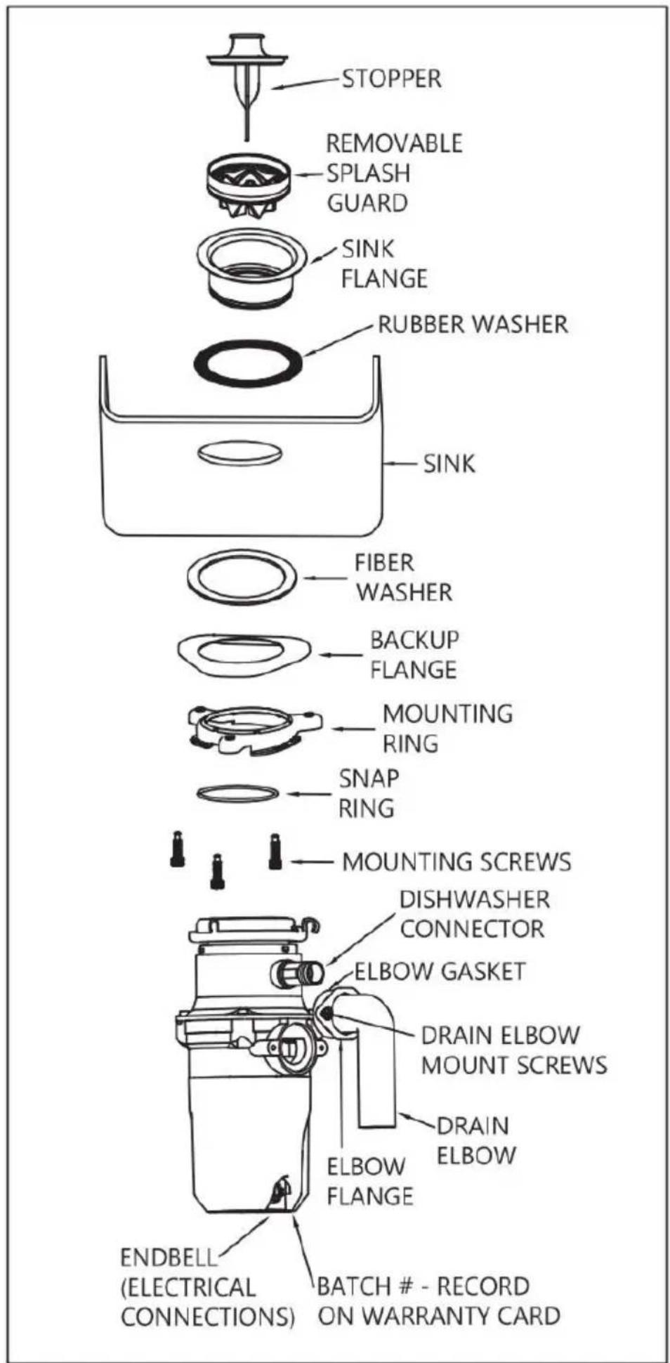
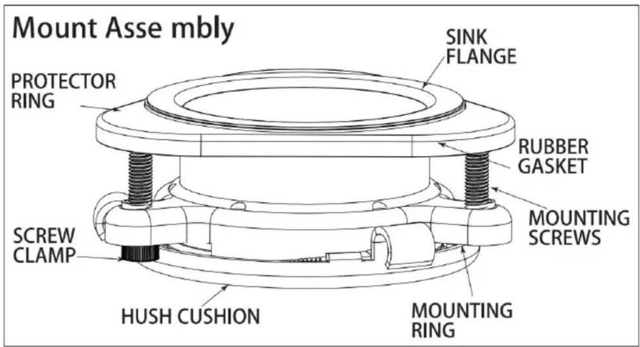
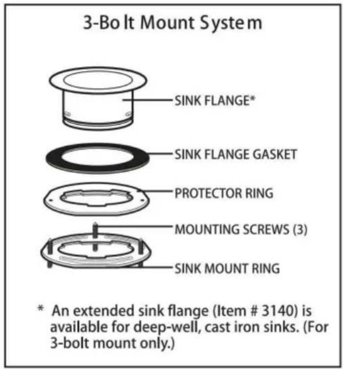
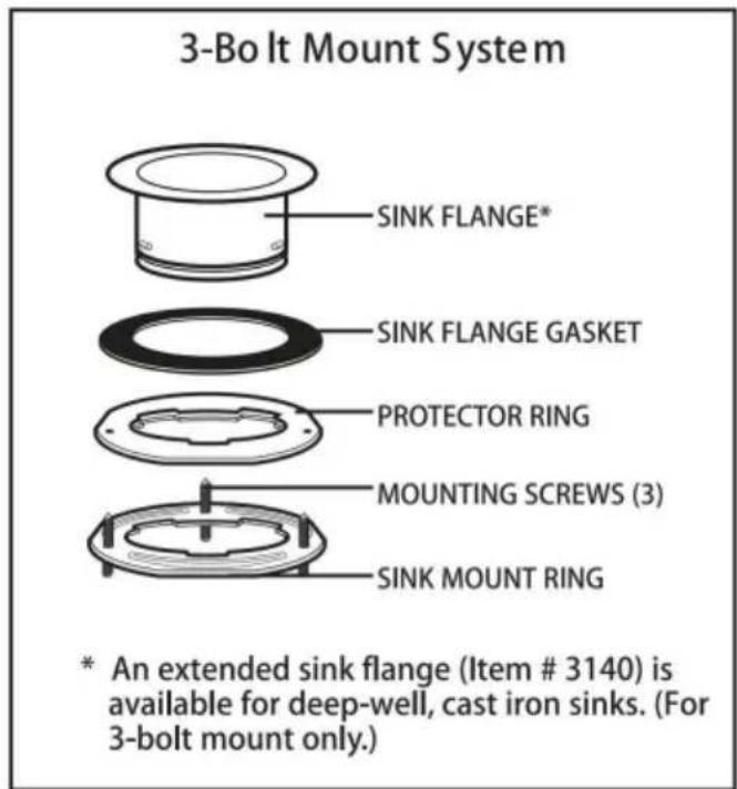
NOTE: Pay close attention to the order of mount assembly parts, as they have been correctly assembled by the factory. (See 3A and 3B.)
A. Disassemble the mounting assembly, as it has been shipped, by turning the sink flange until the projections align with the notches in the mount ring and you to pull the sink flange up and out of the remaining mount assembly. No sequence of these parts as they are stacked and refer to 3A and 3B to ide each part. Unpack the 3 mount screws and screw them half way through the mount ring (notice “THIS SIDE UP” is imprinted on top of the mount ring). No stack the rubber gasket on top of the protector ring and sit them on top of pointed ends of the mount screws.
B. Keep these assembled parts together and set aside. Before you connect the disposer to the mount assembly under the sink, you may want to practice engaging the groove of the Hush Cushion to the ridge at the bottom of the flange (see3A and read Sec. 6).
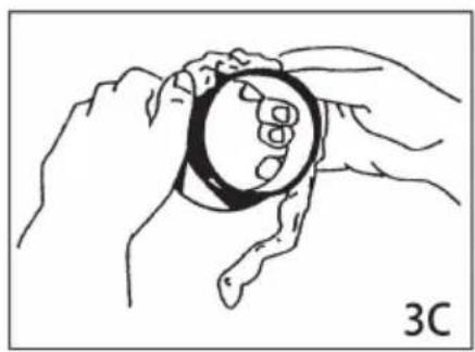
C. Be sure your sink is clean. Pack the underside rim of the sink flange with plumber's putty (see 3C) Position the sink flange so it is centered and read at you look into your sink. Push the sink flange firmly into the sink opening to good seal. DONOT move or rotate the sink flange once seated or the seal broken.
D. Take the remaining portion of the mount assembly, as it was set aside a make sure that the rubber gasket is on top of the protector ring. From under sink, while holding the sink flange firmly with one hand, line up the notches mount ring with the projections of the sink flange. Slide the mount assembly onto the sink flange, past the projections and give the mount assembly a 1/4 so that it will hang by itself (see 3D).
E. Tighten the 3 mounting screws evenly with a screwdriver (see 3E). DO N OVERTIGHTEN! Trim off excess putty.
natural_image
Line drawing of two hands holding a circular object with a magnified inset showing internal features (no text or symbols)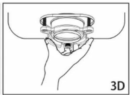
natural_image
Line drawing of a hand holding a 3D-printed mechanical component (no text or symbols)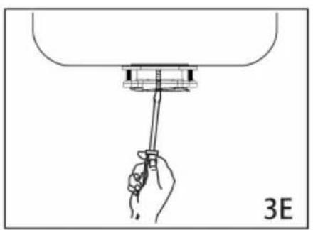
natural_image
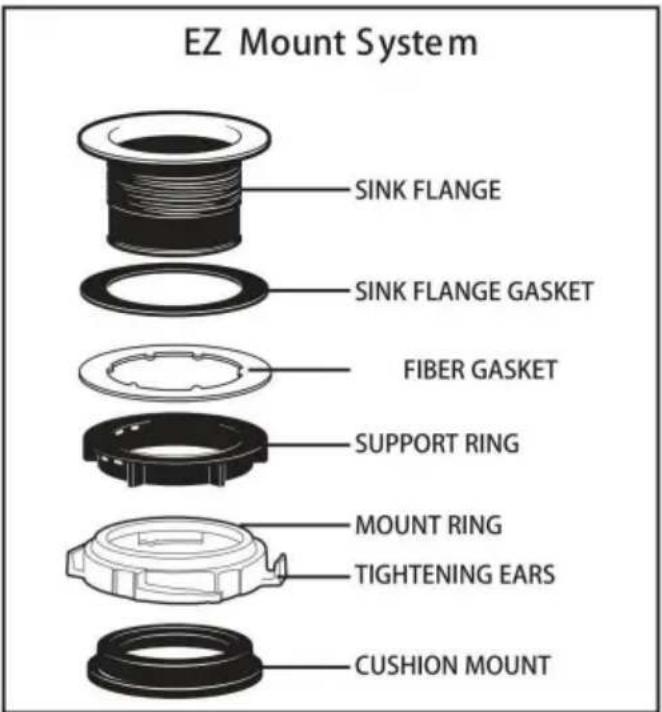
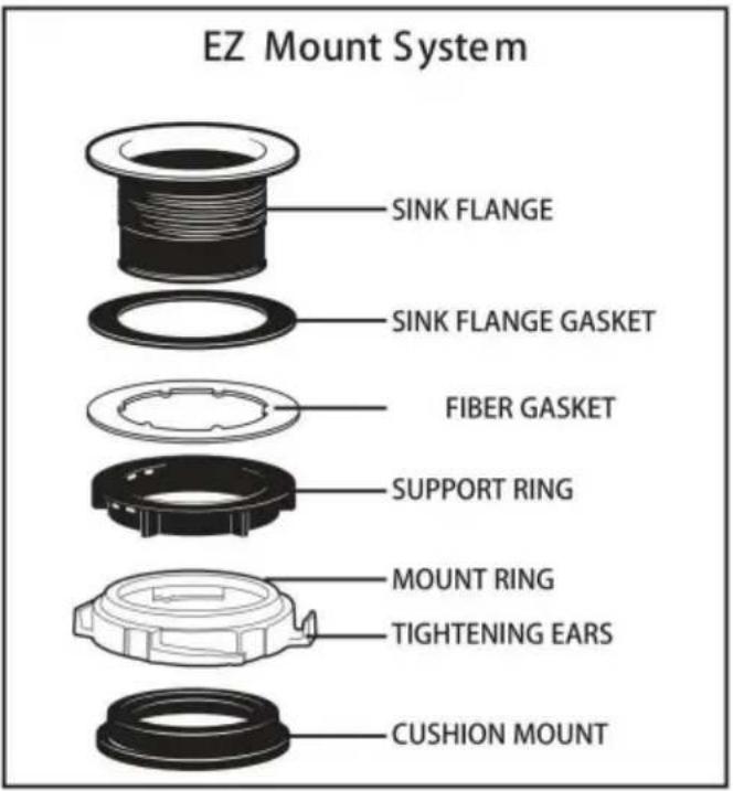
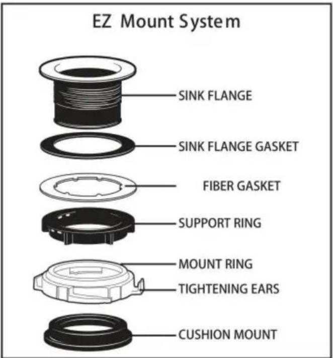
Line drawing of a hand holding a tool above a mechanical component, labeled '3E' (no text or symbols on the diagram itself)EZ Mount System
READ CO MPLETELY BEFORE STARTING
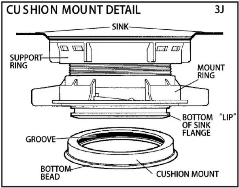
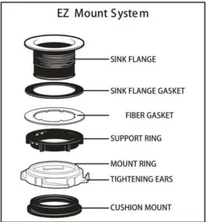
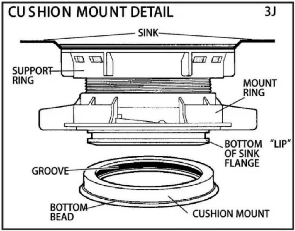
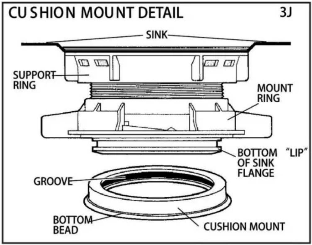
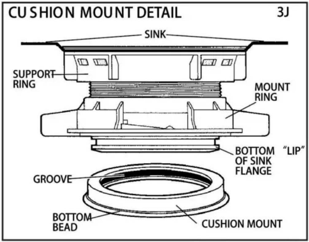
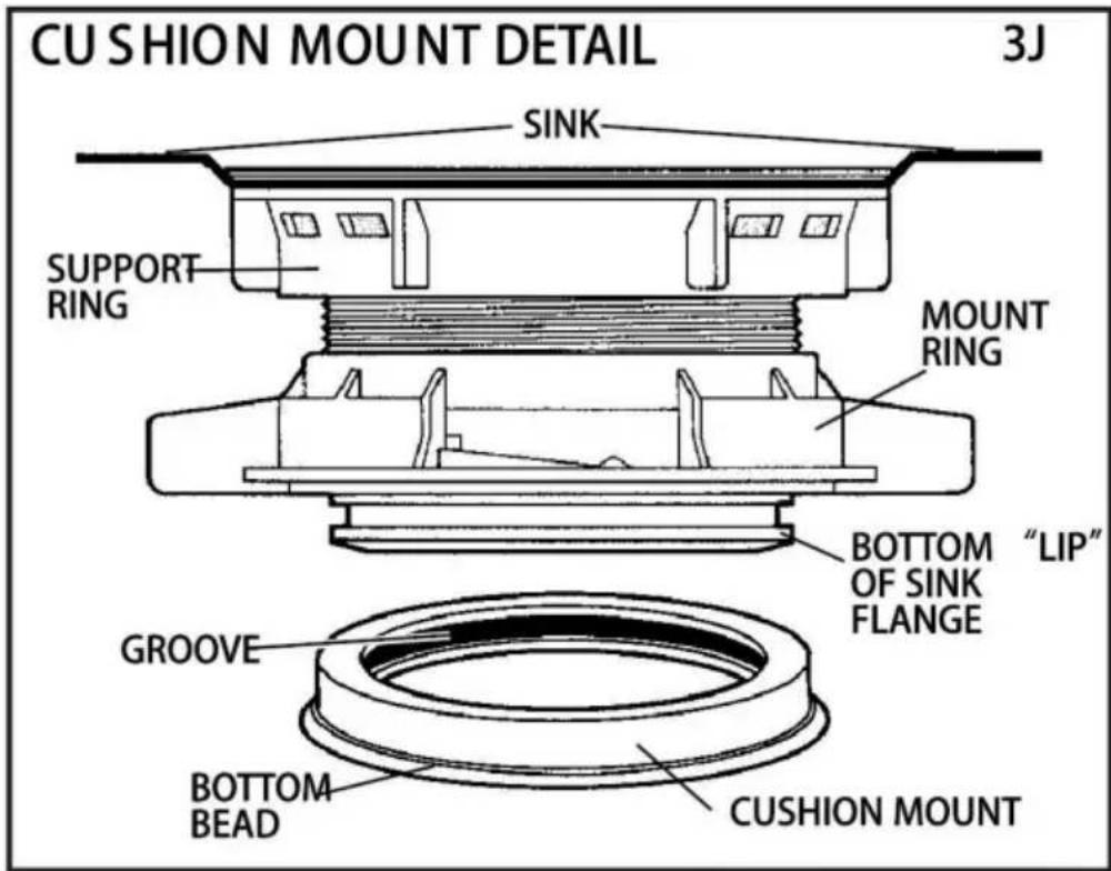
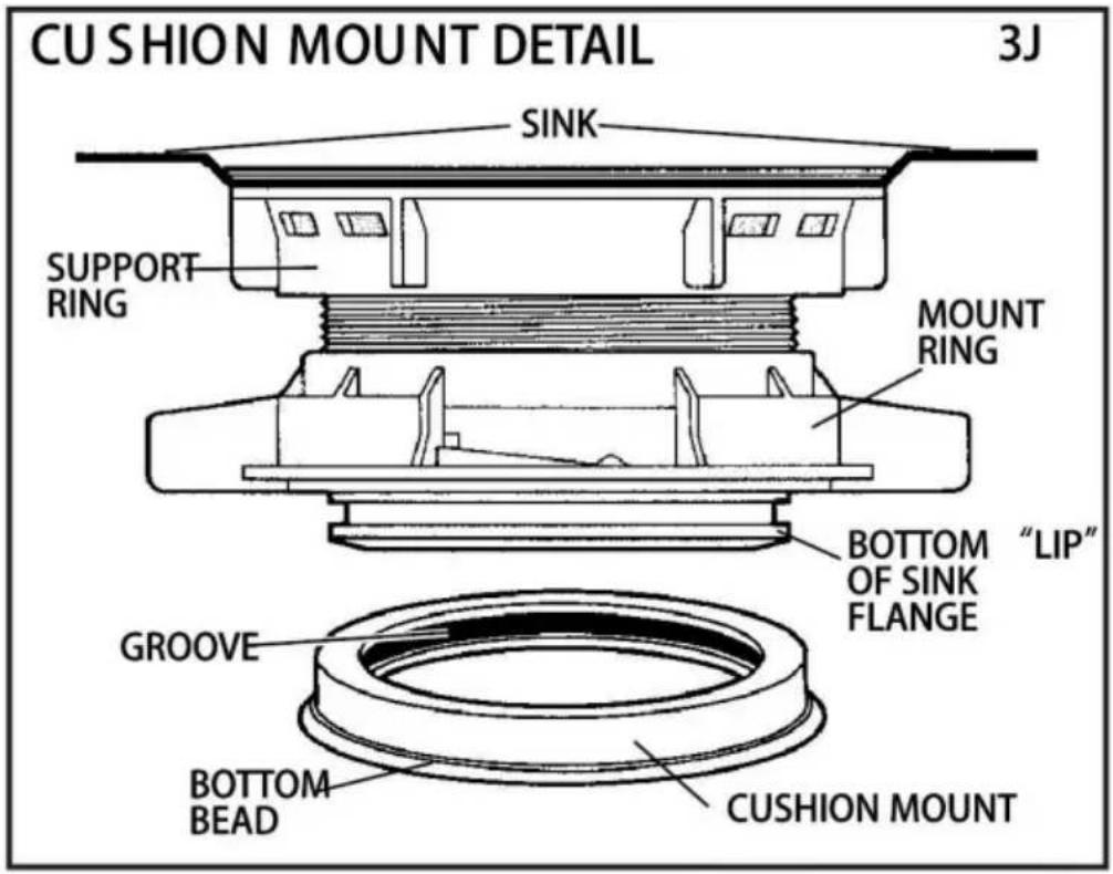
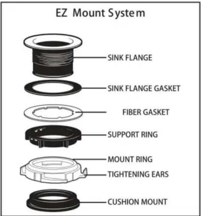
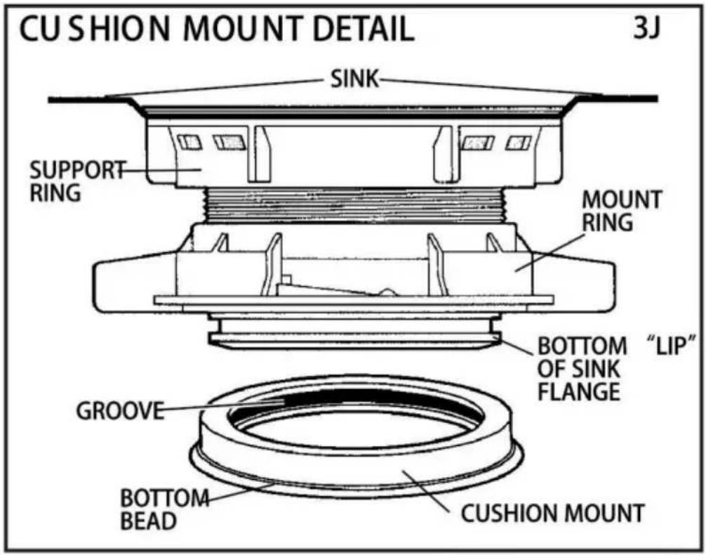
NOTE: Pay close attention to the order of mount assembly parts, as they have been correctly assembled by the factory. Also, reference the cushion mount d in illustration 3J below for the proper orientation of the cushion mount.
NOTE: Try practicing this assembly before you get under the sink to get the of how the parts fit together.
A. Disassemble mount assembly from disposer by turning mount ring to the I (clockwise) and remove.
B. Raise mount ring toward top of sink flange. Remove cushion mount. Remove mount ring. You may want to practice installing the cushion mount at this point before you are under the sink. See paragraph H. Also see the "Important No Cushion Mount Detail."
C. Unscrew support ring from sink flange and remove fiber gasket. You are left with sink flange and rubber gasket.
D. The rubber gasket is used instead of plumbers putty with stainless steel: Other sinks will require putty.
E. If no putty is used, insert sink flange through rubber gasket into sink open. Do not rotate sink flange once it is seated.
F. If you use putty instead of the gasket, form a ring around underside of flange. Insert flange into sink opening, press down hard to squeeze out excess putty. From under sink, trim off excess putty flush with bottom edge of sink opening.
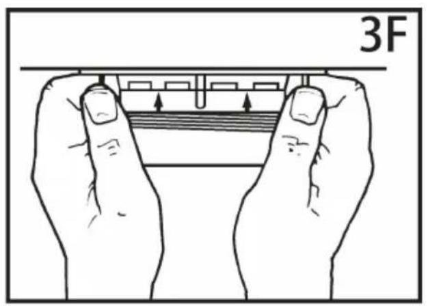
G. From underneath sink, slip fiber gasket onto exposed sink flange. With an pointing up, screw support ring onto the sink flange, hand tighten until the sink flange will not move (see3F). At this point you may want to insert stopper in and fill with water to check sink flange sea and insure there are no leaks.
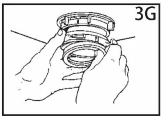
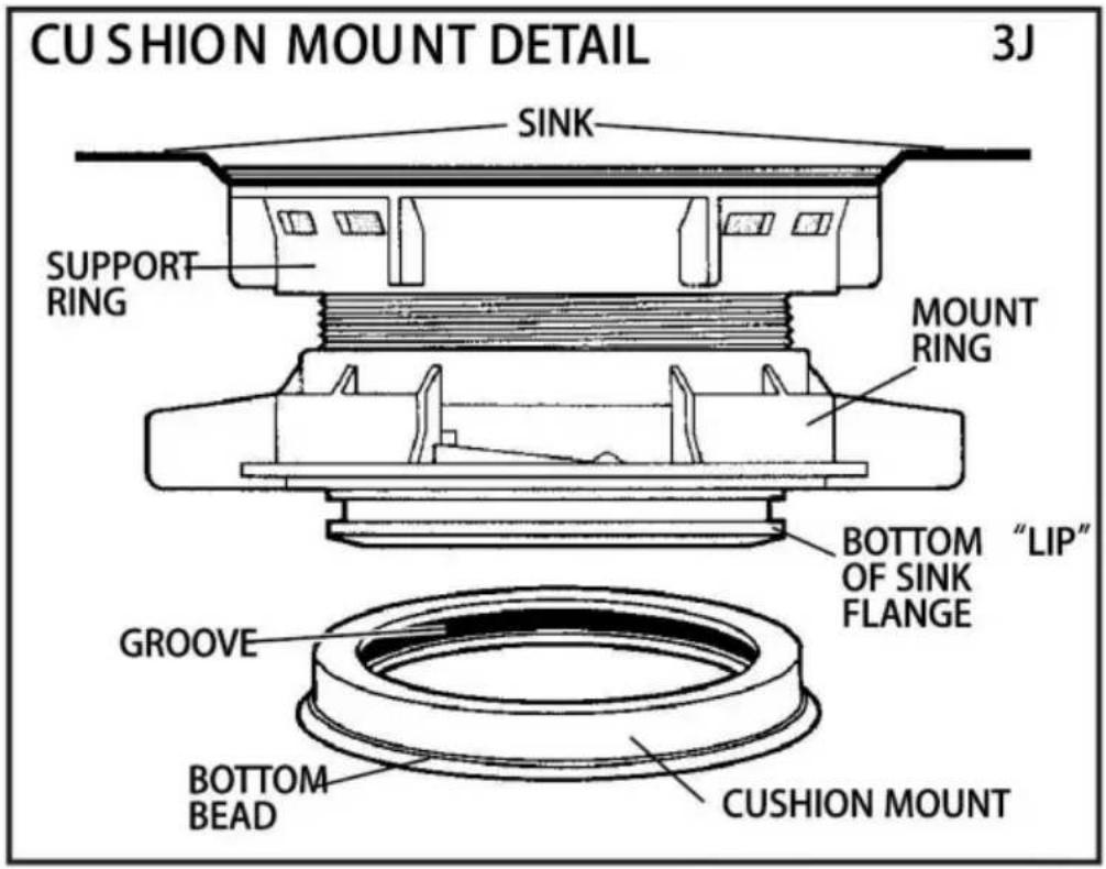
H. Place mount ring over sink flange and hold in place while installing cushi mount (large side down) so the groove on the inside of cushion mount fits on sink flange, similar to putting the lid on a plastic container (see3G,3H & Please read important notice below.
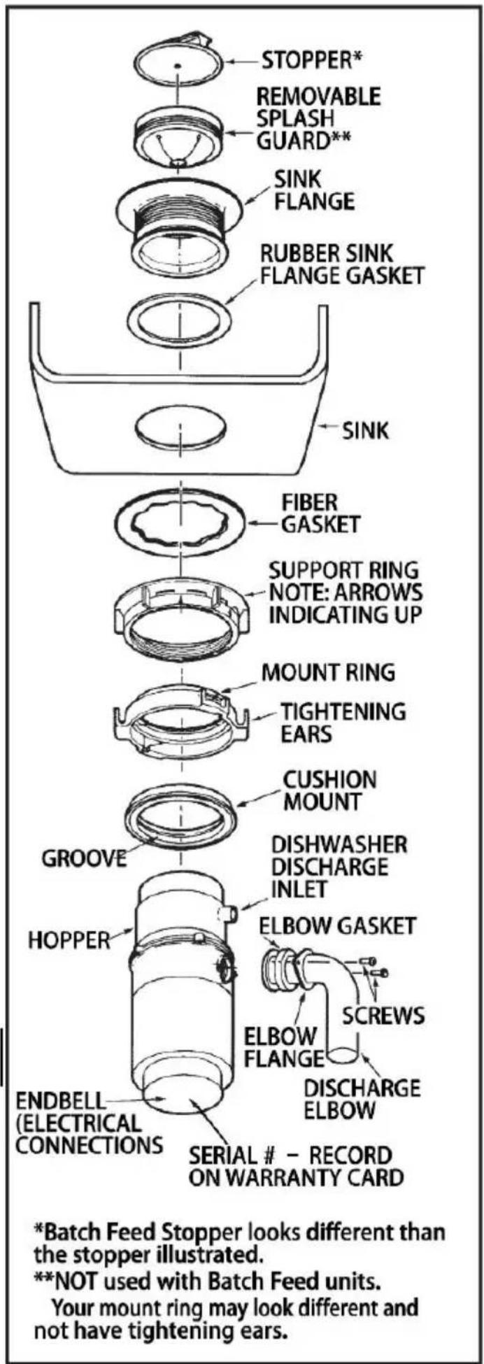
IMPORTANT NOTICE: CUSHION MOUNT DETAIL
When the cushion mount is installed correctly, the lip of the s ink flange fits groove on the inside of the cushion mount and mount ring can be pulled down over cushion mount and will be free to rotate. The bottom bead of the cushion mount acts as a gasket between the bottom of the s ink flange and the t dispose r. See illustration 3J.
natural_image
Illustration of hands assembling a mechanical component labeled '3G' (no text or symbols on the diagram itself)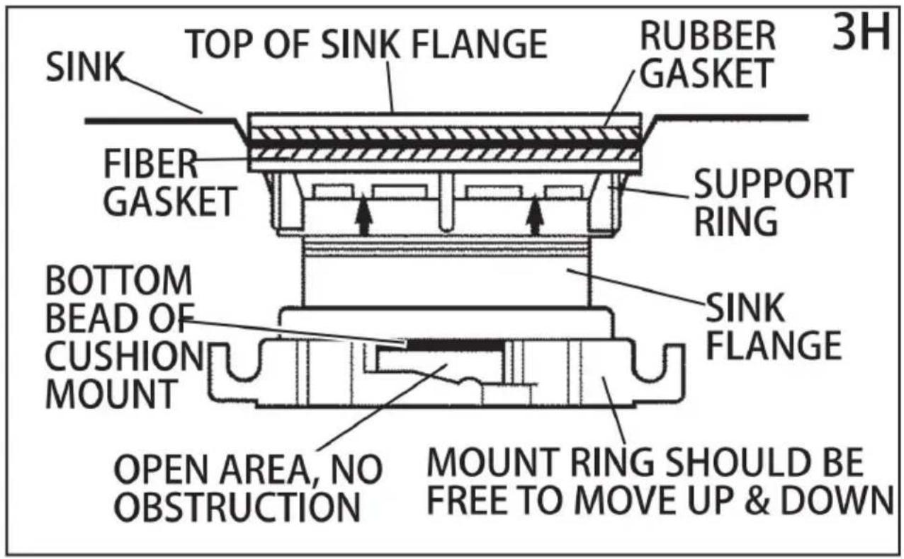
4. ELECTRICAL CONNECTIONS
Now is the time to record the SERIAL NUMBER (locate d on the bottom, dispose r) onto the warranty card.
IF YOU ARE NOT FA MILIAR WITH ELECTRICAL POWERA NDPROCEDURE CALLA QUALIFIED ELECTRICIAN
WARNING: IMPROPER CO NNECTIO N OF THE EQUIP MENTGROU NDINGCO NDUCTOR CA N RE SULTIN A RISK OF ELECTRIC SHOCK. C WITH AOUALIFIED ELECTRICIAN OR SERVICE MANIF YOU AREI N DOUBT S TOWHETHER THE APPLIA NCEIS PROPERLY GROU NDED.DO NOT MODIFY THEPLUG PROVIDED WITH THE APPLIA NCE IF IT WILL NOT FIT THE OUTLET, HAVE A PROPER OUTLETI INSTALLED BY A QUALIFIED ELECTRICIAN.
GROUNDING INSTRUCTIONS
FOR WA STEDISPOSER S EQUIPPED WITH AGROU NDED PLUG-IN POWE CORD.
Never use this warming product with:
This appliance must be grounded. In the event of a malfunction or breakdown grounding provides a path of least resistance for electric current to reduce th of electric shock. This appliance is equipped with a cord having an equipment-grounding conductor and a grounding plug. The plug must be plugg into an appropriate outlet that is properly installed and grounded in accordance with all local codes and ordinances.
FOR WA STE DI SPOSER S NOT EQUIPPED WITH AGROU NDED PLUG-I POWER CORD.
This appliance must be grounded. In the event of malfunction or breakdown, grounding provides a path of least resistance for electric current to reduce the path of electric shock. The power cord (to be installed) must have an equipment grounding conductor and a grounding plug. The plug must be plugged into an appropriate outlet that is properly installed and grounded in accordance with a local codes and ordinances.
Disconnect electric power to disposer circuit before installation. Turn the circuit breaker to the OFF position or remove the fuse.
A. Connect disposer to 110-120 Volt, 60 Hz AC current only.
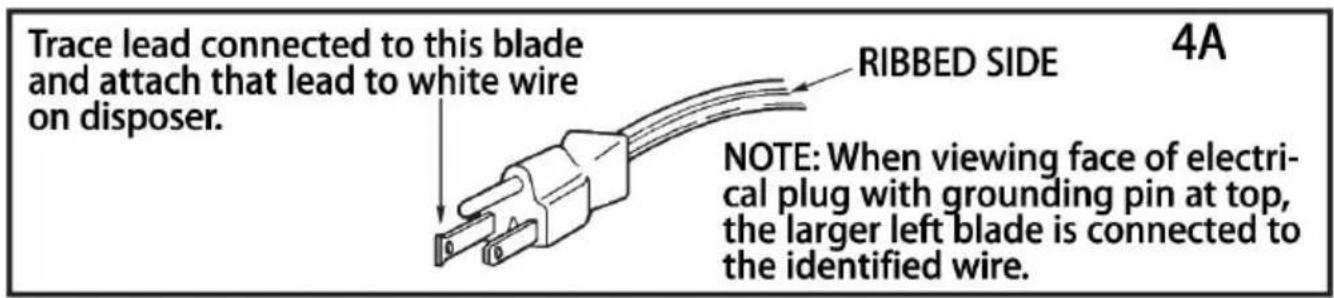
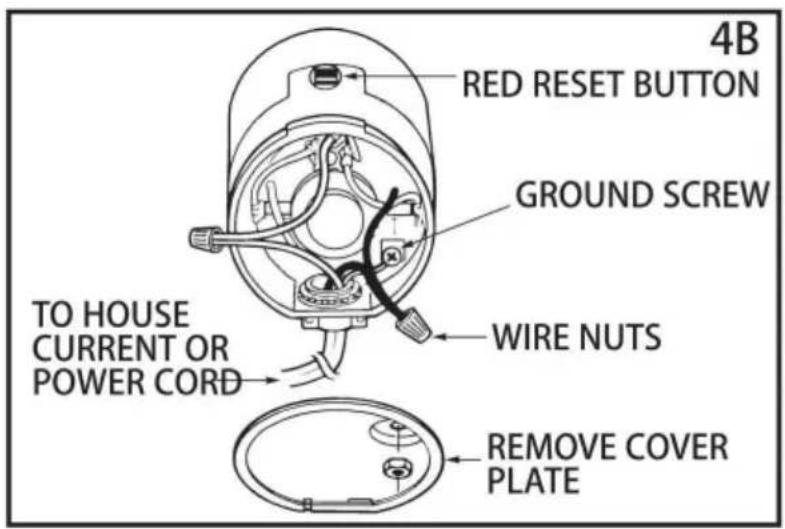
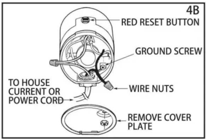
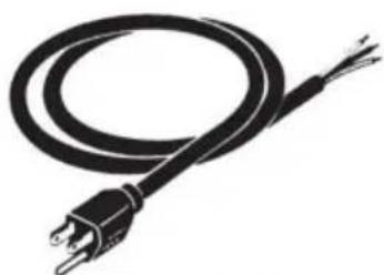
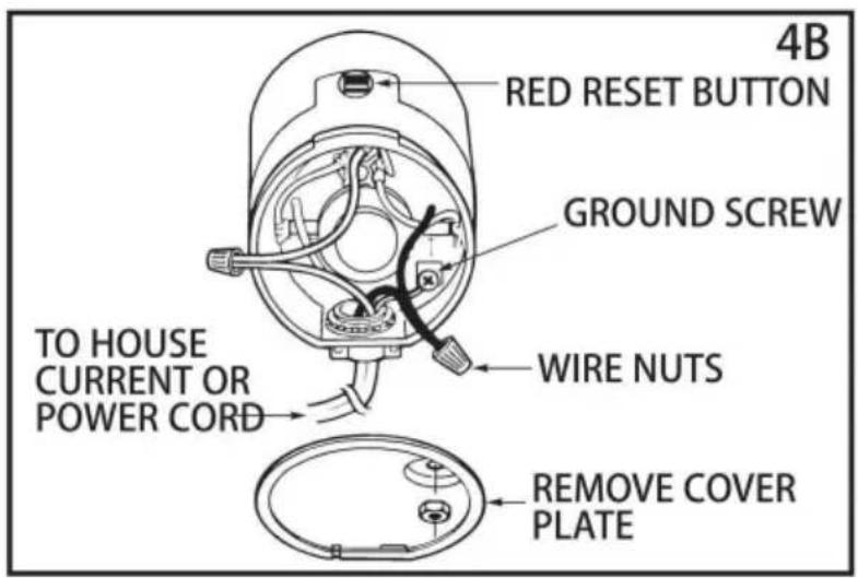
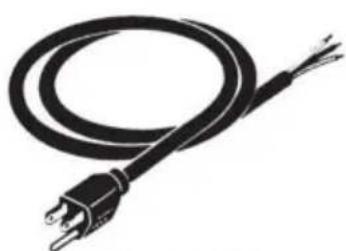
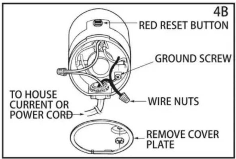
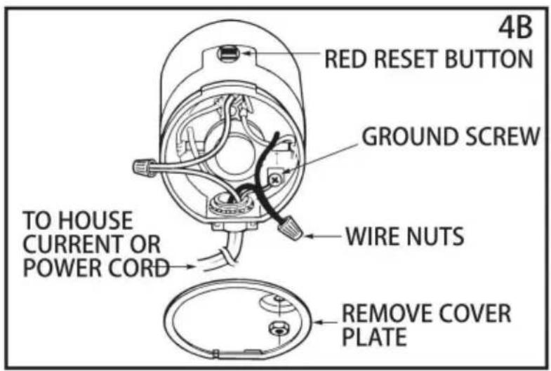
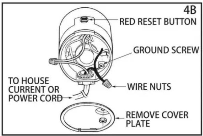
B. If plug-in cord is used, use a three prong plug (see 4A). Ground wire sh attached to the ground screw in the bottom of the end bell (see 4B).
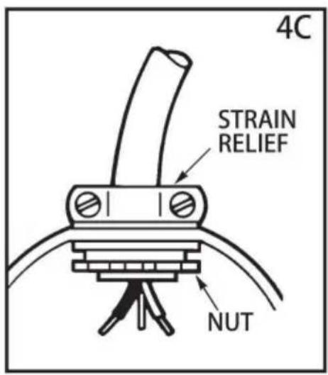
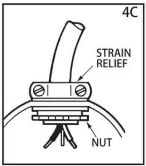
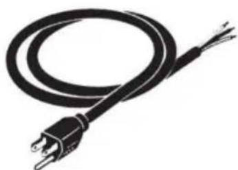
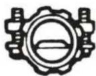
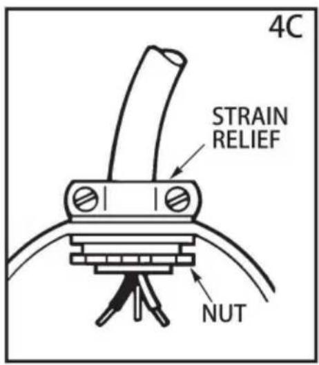
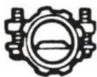
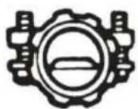
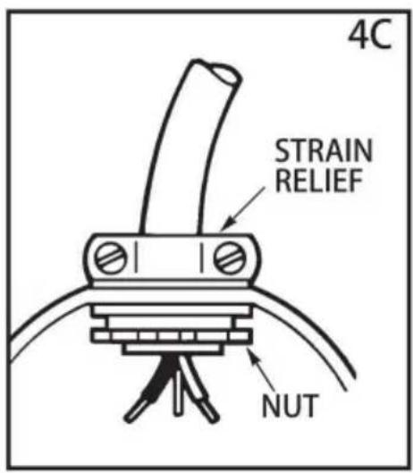
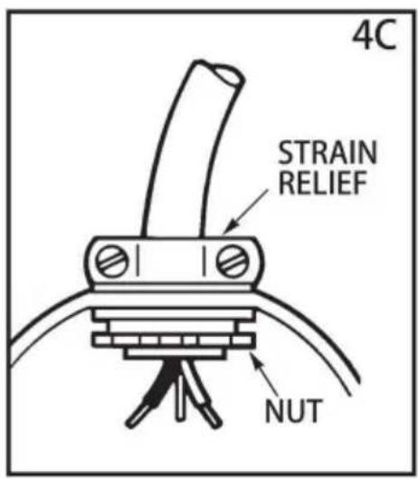
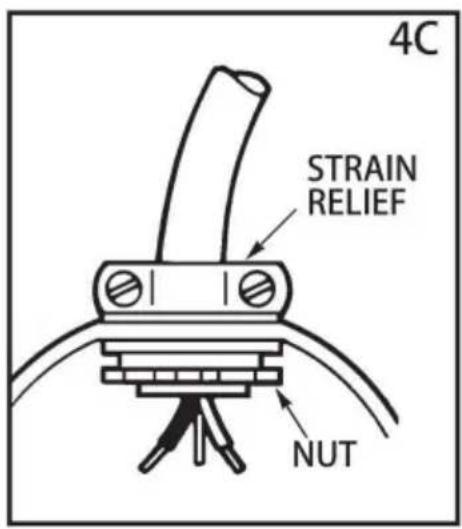
C. Use a cable clamp strain relief connector where power cord enters the disposer (see 4C).
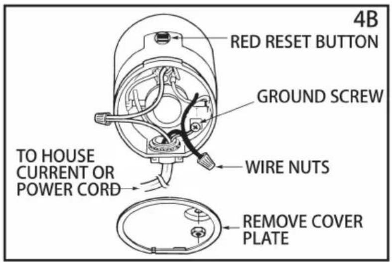
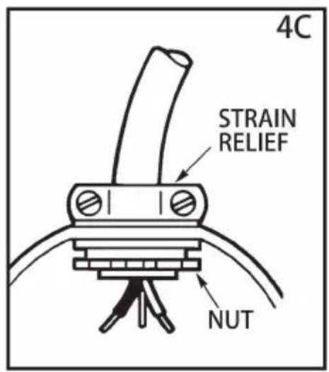
Wiring Disposer Directly to House Current This appliance must be connected grounded, metal permanent wiring system or an equipment. grounding conduct must be run with the circuit conductors and connected to the equipment-ground terminator or lead on the appliance.
A. If you use BX cable:
- install cable connector in hole.
- Connect white wire to white lead of disposer.
- Connect black.
- Connect bare ground.
If BX cable is not used, provide a separate ground wire to nearest cold wall pipe or other suitable ground, using the screw in the bottom of the end bel ground wire (see 4C).
B. If your power supply does not include a ground wire, you must provide it unless metal cable is used. Attach a copper wire securely to disposer ground screw and attach other end of wire to a metal cold water pipe. Use only U approved ground clamp. If plastic pipe is used in your home, a qualified electronic should install a proper ground.
5. ATTACHING DISCHARGE ELBOW
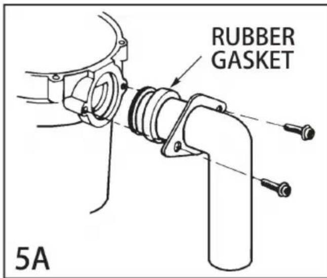
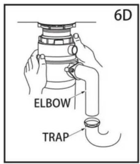
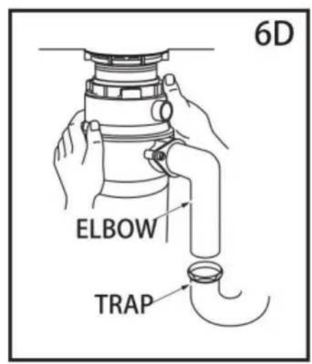
A. Connect waste elbow to the disposer (see 5A), proceed to step 6 and the connect bottom of the elbow by tightening the slip nut (see 5B).
B. If you are connecting to a dishwasher, return to section 2B. If not, make support plumbing connections are tight and in accordance with all plumbing codes and
ordinances. Run water and check for leaks.
natural_image
Line drawing of a hand using a wrench to adjust a U-shaped pipe fitting (no text or symbols)6. CONNECTING DISPOSER TO MOUNT ASSEMBLY
3-BOLT MOUNT(See section 3 for your mount type.)
A. Press firmly around the Hush Cushion to ensure it is engaged with the r the disposer.
B. Lubricate the top inside lip of the rubber Hush Cushion with a liquid soa
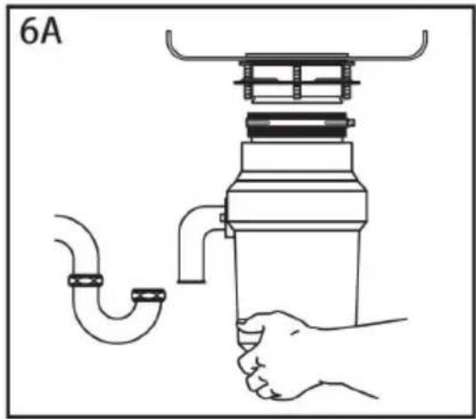
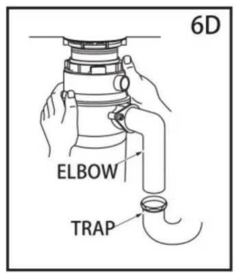
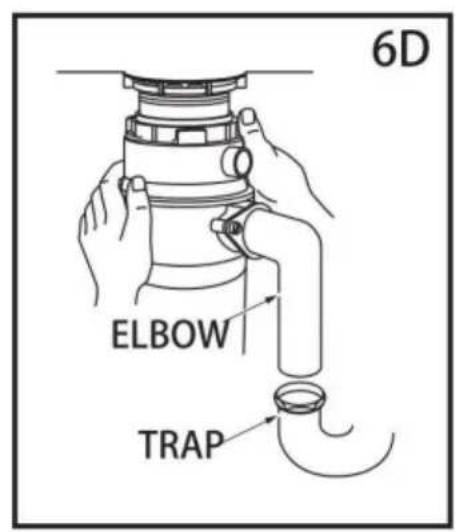
C. Line up discharge elbow of disposer with trap under mounting assembly. It displays disposer up and engage the groove of the Hush Cushion around the ridge at bottom of the sink flange (see 6A& refer back to 3B). While still supporting dis-poser, tighten the screw-clamp around Hush Cushion. The disposer will now hang by itself.
D. If you need to turn the disposer make sure the sink flange does not turn break the seal created when installed. Go back to steps 5A and 5B.
IMPORTANT-PLEASE READ
Do not remove clamp from Hush Cushion or Hush Cushion from hopper. Bot parts are factory installed and installation ready.
Lubricate top angled surface of rubber Hush Cushion with liquid soap prior to engaging disposer to sink flange. Fit Hush Cushion lip into sink flange groove using a slight rocking motion. Tighten clamp (see 6B).
EZ MOUNT(See section 3 for your mount type.)
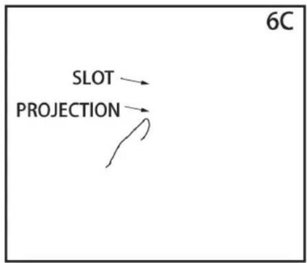
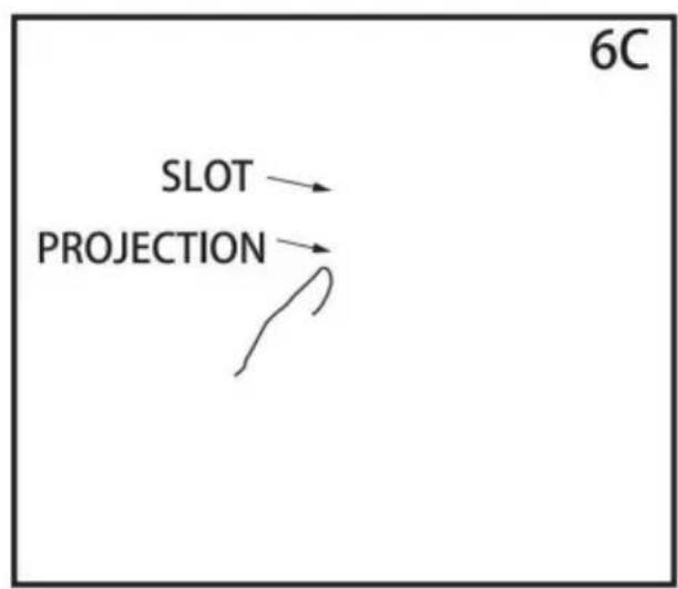
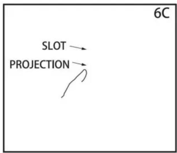
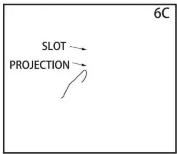
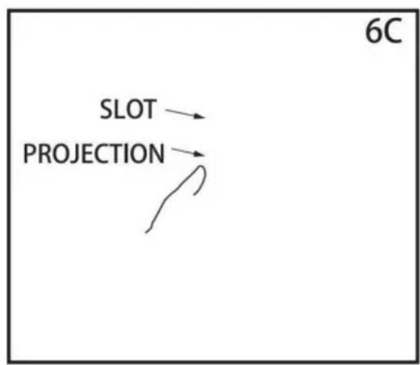
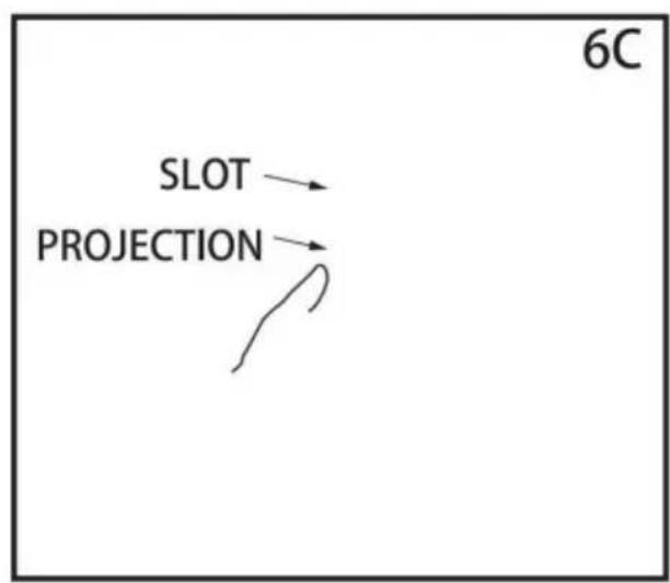
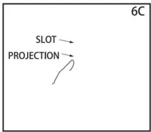
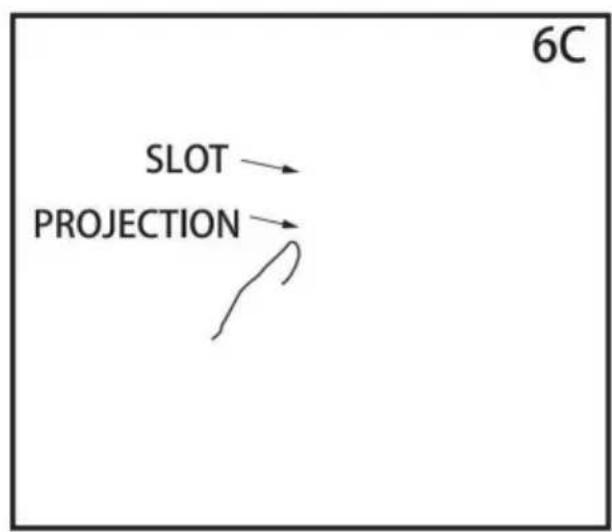
A. Line up disposer under mounting assembly. Guide hopper projections into mount ring slots. Turn mount ring about 1/4'to right so that disposer is temp
supported (see 6C).
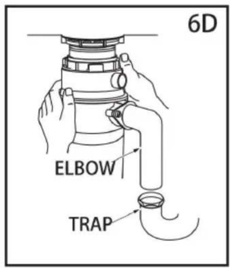
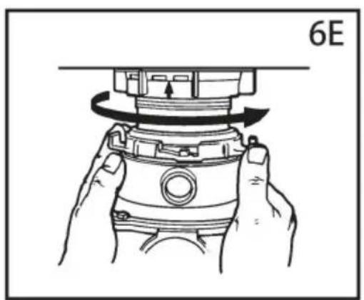
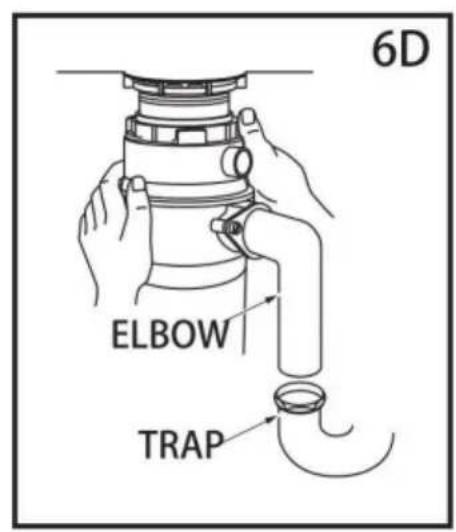
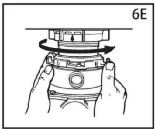
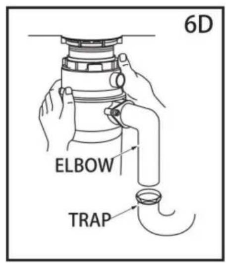
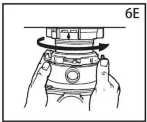
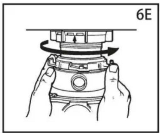
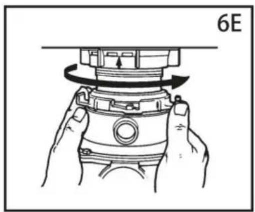
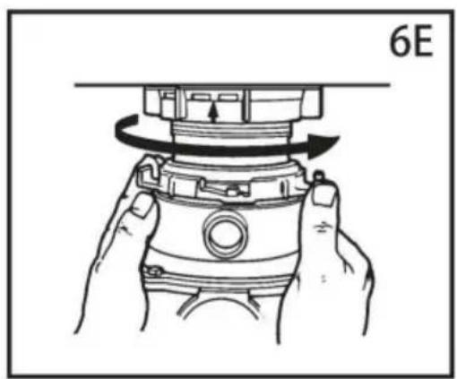
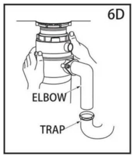
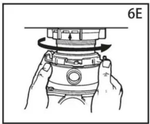
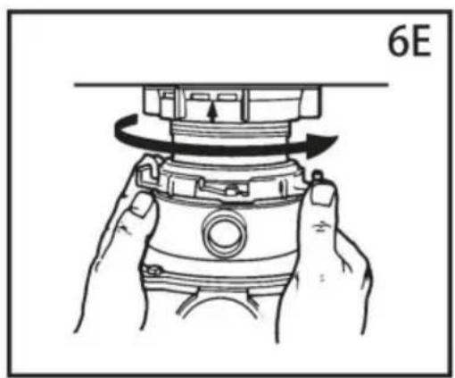
B. Turn mount ring and disposer until disposer elbow lines up with trap (see C. Turn mount ring to the right (counter-clockwise) until it locks up tight. Tap mount ring ears with a hammer until the lock position is achieved. Hopper projections must be to extreme left of mounting slots (see 6E).
D. If mount ring is hard to turn, you may add a small amount of petroleum liquid soap to hopper projections. Run water and check for leaks.
natural_image
Diagram of a hand holding a pipe fitting with a valve assembly (no text or symbols)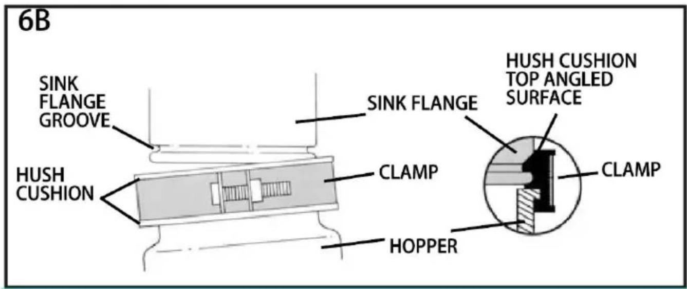
flowchart
graph TD
    A["SLOT"] --> B["PROJECTION"]
    B --> C["6C"]
natural_image
Illustration of hands assembling a mechanical component with a 6E label (no text or symbols on the diagram itself)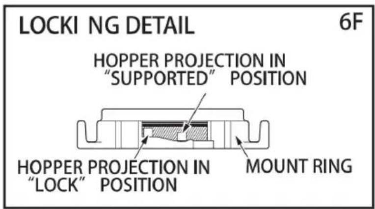
7. OPERATING INSTRUCTIONS
The Anti-Jam Swivel Impellers make a clicking sound as they swing into place is indicates normal operation.
A. Remove sink stopper. Turn on a medium flow of cold water.
B. Turn switch to ON position; your motor is turning at full speed and ready
C. Scrape in food waste. Down the drain go table scraps, peelings, rinds, se pits, small bones and coffee grounds. To speed up food waste disposal, cut break up large bones, rinds and cobs. Large bones and fibrous husks require considerable grinding time and are more easily thrown away with other trash. not be alarmed that the disposer slows down while grinding. The dis-poser is actually increasing torque (grinding power) and is operating under normal conditions.
D. Before turning disposer off, let water and disposer run for approximately 1 seconds after shredding stops. This assures that all waste is thoroughly flushed
through trap and drain.
A. Be sure disposer is empty before using your dishwasher so it may drain properly.
B. You may want to leave the stopper in the drain when not in use to pre utensils and foreign objects from falling into the disposer.
C. Your disposer is ruggedly built to give you many years of trouble free se will handle all normal food wastes, but it will NOT grind or dispose of such plastic, tin cans, bottle caps, glass, china, leather, cloth, rubber, string, clam and oyster shells, aluminum foil or feathers.
BATCH FEED OPERATING INSTRUCTIONS
The Anti-Jam Swivel Impellers make a clicking sound as they swing into place is indicates normal operation.
A. Remove sink stopper and turn on a medium flow of cold water.
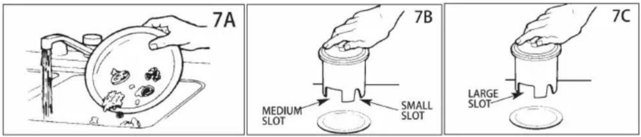
B. Scrape in food waste. Down the drain go table scraps, vegetable peelings rinds, pits, bones and coffee grounds.(see 7A)
C. Insert stopper to start disposer. (see 7B) One of the two small slots in a base must line up with switch plunger inside the neck of the disposer. Push firmly to turn the disposer on. Lift stopper to shut the disposer off.
D. Run disposer for 15 seconds after shredding stops. This assures that all is thoroughly flushed through the drain.
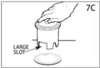
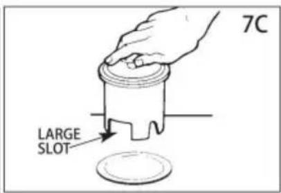
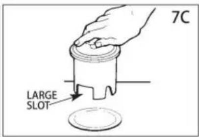
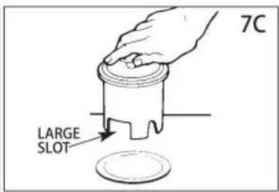
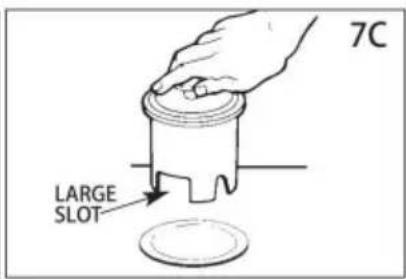
E. To fill sink, insert stopper and align the largest slot with the switch plung 7C)Push down to seal sink without starting the disposer. When medium sized (see 7B) in stopper base is lined up with the switch plunger, water can drain tableware, etc., cannot be accidentally dropped into disposer.
8. TROUBLESHOOTING
Before seeking repair or replacement, we recommend that you review the following.
LOUD NOISES: (Other than those during grinding of small bones and fruit pig) These are usually caused by accidental entry of a spoon, bottle cap or other foreign object. To correct this, turn off electrical switch and water. After disposed stopped, remove *splash guard, remove object with long handled tongs, and replace *splash guard.
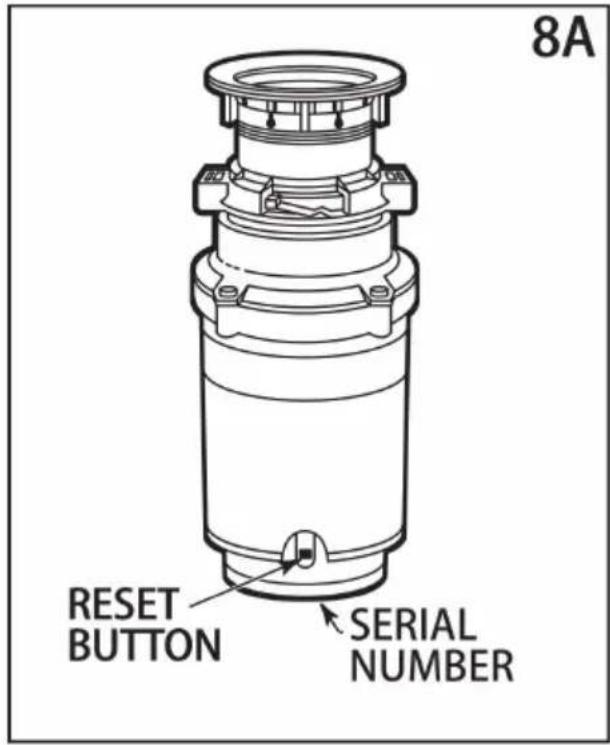
UNIT DOES NOT START: Unplug power cord or turn either the wall switch breaker box switch to "OFF" position, depending on your model and wiring configuration. Remove stopper and/or *splash guard. Check to see if turntable rotate freely using a wooden broom handle. If turntable rotates freely,
replace*splash guard and check re-set button to see if it has been tripped. F button is red and located opposite discharge elbow, near the bottom (see 8A Push button in until it clicks and remains depressed.
If re-set button has not been tripped, check for short-ed or broken wire conr to disposer. Check electrical power switch, fuse box or circuit breaker. If wirir electrical components are intact, the unit may have internal problems that req service or replacement.
* Splash guard not used on Top Control/Batch Feed unit.
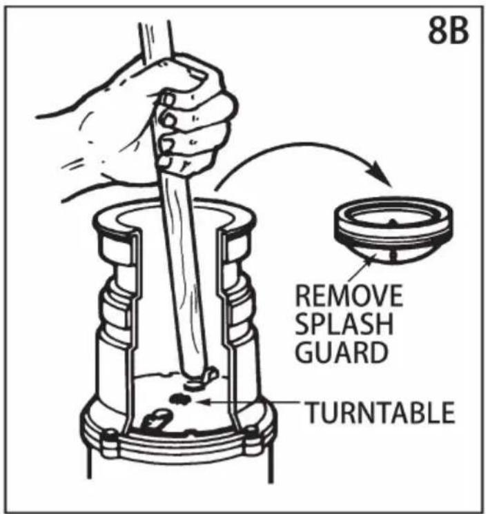
IF TURNTABLE DOES NOT ROTATE FREELY: Turn off disposer, then check any foreign object lodged between the turntable and grind ring. Dislodge object rotating table with a wooden broom handle and remove object. (see 8B) If no foreign object is present, there may be internal problems.
LEAKS: If the unit leaks at the top, it may be due to:
-
Improper seating of sink flange (gasket centering, putty or tightening).
-
Support ring not tightened properly.
-
Defective or improperly installed cushion mount. If unit leaks at the waste e leak may be due to improper tightening of elbow flange screws.
9. CLEANING AND MAINTENANCE
- To machine dry, put your product into a family washing machine and dry low heat below 40^ C . Ensure that the textile has enough room to tumble free blanket draws in during washing, while still damp gently stretch until it returns original size.
DO NOT ATTE M PTTO LUBRICATE YOUR DI SPOSER!
The motor is permanently lubricated. The disposer is self cleaning and scours internal parts with each use.
NEVER put lye or chemical drain cleaners into the dis-poser, as they cause serious corrosion of metal parts. If used, resulting damage can be easily detected and all warranties are void. Mineral deposits from your water can form on the stainless steel turntable, giving the appearance of rust. DO NOT BE ALARME the stainless steel turntables used will not corrode.
Product Specifications
| Model | Input | Rated power | Installation mode | Motor type |
| JW-301 | 120Vac/60Hz | 1/2HP | Torsion lock typ installation | DC motor |
| JW-301DCN | 220-240Vac, 50Hz 1HP | 1/2HP | Torsion lock typ installation | DC motor |
| JWM-331 | 120Vac/60Hz | 1/2HP | 3 bolt mounting | DC motor |
| JWM-331DCN | 220-240Vac, 50Hz 1HP | 1/2HP | 3 bolt mounting | DC motor |
| JWM-V50 | 120Vac/60Hz | 3/4HP | 3 bolt mounting | DC motor |
| JWM-V50A | 220-240Vac, 50Hz 1HP | 3/4HP | 3 bolt mounting | DC motor |
| JW-V50 | 120Vac/60Hz | 3/4HP | Torsion lock typ installation | DC motor |
| JW-V50A | 220-240Vac, 50Hz 1HP | 3/4HP | 3 bolt mounting | DC motor |
| JW-731 | 120Vac/60Hz | 1HP | Torsion lock typ installation | DC motor |
| JW-731DCN | 220-240Vac, 50Hz 1HP | 1HP | 3 bolt mounting | DC motor |
| JWM-931 | 120Vac/60Hz | 1.25HP | Torsion lock typ installation | DC motor |
| JWM-931DCN | 220-240Vac, 50Hz 1HP | 1.25HP | 3 bolt mounting | DC motor |
VEVOR®
TOUGH TOOLS, HALF PRICE
Technical Support and E-Warranty Certificate
www.vevor.com/support
VEVOR®
TOUGH TOOLS, HALF PRICE
/JW-731/JW-731DCN/JWM-931/JWM-931DCN
natural_image
Close-up of a black cylindrical mechanical component with metallic top and mounting holes (no visible text or symbols)
natural_image
Close-up of a black cylindrical mechanical component with metallic top and central hub (no visible text or symbols)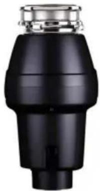
natural_image
Close-up of a black industrial component with metallic top and cylindrical body (no visible text or symbols)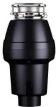
natural_image
Black industrial component with metallic top and stepped shaft (no visible text or symbols)JWM-331 JWM-331DCNJW-301DCNJV
natural_image
Close-up of a black mechanical component with metallic top and cylindrical body (no visible text or symbols)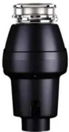
natural_image
Close-up of a black industrial pipe fitting with metallic fittings (no visible text or symbols)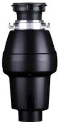
natural_image
Black mechanical component with a cylindrical body and flange (no visible text or symbols)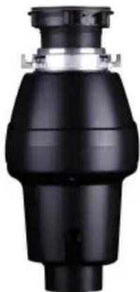
natural_image
Black industrial valve component with no visible text or symbolsJWM-V50 JWM-V50A JW-V50
JW-V50A
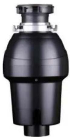
natural_image
Close-up of a black industrial valve or pump component with a cylindrical inlet (no visible text or symbols)JW-731
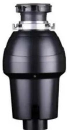
natural_image
Black industrial pipe fitting with a cylindrical top and flange (no visible text or symbols)JW-731DCN JWM-931 JWM-931DCN
natural_image
Black industrial component with metallic top and tapered body (no visible text or symbols)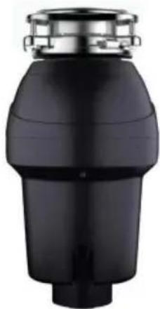
natural_image
Black cylindrical mechanical component with metallic top and stepped base (no visible text or symbols)BESOIN D'AIDE? CONTACTEZ-NOUS!
www.vevor.com/support
natural_image
Line drawing of a screwdriver with a flathead end (no text or symbols)PHILLIPS & FLATBLADE SCREWDRIVER
natural_image
Line drawing of a hand saw with a handle and blade (no text or symbols)HACKSAW
natural_image
Simple line drawing of a cylindrical object with a protruding port (no text or symbols)PLUMBER'S PUTTY
natural_image
Line drawing of three identical rectangular storage units with circular top caps, arranged horizontally (no text or symbols)DISHWASHER CONNECTOR KIT
natural_image
Line drawing of a hammer with textured handle and curved blade (no text or symbols)HAM M ER
natural_image
Line drawing of an adjustable wrench tool (no text or symbols present)PIPE WRENCH

DOW EL OR
STEEL PUNCH
natural_image
Black and white illustration of a coiled electrical plug with two terminal leads (no text or symbols)POWER CORD
STRAIN RELIEF
CONSIGNES DE SÉCURITÉ IMPORTANTES
INSTRUCTIONS RELATIVES AUX RISQUES D'INCENDIE, DE CHOC ÉLECTRIQUE OU RISQUE DE BLESSURES AUX PERSONNES. CONSERVEZ CES INSTRUCTIONS.
natural_image
Diagram of a hand connecting a U-shaped pipe with a wrench, labeled '1A' (no text or symbols on the diagram itself)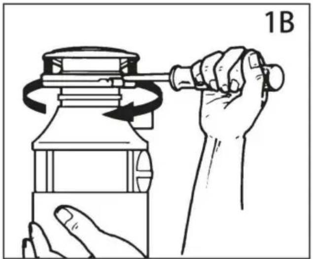
natural_image
Illustration of a hand using a tool to lift a mechanical component, showing rotational motion (no text or symbols)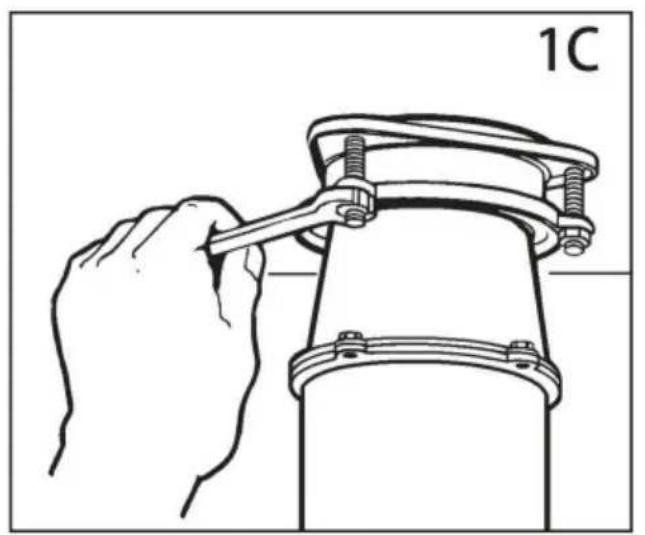
natural_image
Line drawing of a hand using a wrench to lift a mechanical component (no text or symbols)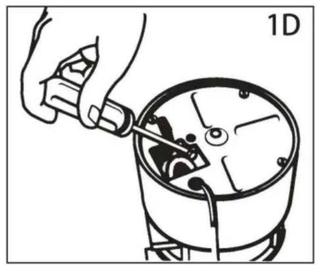
natural_image
Illustration of a hand using a tool to adjust or install a mechanical component, no text or symbols present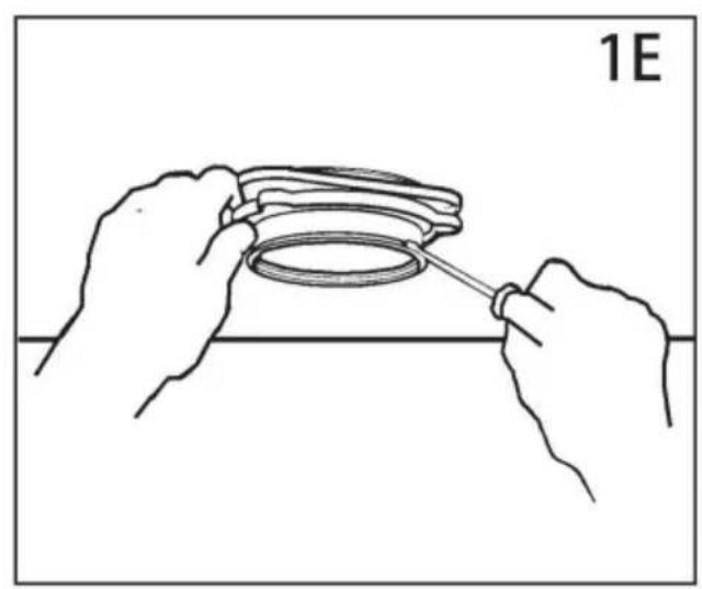
natural_image
Line drawing of hands holding a ring component with a tool, no text or symbols present2. RACCORDEMENT LAVE-VAISSELLE
3. INSTALLATION DE L'ENSEMBLE DE MONTAGE
VOTRE ÉLIMINATEUR EST LIVRÉ AVEC L'UN DES SUPPORTS SUIVANTS SYSTÈMES
AVIS IMPORTANT : DÉTAIL DU SUPPORT DE COUSSIN
natural_image
Line drawing of hands assembling a mechanical component (no text or symbols)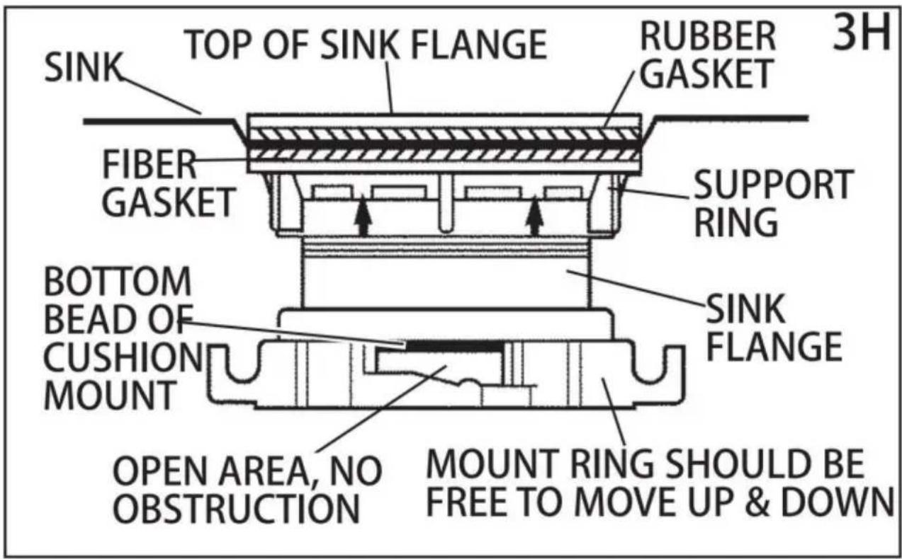
natural_image
Line drawing of a hand using a wrench to adjust a U-shaped pipe fitting (no text or symbols)6. RACCORDEMENT DU DISPOSITIF DE DÉCHET AU SUPPORT
Machine Translated by Google
natural_image
Diagram of a hand holding a pipe fitting with a valve assembly (no text or symbols)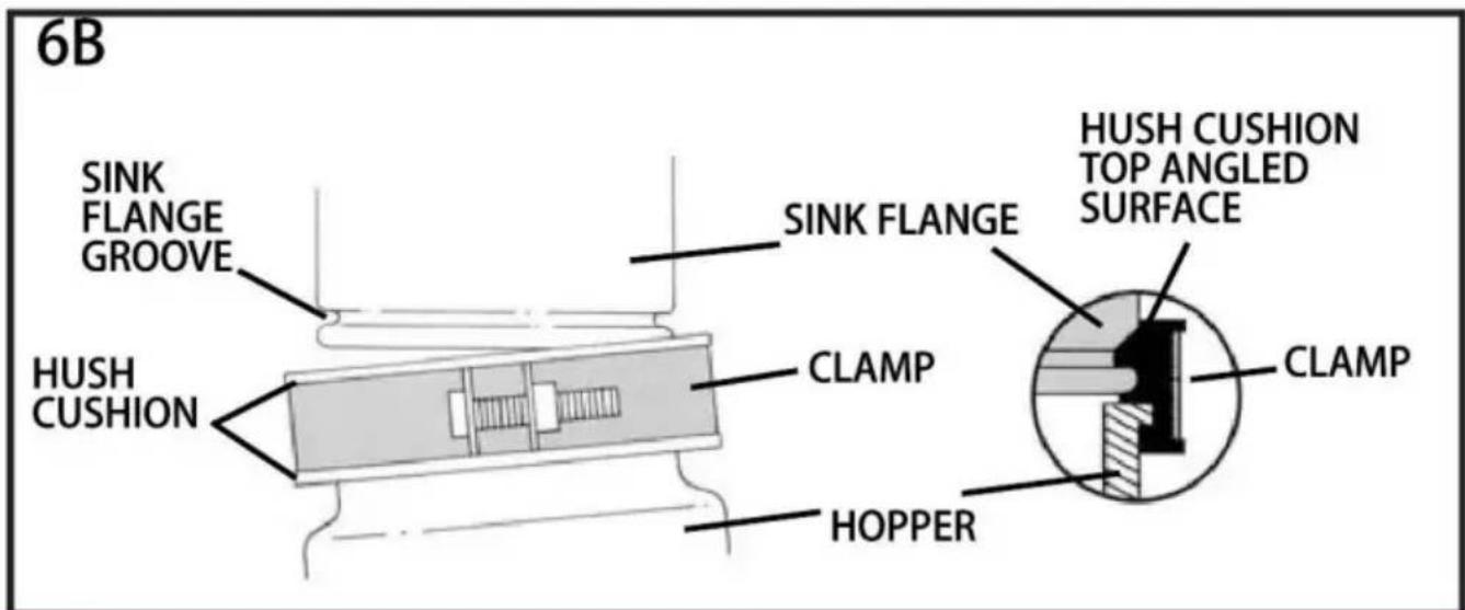
flowchart
graph TD
    A["SLOT"] --> B["PROJECTION"]
    B --> C["6C"]
natural_image
Illustration of hands assembling a mechanical component with a rotating arrow (no text or symbols)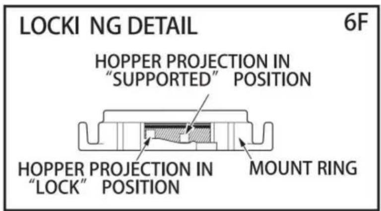
7. INSTRUCTIONS D'UTILISATION
natural_image
Illustration of a hand washing a petri dish with granular contents, placed on a surface (no text or symbols)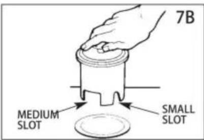
8. DÉPANNAGE
natural_image
Close-up of a black cylindrical mechanical component with metallic top and mounting holes (no visible text or symbols)
natural_image
Close-up of a black cylindrical mechanical component with metallic top and central hub (no visible text or symbols)
natural_image
Black industrial pipe fitting with metallic top (no visible text or symbols)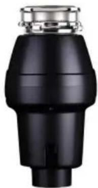
natural_image
Black industrial component with metallic top and stepped shaft (no visible text or symbols)JWM-331 JWM-331DCNJW-301DCNJV
natural_image
Close-up of a black mechanical component with metallic top and cylindrical body (no visible text or symbols)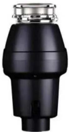
natural_image
Close-up of a black industrial pipe fitting with metallic fittings (no visible text or symbols)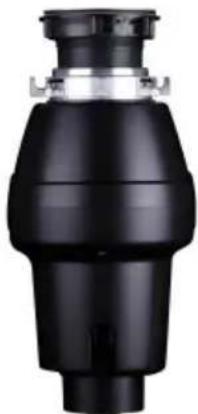
natural_image
Black industrial component with a cylindrical top and flanged side (no visible text or symbols)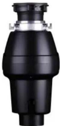
natural_image
Black industrial valve component with no visible text or symbolsJWM-V50 JWM-V50A JW-V50 JW-V50A
natural_image
Close-up of a black industrial valve or filter component with a metallic top and side outlet (no visible text or symbols)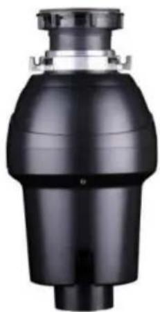
natural_image
Close-up of a black industrial valve or pump component with a cylindrical inlet (no visible text or symbols)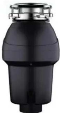
natural_image
Black industrial pipe fitting with a metallic top (no text or symbols visible)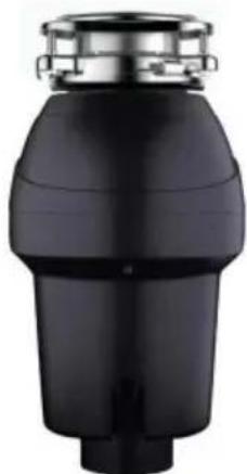
natural_image
Black cylindrical mechanical component with a metallic top and flange (no visible text or symbols)JWM-931 JWM-931DCNJW-731 JW-
www.vevor.com/support
natural_image
Line drawing of a screwdriver with a flathead end (no text or symbols)PHILLIPS & FLATBLADE SCREWDRIVER
natural_image
Line drawing of a hand using a saw (no text or symbols)HACKSAW
natural_image
Simple line drawing of a cylindrical object with a protruding handle (no text or symbols)PLUMBER'S PUTTY
natural_image
Line drawing of three identical rectangular storage units with circular top caps, arranged horizontally (no text or symbols)DISHWASHER CONNECTOR KIT
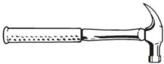
natural_image
Line drawing of a hammer with textured handle and pointed tip (no text or symbols)HAMMER
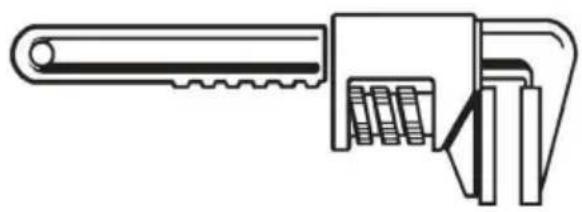
natural_image
Line drawing of an adjustable wrench with a handle and spring (no text or symbols)PIPE WRENCH

DOW EL OR
STEEL PUNCH
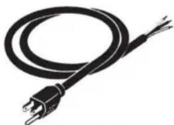
natural_image
Black and white illustration of a coiled electrical plug with two terminal leads (no text or symbols)POWER CORD
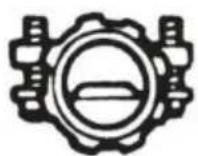
STRAIN RELIEF
Machine Translated by Google
natural_image
Diagram of a hand connecting a U-shaped pipe with a wrench, labeled '1A' (no text or symbols on the diagram itself)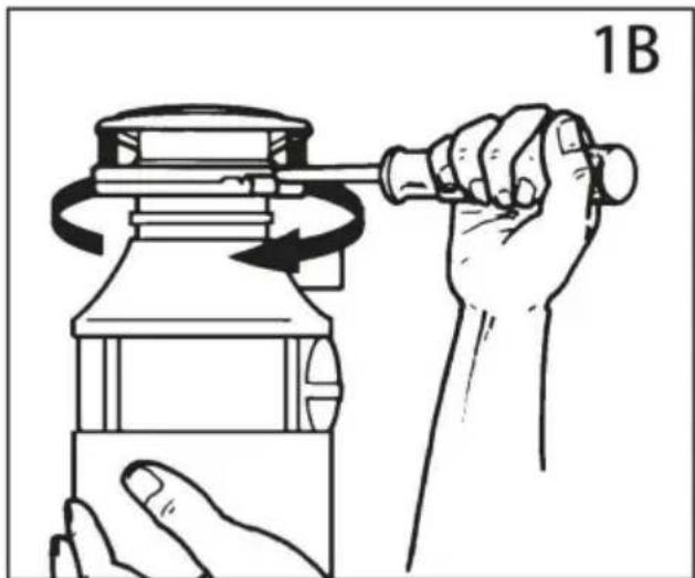
natural_image
Illustration of a hand using a tool to lift a cylindrical object, showing rotational motion (no text or symbols)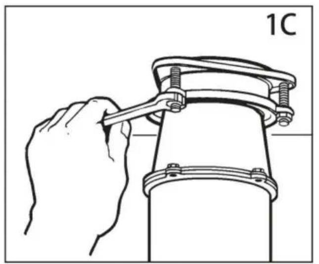
natural_image
Line drawing of a hand using a wrench to lift a mechanical component (no text or symbols)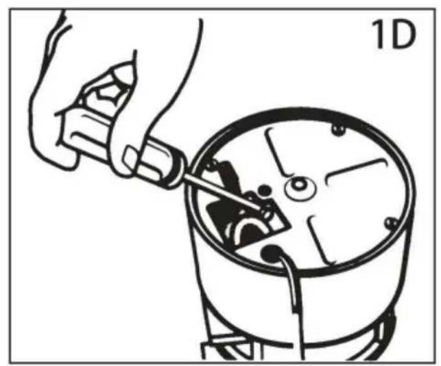
natural_image
Illustration of a hand using a tool to adjust or install a mechanical component, no text or symbols present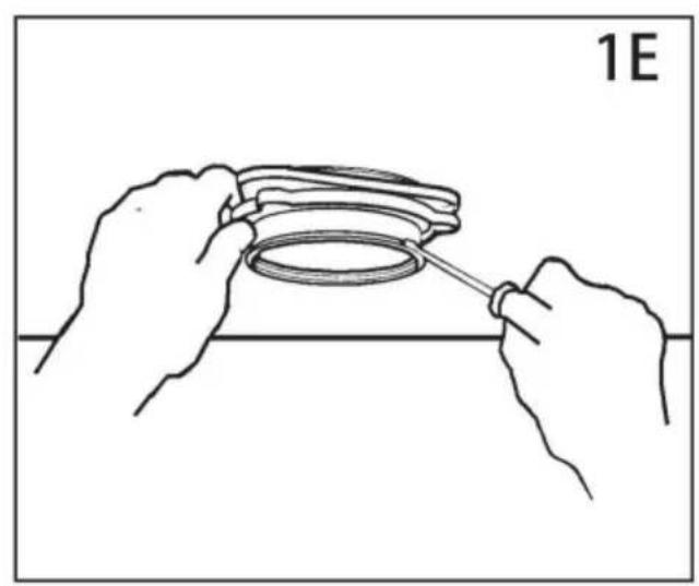
natural_image
Line drawing of hands holding a ring component with a tool, no text or symbols present3. MONTAGE DER MONTAGEBAUGRUPPE
natural_image
Line drawing of two hands holding a circular object with a magnified inset showing internal features (no text or symbols)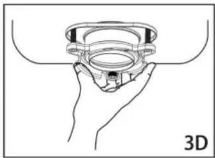
natural_image
Line drawing of a hand holding a 3D mechanical component (no text or symbols)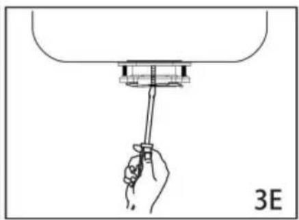
natural_image
Hand holding a tool above a mechanical component, labeled '3E' (no text or symbols on the diagram itself)EZ-Montagesystem
VOR DEM START VOLLSTÄNDIG LESEN
natural_image
Illustration of hands assembling a mechanical component labeled '3G' (no text or symbols on the diagram itself)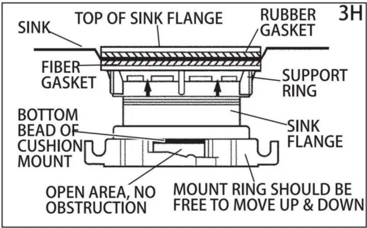
natural_image
Line drawing of a hand using a wrench to adjust a U-shaped pipe fitting (no text or symbols)natural_image
Diagram of a hand holding a pipe fitting with a valve assembly (no text or symbols)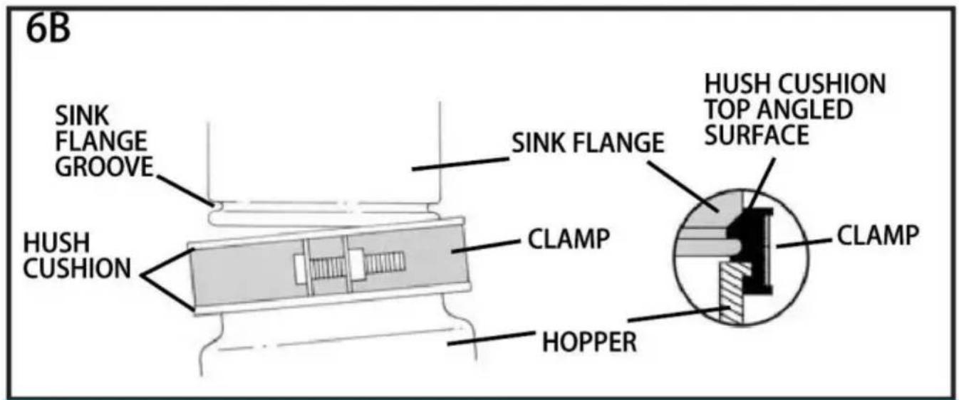
flowchart
graph TD
    A["SLOT"] --> B["PROJECTION"]
    B --> C["6C"]
natural_image
Illustration of hands assembling a mechanical component with a rotating arrow (no text or symbols)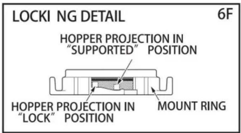
natural_image
Illustration of a hand washing a dish with granular contents, no text or symbols present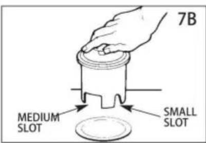
8. FEHLERSUCHE
www.vevor.com/support
VEVOR®
TOUGH TOOLS, HALF PRICE
natural_image
Close-up of a black cylindrical mechanical component with metallic top and mounting holes (no visible text or symbols)
natural_image
Black cylindrical mechanical component with metallic top and mounting holes (no visible text or symbols)
natural_image
Black industrial pipe fitting with metallic top (no visible text or symbols)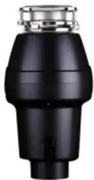
natural_image
Black industrial component with metallic top and stepped shaft (no visible text or symbols)JWM-331DCN
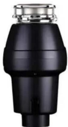
Modello JW-301DCNCodice JW-30WM-331
natural_image
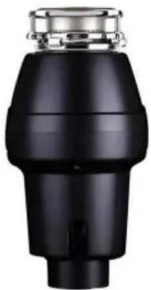
Close-up of a black industrial component with metallic top and cylindrical body (no visible text or symbols)Modello JWM-V50
natural_image
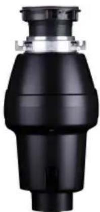
Close-up of a black industrial pipe fitting with metallic fittings (no visible text or symbols)JWM-V50A
natural_image
Black mechanical component with cylindrical body and flange (no visible text or symbols)Modello JW-V50
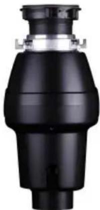
natural_image
Black industrial valve component with no visible text or symbolsModello JW-V50A
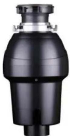
natural_image
Close-up of a black industrial valve or pump component with a cylindrical body and flange (no visible text or symbols)Codice JW-731
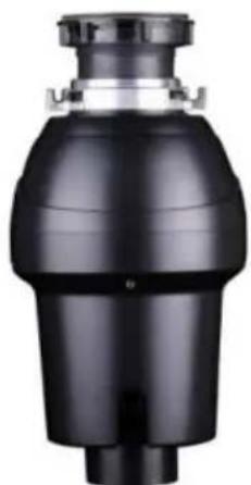
natural_image
Black industrial pipe fitting with a cylindrical top and flange (no visible text or symbols)Modello JW-731DCN JWM-931JWM-931DCN
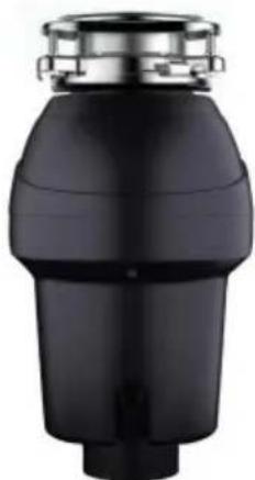
natural_image
Black cylindrical mechanical component with a metallic top (no visible text or symbols)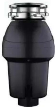
natural_image
Black cylindrical mechanical component with metallic top and stepped base (no visible text or symbols)www.vevor.com/support
natural_image
Line drawing of a screwdriver with a flathead end (no text or symbols)PHILLIPS & FLATBLADE SCREWDRIVER
natural_image
Line drawing of a hand saw with a handle and blade (no text or symbols)HACKSAW
natural_image
Simple line drawing of a cylindrical object with a protruding port (no text or symbols)PLUMBER'S PUTTY
natural_image
Line drawing of three identical rectangular storage units with circular top caps, arranged horizontally (no text or symbols)DISHWASHER CONNECTOR KIT
natural_image
Line drawing of a hammer with textured handle and curved blade (no text or symbols)HAM M ER
natural_image
Line drawing of an adjustable wrench tool (no text or symbols present)PIPE WRENCH

DOW EL OR
STEEL PUNCH
natural_image
Black and white illustration of a coiled electrical plug with two terminal leads (no text or symbols)POWER CORD
STRAIN RELIEF
IMPORTANTI ISTRUZIONI DI SICUREZZA
ISTRUZIONI RELATIVE AL RISCHIO DI INCENDIO, SCOSSE ELETTRICHE O
INFORTUNIO PERSONE. CONSERVARE QUESTE ISTRUZIONI.
natural_image
Diagram of a hand connecting a U-shaped pipe with a wrench, labeled '1A' (no text or symbols on the diagram itself)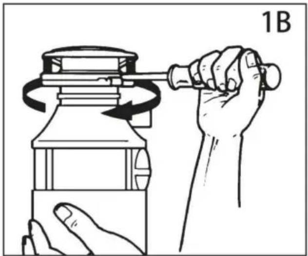
natural_image
Illustration of a hand using a tool to lift a cylindrical object, showing rotational motion (no text or symbols)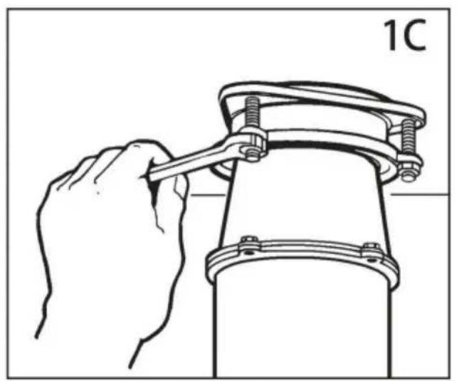
natural_image
Line drawing of a hand using a wrench to lift a mechanical component (no text or symbols)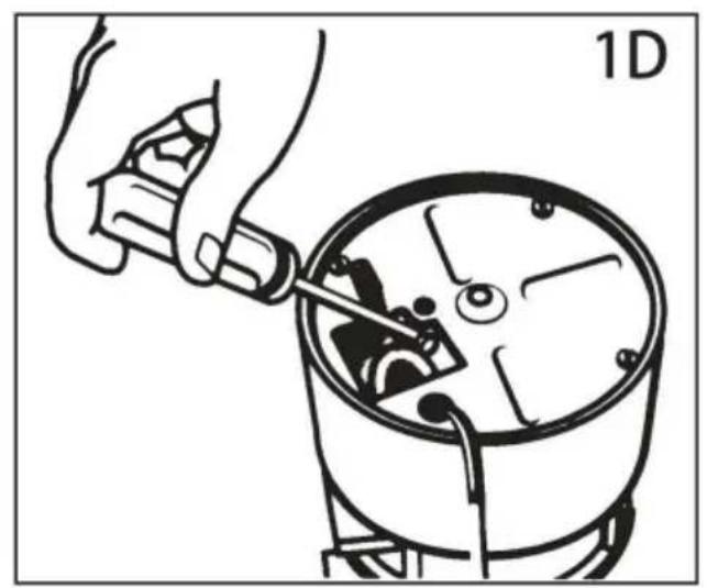
natural_image
Illustration of a hand using a tool to adjust or install a mechanical component, no text or symbols present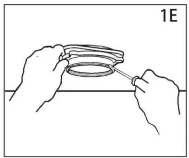
natural_image
Line drawing of hands assembling a circular component with a tool, labeled '1E' (no text or symbols on the diagram itself)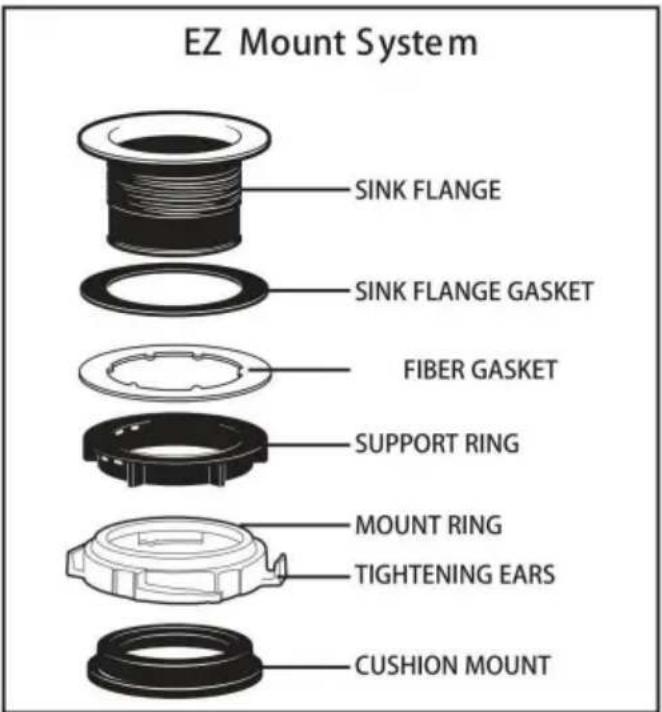
AVVISO IMPORTANTE: DETTAGLIO DEL MONTAGGIO DEL CUSCINO
natural_image
Illustration of hands assembling a mechanical component labeled '3G' (no text or symbols on the diagram itself)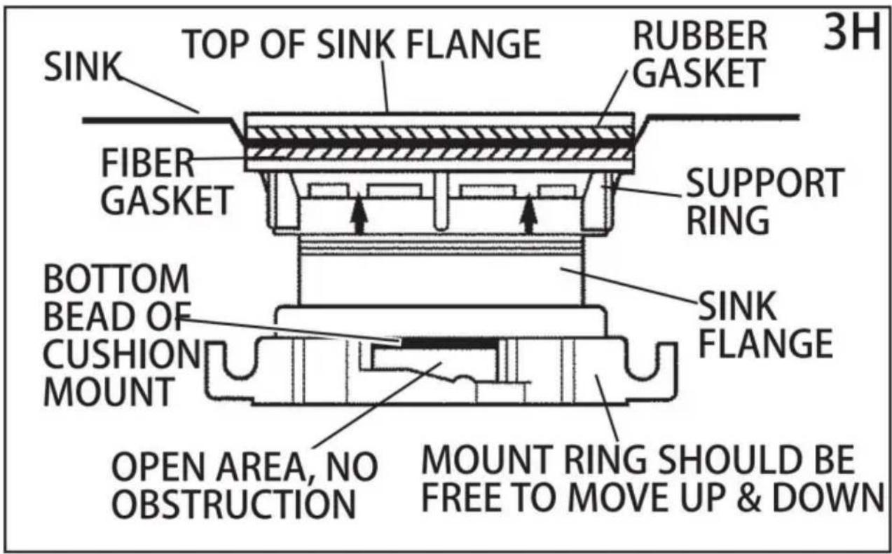
4. COLLEGAMENTI ELETTRICI
natural_image
Line drawing of a hand using a wrench to adjust a U-shaped pipe fitting (no text or symbols)6. COLLEGAMENTO DEL DISPOSITIVO AL GRUPPO DI MONTAGGIO
natural_image
Diagram of a hand holding a pipe fitting with a valve assembly (no text or symbols)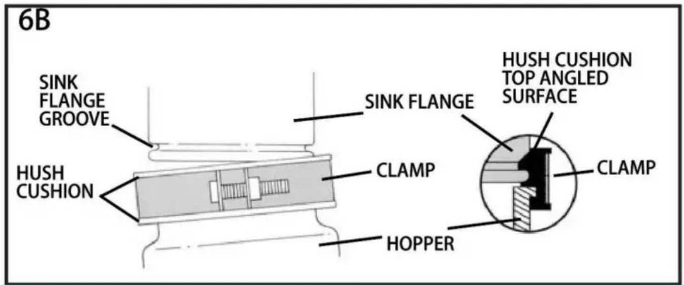
flowchart
graph TD
    A["SLOT"] --> B["PROJECTION"]
    B --> C["6C"]
natural_image
Illustration of hands assembling a mechanical component with a rotating arrow (no text or symbols)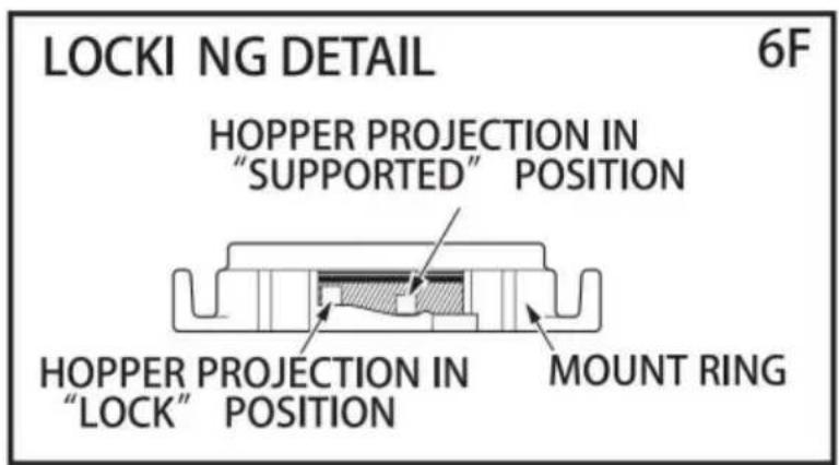
7. ISTRUZIONI PER L'USO
natural_image
Illustration of a hand washing a dish with granular contents, no text or symbols present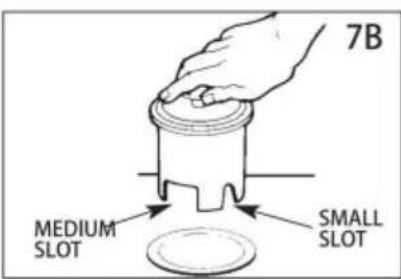
8. RISOLUZIONE DEI PROBLEMI
/JW-731/JW-731DCN/JWM-931/JWM-931DCN
natural_image
Close-up of a black cylindrical mechanical component with metallic top and mounting holes (no visible text or symbols)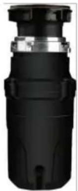
natural_image
Close-up of a black cylindrical mechanical component with metallic fittings and a small outlet (no visible text or symbols)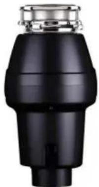
natural_image
Black industrial pipe fitting with metallic top (no visible text or symbols)
natural_image
Black industrial component with metallic top and stepped shaft (no visible text or symbols)JW-301DCN JWM-331DCNJWM-331JW-301
natural_image
Close-up of a black industrial component with metallic top and cylindrical body (no visible text or symbols)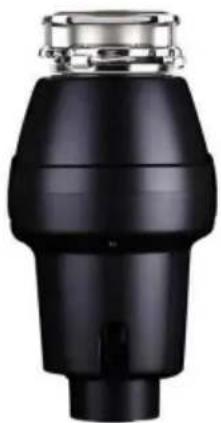
natural_image
Close-up of a black industrial pipe fitting with metallic fittings (no visible text or symbols)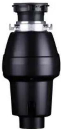
natural_image
Black mechanical component with a cylindrical body and flange (no visible text or symbols)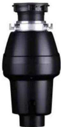
natural_image
Black industrial valve component with no visible text or symbolsJWM-V50AJWM-V50 JW-V50
JW-V50A
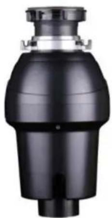
natural_image
Close-up of a black industrial valve or pump component with a cylindrical inlet (no visible text or symbols)JW-731
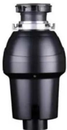
natural_image
Black cylindrical mechanical component with a flanged top and central shaft (no visible text or symbols)JW-731DCN JWM-931 JWM-931DCN
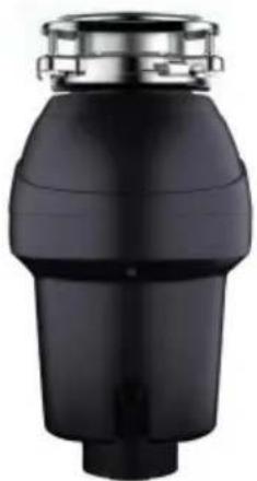
natural_image
Black industrial component with metallic top and tapered body (no visible text or symbols)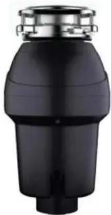
natural_image
Black cylindrical mechanical component with metallic top and stepped base (no visible text or symbols)www.vevor.com/support
natural_image
Line drawing of a screwdriver with a flathead end (no text or symbols)PHILLIPS & FLATBLADE SCREWDRIVER
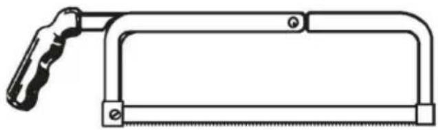
natural_image
Line drawing of a hand saw with a handle and blade (no text or symbols)HACKSAW
natural_image
Simple line drawing of a cylindrical object with a protruding knob (no text or symbols)PLUMBER'S PUTTY
natural_image
Line drawing of three identical rectangular storage units with circular top caps, arranged horizontally (no text or symbols)DISHWASHER CONNECTOR KIT
natural_image
Line drawing of a hammer with textured handle and curved blade (no text or symbols)HAM M ER
natural_image
Line drawing of an adjustable wrench tool (no text or symbols present)PIPE WRENCH

DOW EL OR
STEEL PUNCH
natural_image
Black and white illustration of a coiled electrical plug with two terminal leads (no text or symbols)POWER CORD
STRAIN RELIEF
natural_image
Diagram of a hand connecting a U-shaped pipe with a wrench, labeled '1A' (no text or symbols on the diagram itself)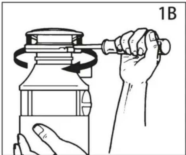
natural_image
Illustration of a hand using a tool to lift a cylindrical object, showing rotational motion (no text or symbols)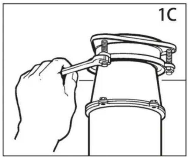
natural_image
Line drawing of a hand using a wrench to lift a mechanical component (no text or symbols)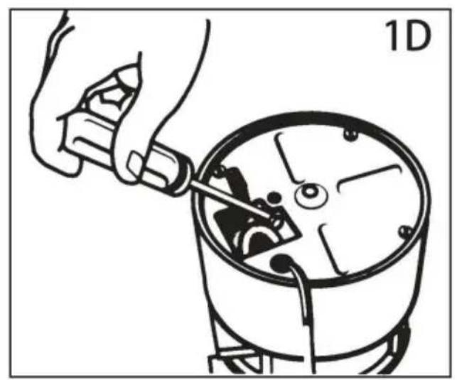
natural_image
Illustration of a hand using a tool to adjust or install a mechanical component, no text or symbols present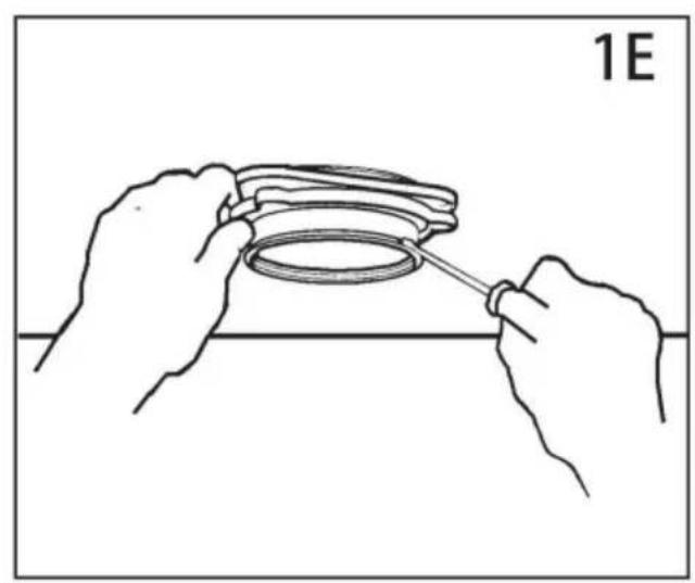
natural_image
Line drawing of hands holding a ring component with a tool, no text or symbols present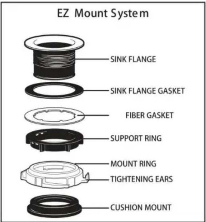
AVISO IMPORTANTE: DETALLE DEL SOPORTE DEL COJÍN
natural_image
Illustration of hands assembling a mechanical component labeled '3G' (no text or symbols on the diagram itself)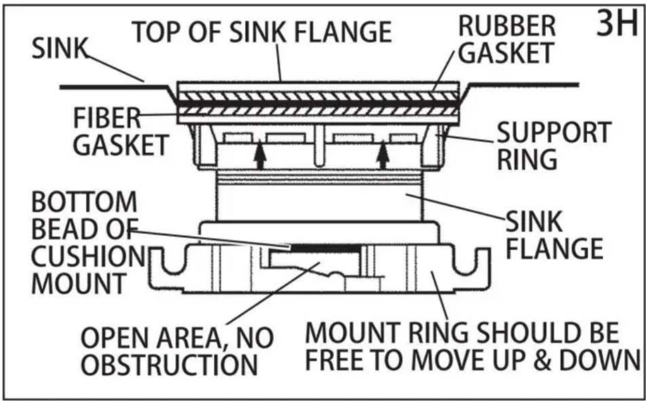
4. CONEXIONES ELÉCTRICAS

natural_image
Line drawing of a hand using a wrench to adjust a U-shaped pipe fitting (no text or symbols)natural_image
Diagram of a hand holding a pipe fitting with a valve assembly (no text or symbols)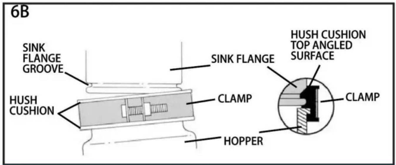
flowchart
graph TD
    A["SLOT"] --> B["PROJECTION"]
    B --> C["6C"]
natural_image
Illustration of hands assembling a mechanical component with a rotating arrow (no text or symbols)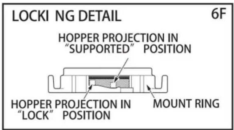
7. INSTRUCCIONES DE USO
natural_image
Illustration of a hand washing a dish with granular contents, no text or symbols present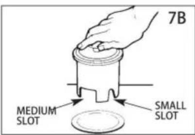
/JW-731/JW-731DCN/JWM-931/JWM-931DCN
natural_image
Close-up of a black cylindrical mechanical component with metallic top and mounting holes (no visible text or symbols)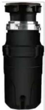
natural_image
Close-up of a black cylindrical mechanical component with metallic top and central hub (no visible text or symbols)
natural_image
Black industrial pipe fitting with metallic top (no visible text or symbols)
natural_image
Black industrial component with metallic top and stepped shaft (no visible text or symbols)JWM-331 JWM-331DCNJW-301DCNJW-301
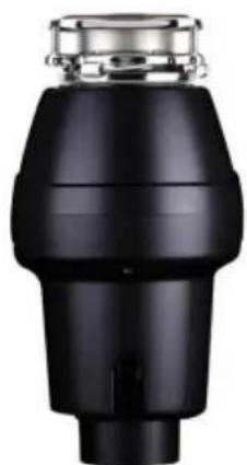
natural_image
Close-up of a black industrial component with metallic top and cylindrical body (no visible text or symbols)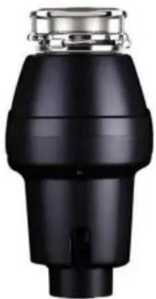
natural_image
Close-up of a black industrial pipe fitting with metallic fittings (no visible text or symbols)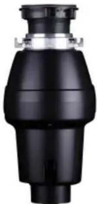
natural_image
Black mechanical component with a cylindrical body and flange (no visible text or symbols)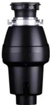
natural_image
Black industrial valve component with no visible text or symbolsJWM-V50 JWM-V50A JW-V50 JW-V50A
natural_image
Close-up of a black industrial valve or pump component with a cylindrical inlet (no visible text or symbols)
natural_image
Black industrial pipe fitting with a cylindrical top and flange (no visible text or symbols)
natural_image
Black industrial component with metallic top and tapered body (no visible text or symbols)
natural_image
Black cylindrical mechanical component with metallic top and stepped base (no visible text or symbols)JW-731DCNJW-731 JWM-931 JWM-931DCN
POTRZEBUJESZ POMOCY? SKONTAKTUJ SIĘ Z NAMI!
natural_image
Line drawing of a screwdriver with a flathead end (no text or symbols)PHILLIPS & FLATBLADE SCREWDRIVER
natural_image
Line drawing of a hand using a saw (no text or symbols)HACKSAW
natural_image
Simple line drawing of a cylindrical object with a protruding knob (no text or symbols)PLUMBER'S PUTTY
natural_image
Line drawing of three identical rectangular storage units with circular top caps, arranged horizontally (no text or symbols)DISHWASHER CONNECTOR KIT
natural_image
Line drawing of a hammer with textured handle and pointed tip (no text or symbols)HAMMER
natural_image
Line drawing of an adjustable wrench tool (no text or symbols)PIPE WRENCH

DOW EL OR
STEEL PUNCH
natural_image
Black and white illustration of a coiled electrical plug with two terminal leads (no text or symbols)POWER CORD
STRAIN RELIEF
WAŻNE INSTRUKCJE BEZPIECZEŃSTWA
INSTRUKCJE DOTYCZĄCE RYZYKA POŻARU, PORAŻENIA PRĄDEM ELEKTRYCZNYM LUB OSOBY, KTÓRE DOZNAŁY URAZU. ZACHOWAJ TE INSTRUKCJE.
natural_image
Diagram of a hand connecting a U-shaped pipe with a wrench, labeled '1A' (no text or symbols on the diagram itself)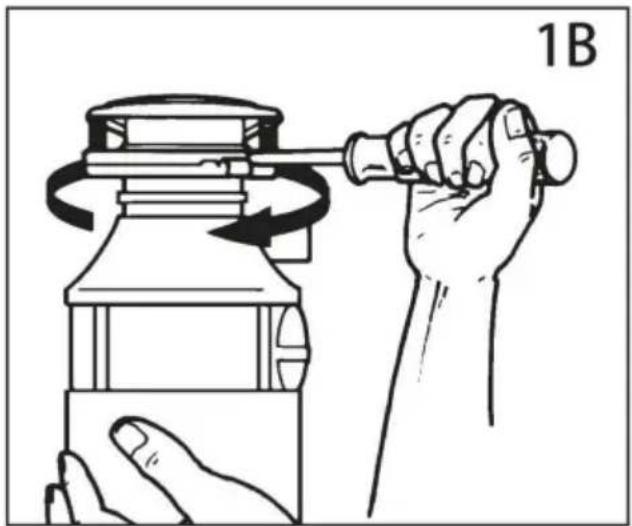
natural_image
Line drawing of a hand using a tool to lift a bottle, showing motion and rotation (no text or symbols)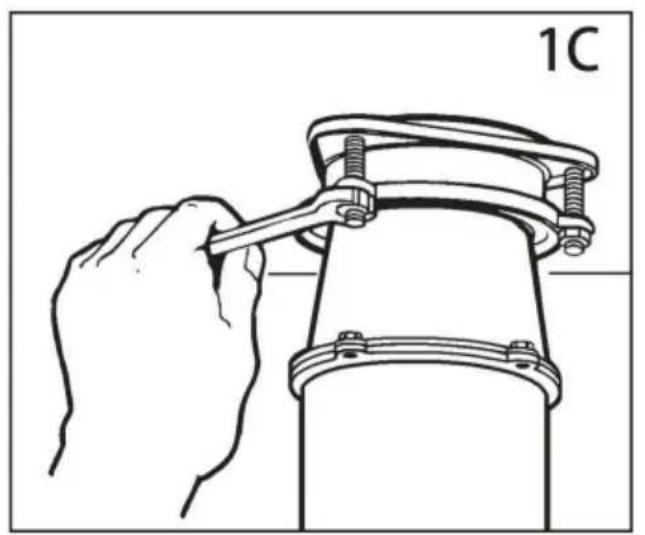
natural_image
Line drawing of a hand using a wrench to lift a mechanical component (no text or symbols)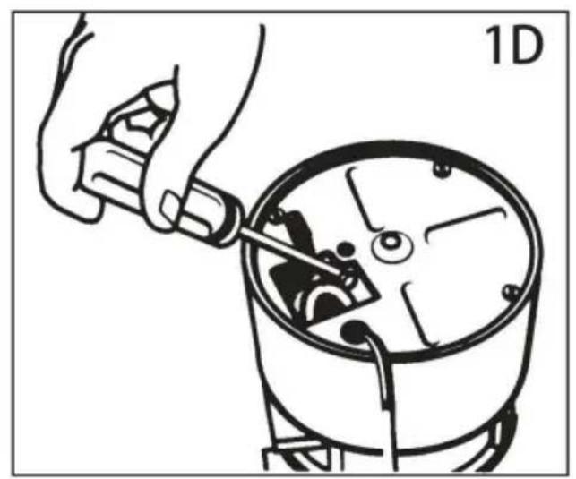
natural_image
Illustration of a hand using a tool to adjust or install a mechanical component, no text or symbols present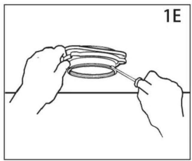
natural_image
Line drawing of hands holding a ring component with a tool, no text or symbols present2. PODŁĄCZENIE ZMYWARKI
3. MONTAŻ ZESTAWU MONTAŻOWEGO
TWOJE URZĄDZENIE DOSTARCZANE JEST Z JEDNYM Z NASTĘPUJĄCYCH MOCOWAŃ SYSTEMY
WAŻNA INFORMACJA: SZCZEGÓŁY MOCOWANIA PODUSZKI
natural_image
Illustration of hands assembling a mechanical component labeled '3G' (no text or symbols on the diagram itself)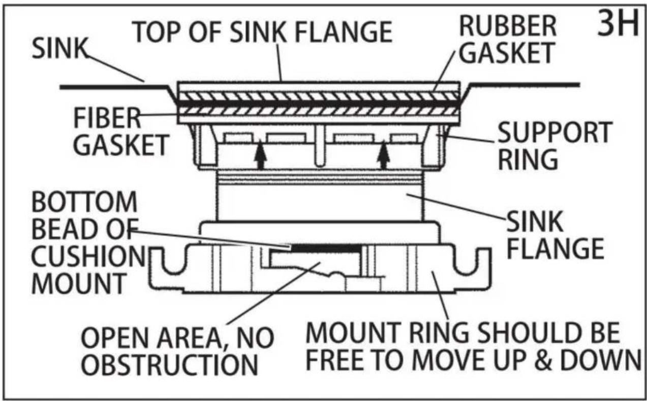
natural_image
Line drawing of a hand using a wrench to adjust a U-shaped pipe fitting (no text or symbols)6. PODŁĄCZANIE ROZDRABNIACZA DO ZESTAWU MONTAŻOWEGO
Machine Translated by Google
natural_image
Diagram of a hand holding a pipe fitting with a valve assembly (no text or symbols)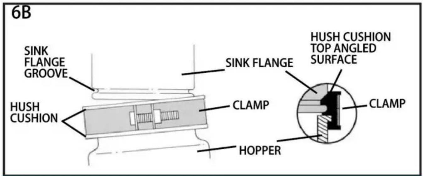
flowchart
graph TD
    A["SLOT"] --> B["PROJECTION"]
    B --> C["6C"]
natural_image
Illustration of hands assembling a mechanical component with a rotating arrow (no text or symbols)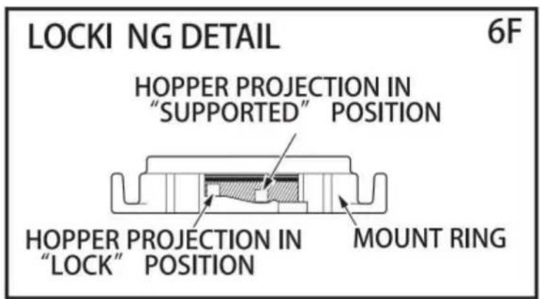
7. INSTRUKCJA OBSŁUGI
natural_image
Close-up of a black cylindrical mechanical component with metallic top and mounting holes (no visible text or symbols)
natural_image
Close-up of a black cylindrical mechanical component with metallic top and central hub (no visible text or symbols)
natural_image
Black industrial pipe fitting with metallic top (no visible text or symbols)
natural_image
Black industrial component with metallic top and stepped shaft (no visible text or symbols)JWM-331 JWM-331DCNJW-301DCNJV
natural_image
Close-up of a black industrial component with metallic top and cylindrical body (no visible text or symbols)
natural_image
Close-up of a black industrial pipe fitting with metallic fittings (no visible text or symbols)
natural_image
Black mechanical component with a cylindrical body and flange (no visible text or symbols)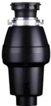
natural_image
Black industrial valve component with metallic fittings (no visible text or symbols)JWM-V50 JW-V50JWM-V50A JW-V50A
natural_image
Close-up of a black industrial valve or pump component with a metallic top and side outlet (no visible text or symbols)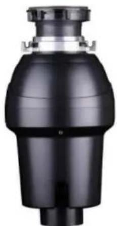
natural_image
Black cylindrical mechanical component with a flanged top and central shaft (no visible text or symbols)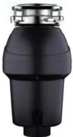
natural_image
Black cylindrical mechanical component with metallic top and stepped base (no visible text or symbols)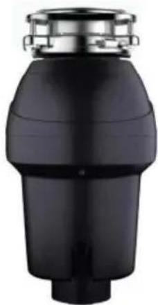
natural_image
Black cylindrical mechanical component with a metallic top and flange (no visible text or symbols)JW-731DCNJW-731 JWM-931 JWM-931DCN
HULP NODIG? NEEM CONTACT MET ONS OP!
www.vevor.com/support
natural_image
Line drawing of a screwdriver with a flathead end (no text or symbols)PHILLIPS & FLATBLADE SCREWDRIVER
natural_image
Line drawing of a hand using a saw (no text or symbols)HACKSAW
natural_image
Simple line drawing of a cylindrical object with a protruding handle (no text or symbols)PLUMBER'S PUTTY
natural_image
Line drawing of three identical rectangular storage units with circular top caps, arranged horizontally (no text or symbols)DISHWASHER CONNECTOR KIT
natural_image
Line drawing of a hammer with textured handle and curved blade (no text or symbols)HAMMER
natural_image
Line drawing of an adjustable wrench tool (no text or symbols present)PIPE WRENCH

DOW EL OR
STEEL PUNCH
natural_image
Black and white illustration of a coiled electrical plug with two terminal leads (no text or symbols)POWER CORD

STRAIN RELIEF
BELANGRIJKE VEILIGHEIDSINSTRUCTIES
INSTRUCTIES MET BETREKKING TOT HET RISICO OP BRAND, ELEKTRISCHE SCHOK OF LETSEL TOPPERSONEN. BEWAAR DEZE INSTRUCTIES.
natural_image
Diagram of a hand connecting a U-shaped pipe with a wrench, labeled '1A' (no text or symbols on the diagram itself)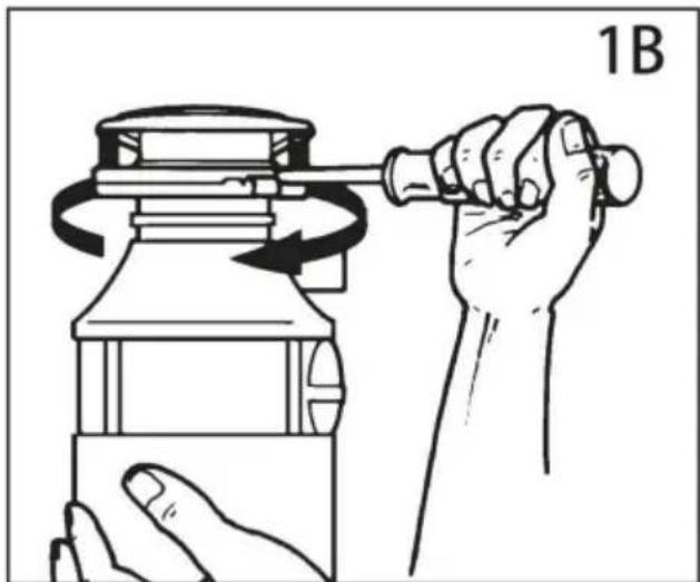
natural_image
Illustration of a hand using a tool to lift a cylindrical object, showing rotational motion (no text or symbols)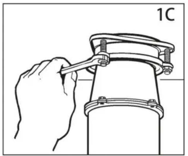
natural_image
Line drawing of a hand using a wrench to lift a mechanical clamp or bracket (no text or symbols)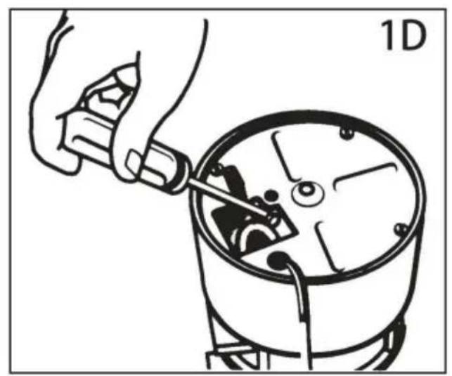
natural_image
Illustration of a hand using a tool to adjust or install a mechanical component, no text or symbols present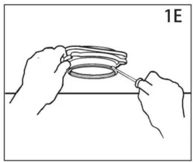
natural_image
Line drawing of hands holding a ring component with a tool, no text or symbols present2. AANSLUITING VAATWASSER
3. INSTALLATIE VAN DE MONTAGE-EENHEID
UW AFVALVERWERKER WORDT GELEVERD MET EEN VAN DE VOLGENDE BEVESTIGINGEN SYSTEMEN
natural_image
Line drawing of two hands holding a circular object with a magnified inset showing internal features (no text or symbols)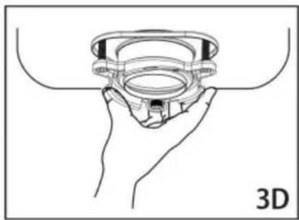
natural_image
Line drawing of a hand holding a 3D mechanical component (no text or symbols)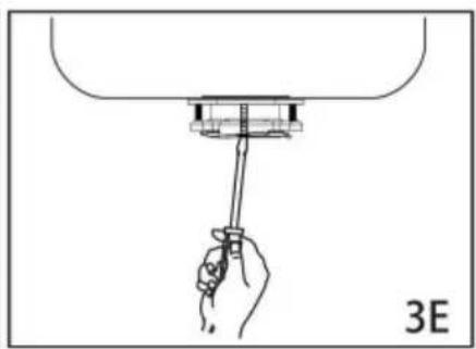
natural_image
Hand holding a tool above a mechanical component, labeled '3E' (no text or symbols on the diagram itself)EZ-montagesysteem
LEES HET VOLLEDIG DOOR VOORDAT U BEGINT
BELANGRIJKE OPMERKING: DETAIL VAN DE KUSSENMONTAGE
natural_image
Illustration of hands assembling a mechanical component labeled '3G' (no text or symbols on the diagram itself)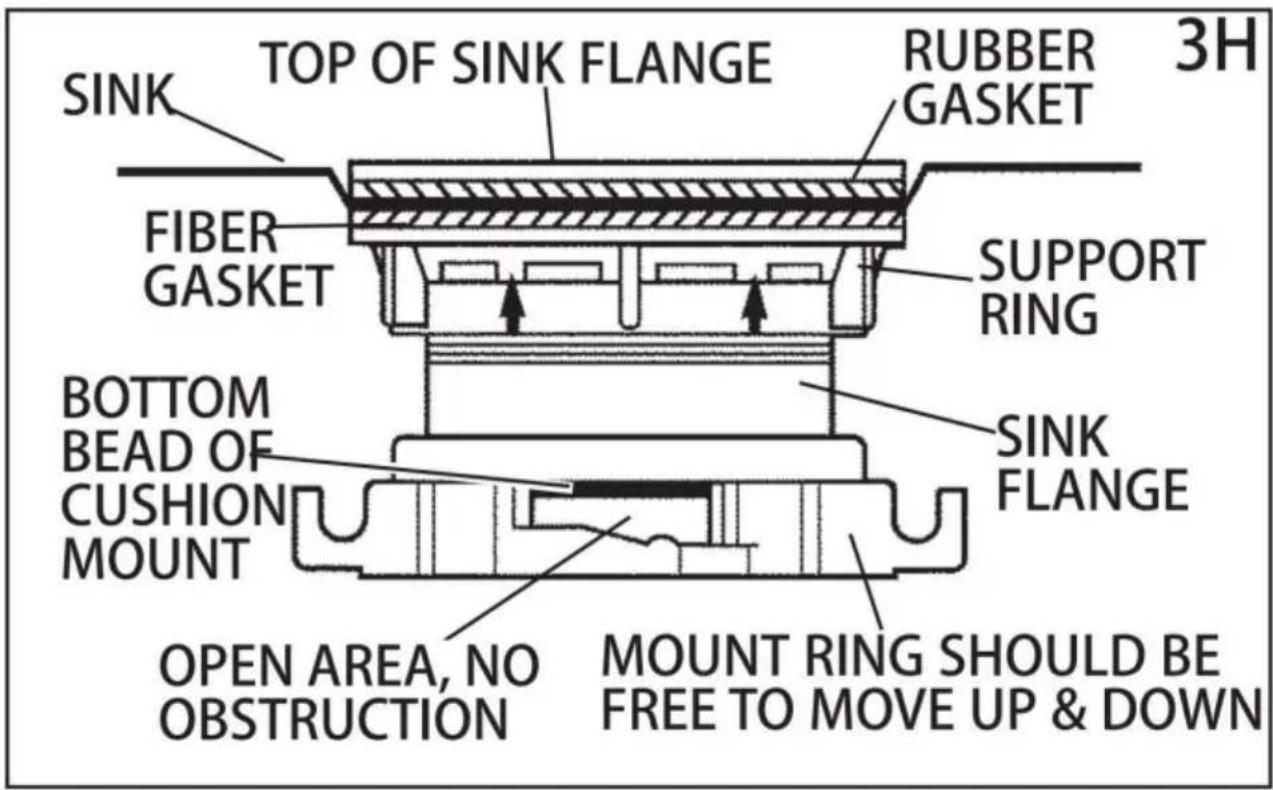
natural_image
Line drawing of a hand using a wrench to adjust a U-shaped pipe fitting (no text or symbols)6. AANSLUITEN VAN DE AFVOER OP DE MONTAGE-EENHEID
natural_image
Line drawing of a hand holding a U-shaped pipe fitting with a mechanical component above (no text or symbols)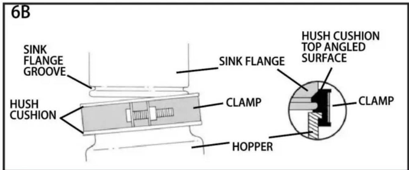
flowchart
graph TD
    A["SLOT"] --> B["PROJECTION"]
    B --> C["6C"]
natural_image
Illustration of hands assembling a mechanical component with a rotating arrow (no text or symbols)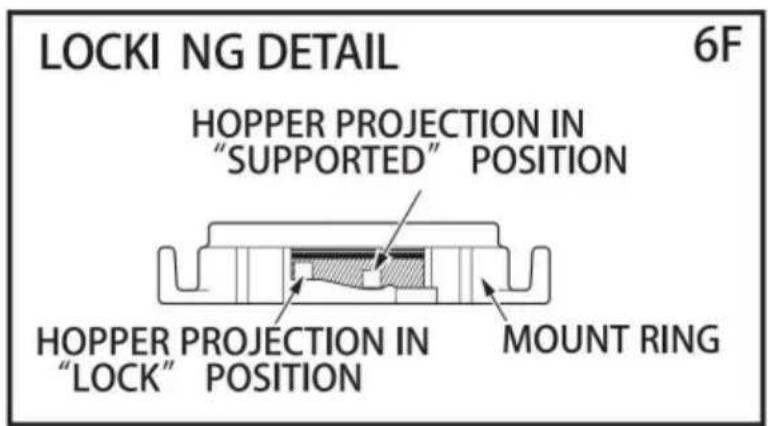
natural_image
Close-up of a black cylindrical mechanical component with metallic top and mounting holes (no visible text or symbols)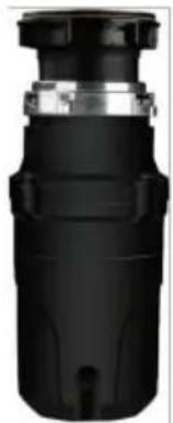
natural_image
Close-up of a black cylindrical mechanical component with metallic top and central hub (no visible text or symbols)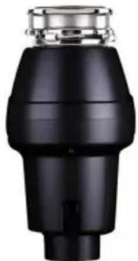
natural_image
Black industrial pipe fitting with metallic top (no visible text or symbols)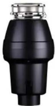
natural_image
Black industrial component with metallic top and stepped shaft (no visible text or symbols)JWM-331 JWM-331DCNJW-301DCNJV
natural_image
Close-up of a black mechanical component with metallic top and cylindrical body (no visible text or symbols)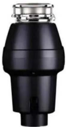
natural_image
Close-up of a black industrial pipe fitting with metallic fittings (no visible text or symbols)JWM-V50 JWM-V50A JW-V50
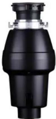
natural_image
Black mechanical component with a cylindrical body and flange (no visible text or symbols)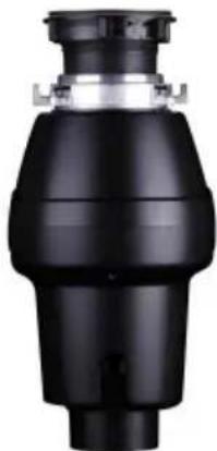
natural_image
Black industrial valve component with no visible text or symbolsJW-V50A
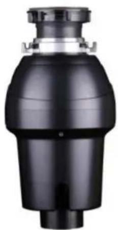
natural_image
Close-up of a black industrial valve or pump component with a cylindrical inlet (no visible text or symbols)JW-731
natural_image
Black industrial pipe fitting with a cylindrical top and flange (no visible text or symbols)JW-731DCN JWM-931 JWM-931DCN
natural_image
Black cylindrical mechanical component with metallic top and stepped base (no visible text or symbols)
natural_image
Black cylindrical mechanical component with metallic top and stepped base (no visible text or symbols)BEHÖVER HJÄLP? KONTAKTA OSS!
www.vevor.com/support
natural_image
Line drawing of a screwdriver with a flathead end (no text or symbols)PHILLIPS & FLATBLADE SCREWDRIVER
natural_image
Line drawing of a hand using a saw (no text or symbols)HACKSAW
natural_image
Simple line drawing of a cylindrical object with a protruding handle (no text or symbols)PLUMBER'S PUTTY
natural_image
Line drawing of three identical rectangular storage units with circular top caps, arranged horizontally (no text or symbols)DISHWASHER CONNECTOR KIT
natural_image
Line drawing of a hammer with textured handle and curved blade (no text or symbols)HAMMER
natural_image
Line drawing of an adjustable wrench tool (no text or symbols)PIPE WRENCH

DOW EL OR
STEEL PUNCH
natural_image
Black and white illustration of a coiled electrical plug with two terminal leads (no text or symbols)POWER CORD
STRAIN RELIEF
VIKTIGA SÄKERHETSINSTRUKTIONER
INSTRUKTIONER AVSEENDE RISK FÖR BRAND, ELEKTRISK STÖT ELLER SKADA TOPERSONS. SPARA DESSA INSTRUKTIONER.
natural_image
Diagram of a hand connecting a U-shaped pipe with a wrench, labeled '1A' (no text or symbols on the diagram itself)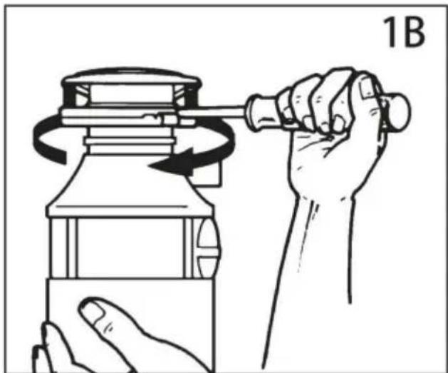
natural_image
Illustration of a hand using a tool to lift a cylindrical object, showing rotational motion (no text or symbols)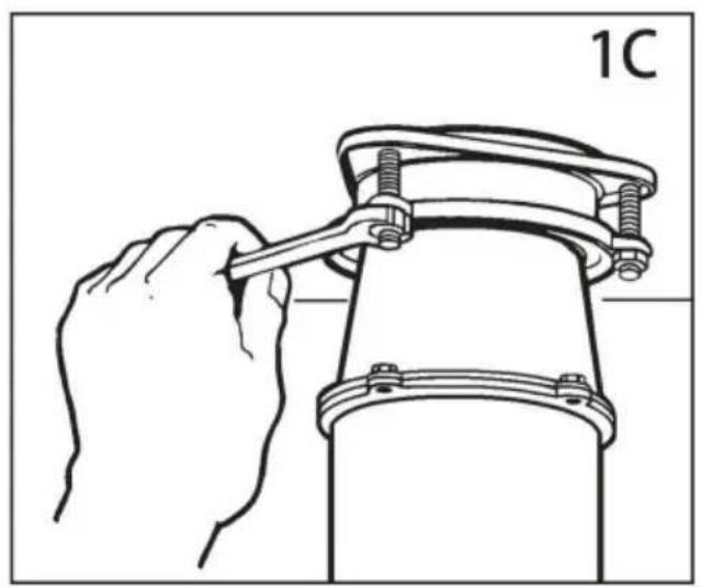
natural_image
Line drawing of a hand using a wrench to lift a mechanical component (no text or symbols)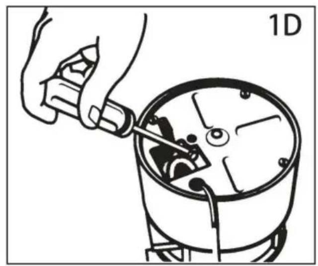
natural_image
Illustration of a hand using a tool to adjust or install a mechanical component, labeled '1D' (no text or symbols on the diagram itself)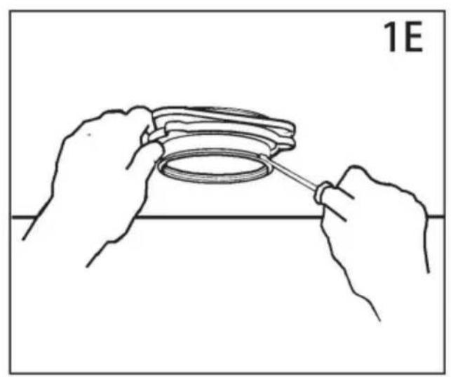
natural_image
Line drawing of hands assembling a circular component with a tool, labeled '1E' (no text or symbols on the diagram itself)2. ANSLUTNING AV DISKMASKINEN
3. INSTALLATION AV MONTERINGSMONTERING
DIN AVFALLSHÄLLARE MEDFÖLJER ETT AV FÖLJANDE FÄSTE SYSTEM
natural_image
Line drawing of two hands holding a circular object with a magnified inset showing internal features (no text or symbols)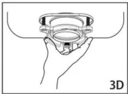
natural_image
Line drawing of a hand holding a 3D mechanical component (no text or symbols)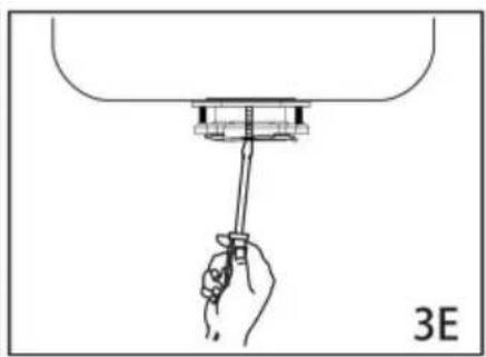
natural_image
Hand holding a tool above a mechanical component, labeled '3E' (no text or symbols on the diagram itself)EZ monteringssystem
LÄS RIKTIGT INNAN ATT STARTA
VIKTIGT MEDDELANDE: DETALJ FÖR KUDDMONTERING
natural_image
Illustration of hands assembling a mechanical component labeled '3G' (no text or symbols on the diagram itself)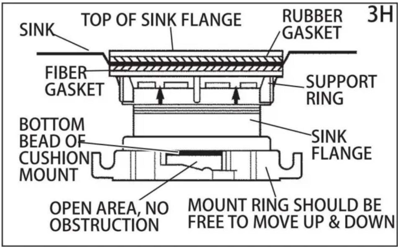
4. ELEKTRISKA ANSLUTNINGAR
natural_image
Line drawing of a hand using a wrench to adjust a U-shaped pipe fitting (no text or symbols)6. ANSLUTNING AV AVFALLSHÅLLARE TILL MONTERINGSMONTERING
natural_image
Diagram of a hand holding a pipe fitting with a valve assembly (no text or symbols)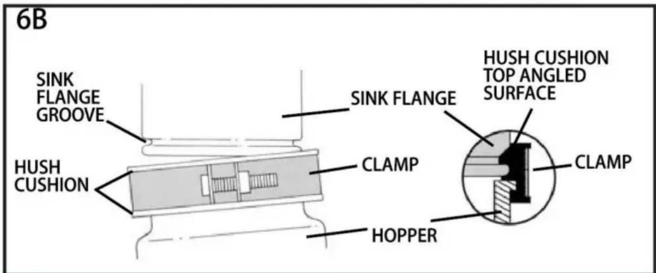
flowchart
graph TD
    A["SLOT"] --> B["PROJECTION"]
    B --> C["6C"]
natural_image
Illustration of hands assembling a mechanical component with a rotating arrow (no text or symbols)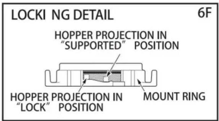
7. DRIFTSINSTRUKTIONER
natural_image
Illustration of a hand washing a dish with granular contents, no text or symbols present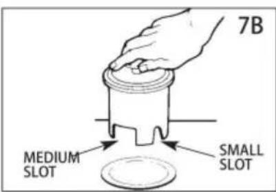
8. FELSÖKNING
www.vevor.com/support
- Garbage Disposal
- VEVOR®
- NEED HELP? CONTACT US!
- Please read this manual carefully before use!
- GROUNDING INSTRUCTIONS
- See insert for specific information about your new disposer
- NOTE:
- IMPORTANT:
- CAUTION:
- Tools and materials you may need
- IMPORTANT SAFETYINSTRUCTIONS
- REMOVAL OF OLD UNIT
- DISHWASHER CONNECTION
- INSTALLATION OF MOUNTING ASSEMBLY
- 3-Bolt Mount System
- EZ Mount System
- READ CO MPLETELY BEFORE STARTING
- IMPORTANT NOTICE: CUSHION MOUNT DETAIL
- ELECTRICAL CONNECTIONS
- ATTACHING DISCHARGE ELBOW
- CONNECTING DISPOSER TO MOUNT ASSEMBLY
- 3-BOLT MOUNT(See section 3 for your mount type.)
- IMPORTANT-PLEASE READ
- EZ MOUNT(See section 3 for your mount type.)
- OPERATING INSTRUCTIONS
- BATCH FEED OPERATING INSTRUCTIONS
- TROUBLESHOOTING
- CLEANING AND MAINTENANCE
- TOUGH TOOLS, HALF PRICE
- BESOIN D'AIDE? CONTACTEZ-NOUS!
- CONSIGNES DE SÉCURITÉ IMPORTANTES
- RACCORDEMENT LAVE-VAISSELLE
- INSTALLATION DE L'ENSEMBLE DE MONTAGE
- AVIS IMPORTANT : DÉTAIL DU SUPPORT DE COUSSIN
- RACCORDEMENT DU DISPOSITIF DE DÉCHET AU SUPPORT
- Machine Translated by Google
- INSTRUCTIONS D'UTILISATION
- DÉPANNAGE
- MONTAGE DER MONTAGEBAUGRUPPE
- EZ-Montagesystem
- VOR DEM START VOLLSTÄNDIG LESEN
- FEHLERSUCHE
- IMPORTANTI ISTRUZIONI DI SICUREZZA
- AVVISO IMPORTANTE: DETTAGLIO DEL MONTAGGIO DEL CUSCINO
- COLLEGAMENTI ELETTRICI
- COLLEGAMENTO DEL DISPOSITIVO AL GRUPPO DI MONTAGGIO
- ISTRUZIONI PER L'USO
- RISOLUZIONE DEI PROBLEMI
- AVISO IMPORTANTE: DETALLE DEL SOPORTE DEL COJÍN
- CONEXIONES ELÉCTRICAS
- INSTRUCCIONES DE USO
- POTRZEBUJESZ POMOCY? SKONTAKTUJ SIĘ Z NAMI!
- WAŻNE INSTRUKCJE BEZPIECZEŃSTWA
- PODŁĄCZENIE ZMYWARKI
- MONTAŻ ZESTAWU MONTAŻOWEGO
- WAŻNA INFORMACJA: SZCZEGÓŁY MOCOWANIA PODUSZKI
- PODŁĄCZANIE ROZDRABNIACZA DO ZESTAWU MONTAŻOWEGO
- INSTRUKCJA OBSŁUGI
- HULP NODIG? NEEM CONTACT MET ONS OP!
- BELANGRIJKE VEILIGHEIDSINSTRUCTIES
- AANSLUITING VAATWASSER
- INSTALLATIE VAN DE MONTAGE-EENHEID
- EZ-montagesysteem
- LEES HET VOLLEDIG DOOR VOORDAT U BEGINT
- BELANGRIJKE OPMERKING: DETAIL VAN DE KUSSENMONTAGE
- AANSLUITEN VAN DE AFVOER OP DE MONTAGE-EENHEID
- BEHÖVER HJÄLP? KONTAKTA OSS!
- VIKTIGA SÄKERHETSINSTRUKTIONER
- ANSLUTNING AV DISKMASKINEN
- INSTALLATION AV MONTERINGSMONTERING
- EZ monteringssystem
- LÄS RIKTIGT INNAN ATT STARTA
- VIKTIGT MEDDELANDE: DETALJ FÖR KUDDMONTERING
- ELEKTRISKA ANSLUTNINGAR
- ANSLUTNING AV AVFALLSHÅLLARE TILL MONTERINGSMONTERING
- DRIFTSINSTRUKTIONER
- FELSÖKNING
Brand : Vevor
Model : JW301
Category : Trash can