INPL4822SSNBB - Basket FABER - Free user manual and instructions
Find the device manual for free INPL4822SSNBB FABER in PDF.
User questions about INPL4822SSNBB FABER
0 question about this device. Answer the ones you know or ask your own.
Ask a new question about this device
Download the instructions for your Basket in PDF format for free! Find your manual INPL4822SSNBB - FABER and take your electronic device back in hand. On this page are published all the documents necessary for the use of your device. INPL4822SSNBB by FABER.
USER MANUAL INPL4822SSNBB FABER
natural_image
Technical line drawing of a rectangular metal enclosure or support structure (no text or symbols)INCA PRO PLUS
Installation Instructions Use and Care Information
READ AND SAVE THESE INSTRUCTIONS BEFORE YOU START INSTALLING THIS RANGEHOOD
WARNING: - TO REDUCE THE RISK OF A RANGE TOP GREASE FIRE:
a) Never leave surface units unattended at high settings. Boilovers cause smoking and greasy spillovers that may ignite. Heat oils slowly on low or medium setting.
b) Always turn hood ON when cooking at high heat or when flambeing food (i.e. Crepes Suzette, Cherries Jubilee, Peppercorn Beef Flambé).
c) Clean ventilating fans frequently. Grease should not be allowed to accumulate on fan or filter.
d) Use proper pan size. Always use cookware appropriate for the size of the surface element.
WARNING: - TO REDUCE THE RISK OF INJURY TO PERSONS IN THE EVENT OF A RANGE TOP GREASE FIRE, OBSERVE THE FOLLOWING*:
a) SMOTHER FLAMES with a close-fitting lid, cookie sheet, or metal tray, then turn off the burner. BE CAREFUL TO PREVENT BURNS. If the flames do not go out immediately EVACUATE AND CALL THE FIRE DEPARTMENT.
b) NEVER PICK UP A FLAMING PAN - You may be burned.
c) DO NOT USE WATER, including wet dishcloths or towels - a violent steam explosion will result.
d) Use an extinguisher ONLY if:
1. You know you have a Class ABC extinguisher, and you already know how to operate it.
2. The fire is small and contained in the area where it started.
3. The fire department is being called.
4. You can fight the fire with your back to an exit.
* Based on "Kitchen Firesafety Tips" published by NFPA
WARNING - TO REDUCE THE RISK OF FIRE OR ELECTRIC SHOCK, do not use this fan with any solid-state speed control device.
WARNING - TO REDUCE THE RISK OF FIRE, ELECTRIC SHOCK, OR INJURY TO PERSONS, OBSERVE THE FOLLOWING:
a) Use this unit only in the manner intended by the manufacturer. If you have any questions, contact the manufacturer.
b) Before servicing or cleaning unit, switch power off at service panel and lock the service disconnecting means to prevent power from being switched on accidentally.
When the service disconnecting means cannot be locked, securely fasten a prominent warning device, such as a tag, to the service panel.
CAUTION: For General Ventilating Use Only. Do Not Use To Exhaust Hazardous or Explosive Materials and Vapors.
WARNING - TO REDUCE THE RISK OF FIRE, ELECTRICAL SHOCK, OR INJURY TO PERSONS, OBSERVE THE FOLLOWING:
- Installation Work And Electrical Wiring Must Be Done By Qualified Person(s) In Accordance With All Applicable Codes And Standards, Including Fire-Rated Construction.
- Sufficient air is needed for proper combustion and exhausting of gases through the flue (chimney) of fuel burning equipment to prevent backdrafting. Follow the heating equipment manufacturer's guideline and safety standards such as those published by the National Fire Protection Association (NFPA), and the American Society for Heating, Refrigeration and Air Conditioning Engineers (ASHRAE), and
the local code authorities.
- When cutting or drilling into wall or ceiling, do not damage electrical wiring and other hidden utilities.
- Ducted fans must always be vented to the outdoors.
ALL WALL AND FLOOR OPENINGS WHERE THE RANGEHOOD IS INSTALLED MUST BE SEALED.
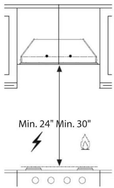
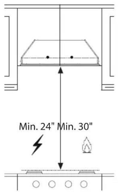
This rangehood requires at least 24" of clearance between the bottom of the rangehood and the cooking surface or countertop. This hood has been approved by UL at this distance from the cooktop. The maximum depth of overhead cabinets is 13".
Consult the cooktop or range installation instructions given by the manufacturer before making any cutouts. MOBILE HOME INSTALLATION The installation of this rangehood must conform to the Manufactured Home Construction and Safety Standards, Title 24 CFR, Part 3280 (formerly Federal Standard for Mobile Home Construction and Safety, Title 24, HUD, Part 280). Four wire power supply must be used and the appliance wiring must be revised. See Electrical Requirements.
VENTING REQUIREMENTS
Determine which venting method is best for your application. Ductwork can extend either through the wall or the roof.
The length of the ductwork and the number of elbows should be kept to a minimum to provide efficient performance. The size of the ductwork should be uniform. Do not install two elbows together. Use duct tape to seal all joints in the ductwork system. Use caulking to seal exterior wall or floor opening around the cap.
Flexible ductwork is not recommended. Flexible ductwork creates back pressure and air turbulence that greatly reduces performance.
Make sure there is proper clearance within the wall or floor for exhaust duct before making cutouts. Do not cut a joist or stud unless absolutely necessary. If a joist or stud must be cut, then a supporting frame must be constructed.
WARNING - To Reduce The Risk Of Fire, Use Only Metal Ductwork.
CAUTION - To reduce risk of fire and to properly exhaust air, be sure to duct air outside – Do not vent exhaust air into spaces within walls or ceilings or into attics, crawl spaces, or garages.
Cold Weather installations
An additional back draft damper should be installed to minimize backward cold air flow and a nonmetallic thermal break should be installed to minimize conduction of outside temperatures as part of the vent system. The damper should be on the cold air side of the thermal break. The break should be as close as possible to where the vent system enters the heated portion of the house.

WARNING
- Venting system MUST terminate outside the home.
- DO NOT terminate the ductwork in an attic or other enclosed space.
- DO NOT use 4" laundry-type wall caps.
- Flexible-type ductwork is not recommended.
- DO NOT obstruct the flow of combustion and ventilation air.
- Failure to follow venting requirements may result in a fire.
ELECTRICAL REQUIREMENTS
A 120 volt, 60 Hz AC-only electrical supply is required on a separate 15 amp fused circuit. A time-delay fuse or circuit breaker is recommended. The fuse must be sized per local codes in accordance with the electrical rating of this unit as specified on the serial/rating plate located inside the unit near the field wiring compartment.
ELECTRICAL INSTALLATION WITH WIRING BOX
THIS UNIT MUST BE CONNECTED WITH COPPER WIRE ONLY. Wire sizes must conform to the requirements of the National Electrical Code, ANSI/NFPA 70 - latest edition, and all local codes and ordinances. Wire size and connections must conform with the rating of the appliance. Copies of the standard listed above may be obtained from:
National Fire Protection Association
Batterymarch Park
Quincy, Massachusetts 02269
This appliance should be connected directly to the fused disconnect (or circuit breaker) through flexible, armored or nonmetallic sheathed copper cable. Allow some slack in the cable so the appliance can be moved if servicing is ever necessary. A UL Listed, 1/2" conduit connector must be provided at each end of the power supply cable (at the appliance and at the junction box).
When making the electrical connection, cut a 1 1/4" hole in the wall. A hole cut through wood must be sanded until smooth. A hole through metal must have a grommet.

WARNING
- Electrical ground is required on this rangehood.
- If cold water pipe is interrupted by plastic, nonmetallic gaskets or other materials, DO NOT use for grounding.
• DO NOT ground to a gas pipe. - DO NOT have a fuse in the neutral or grounding circuit. A fuse in the neutral or grounding circuit could result in electrical shock.
- Check with a qualified electrician if you are in doubt as to whether the rangehood is properly grounded.
- Failure to follow electrical requirements may result in a fire.
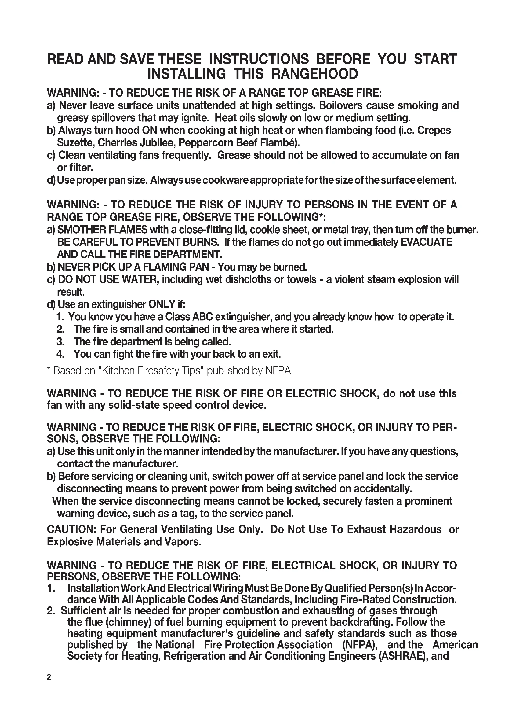
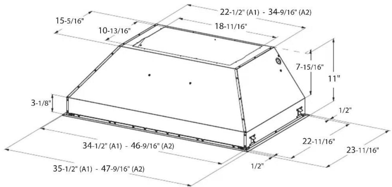
RANGEHOOD DIMENSIONS
text_image
21-1/4" (A1) - 22-1/2" (A2) 28-9/16" (A3) - 34-9/16" (A4) 12-5/16" 10-13/16" 18-11/16" 7-15/16" 11" 3-1/8" 1/2" 28-1/2" (A1) - 34-1/2" (A2) 40-9/16" (A3) - 46-9/16" (A4) 1/2" 29-1/2" (A1) - 35-1/2" (A2) 41-9/16" (A3) - 47-9/16" (A4) 19-11/16" 20-11/16"| Index | Model # |
| A1 | INPL3019SSNB-B |
| A2 | INPL3619SSNB-B |
| A3 | INPL4219SSNB-B |
| A4 | INPL4819SSNB-B |

text_image
22-1/2" (A1) - 34-9/16" (A2) 18-11/16" 15-5/16" 10-13/16" 7-15/16" 11" 3-1/8" 1/2" 22-11/16" 23-11/16" 34-1/2" (A1) - 46-9/16" (A2) 1/2" 35-1/2" (A1) - 47-9/16" (A2)| Index | Model # |
| A1 | INPL3622SSNB-B |
| A2 | INPL4822SSNB-B |
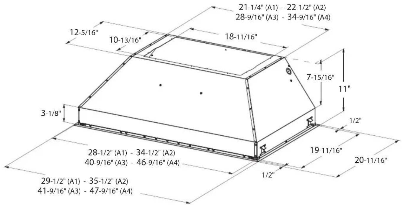
MAIN PARTS
text_image
Technical diagram of a multi-layered device with numbered components and assembly detailsComponents
Ref. Qty. Product Components
| 1 | 1 | Hood Body, complete with:Controls, Light, Filters, Blower. |
| 4 | 2 | Front / back trim |
| 5 | 2 | Left/right trim |
| 6 | 2 | Grease filters (30") |
| 6 | 3 | Grease filters (36"- 42") |
| 6 | 4 | Grease filters (48") |
| 7 | 4 | Filter knobs (30") |
| 7 | 6 | Filter knobs (36"- 42") |
| 7 | 8 | Filter knobs (48") |
| 8 | 1 | Grease rail |
| 10 | 10 | Stopper |
Ref. Qty. Installation Components
| 9c | 14 | Install screws (1/8"x1/4") |
| 9d | 6 | Install screws (1/8"x5/16") |
| 9e | 4 | Grease filters screws (3/16"x5/16" - 30") |
| 9e | 6 | Grease filters screws (5/32"x5/16" - 36"- 42") |
| 9e | 8 | Grease filters screws (5/32"x5/16" - 48") |
Qty. Documentation
1 Instruction Manual
Available
Accessories
Activated Charcoal Filter sku #; FILTER1
Internal 300 cfm Blower sku #; IB300
Internal 600 cfm PRO Blower sku #; IB600
Internal 1,200 cfm PRO Blower sku #; IB1200
Remote Blower 900 cfm sku #; RB900
Remote Blower 1,200 cfm sku #; RB1200
In-Line Blower Connection Kit sku #; INLBKIT
INSTALLATION
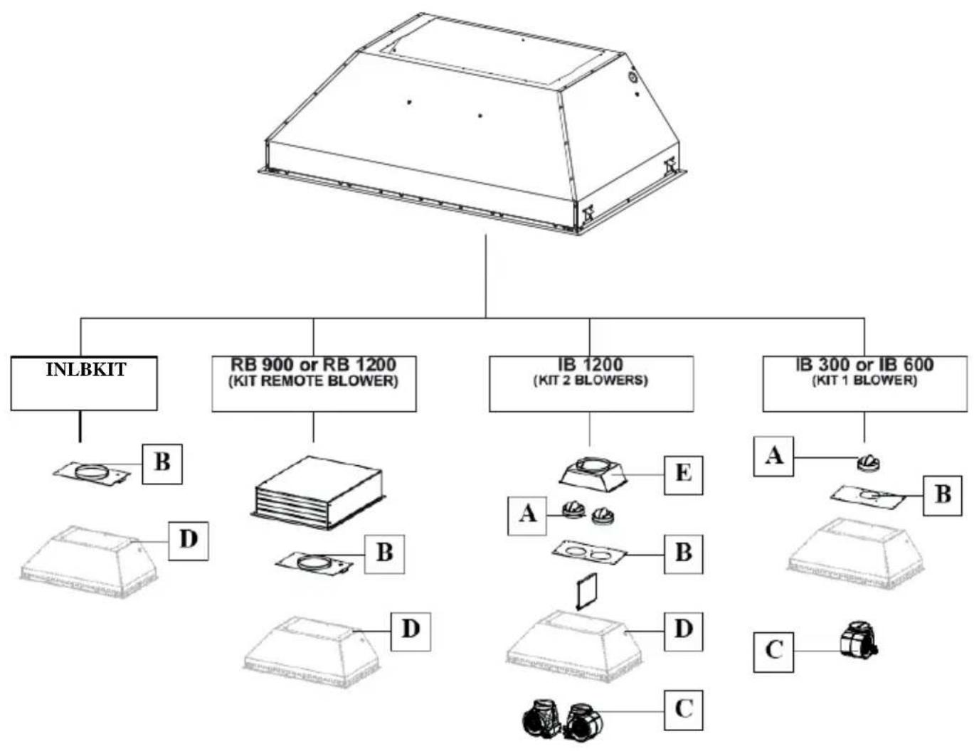
COMBINATIONS HOOD AND MOTOR KITS
flowchart
graph TD
    A["INLBKIT"] --> B["B"]
    B --> C["D"]
    C --> D["RD"]
    D --> E["B"]
    E --> F["D"]
    F --> G["RD"]
    G --> H["D"]
    H --> I["C"]
    I --> J["C"]
    J --> K["D"]
    K --> L["E"]
    L --> M["A"]
    M --> N["B"]
    N --> O["C"]
    O --> P["D"]
    P --> Q["E"]
    Q --> R["A"]
    R --> S["B"]
    S --> T["C"]
    T --> U["D"]
    U --> V["E"]
    V --> W["A"]
    W --> X["B"]
    X --> Y["C"]
    Y --> Z["D"]
    Z --> AA["E"]
    AA --> AB["A"]
For the 30" Inca it is recommended that blowers are kept at MAX. CFM of 600.
CAUTION - To reduce risk of fire and electric shock, install this rangehood only with: Remote blower manufacturer by Faber models RB900 and RB1200 or Internal blower manufactured by Faber models IB300 or IB600 or IB1200 or with INLBKIT and generic in-line blower rated max 4.2 A suitable for use with solid state variable speed control.
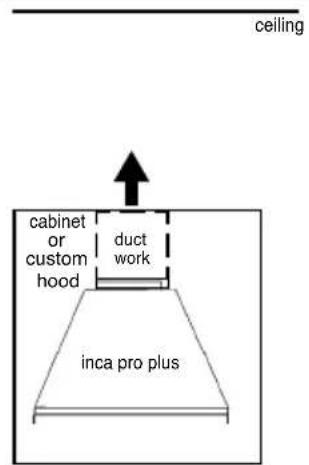
RECIRCULATING INSTALLATIONS
IT IS HIGHLY RECOMMENDED THAT PROFESSIONAL STYLE COOKING ALWAYS BE VENTED TO THE OUTSIDE. For recirculating installations (Figure 1), Charcoal Filters are necessary. Remove all grease filters and set aside. Attach one charcoal filter to each end of the blower. Each charcoal filter attaches to the grid on the side of the blower. Rotate the filter clockwise to install and counterclockwise to remove (Figure 1A). Replace all grease filters. Recirculating installations also require some duct work to divert the air out of the top or face or side of the cabinet or custom hood or out of the side / face of the soffit and back into the kitchen. Install at least 15" of vertical run of metal duct (Figure 1) at the air outlet. Run the duct vertically and secure it at the relevant opening previously cut out at the top or side of the cabinet or soffit. A metal duct cover grille is also recommended. The duct work must not terminate inside the cabinet or custom hood.
text_image
ceiling cabinet or custom hood duct work inca pro plus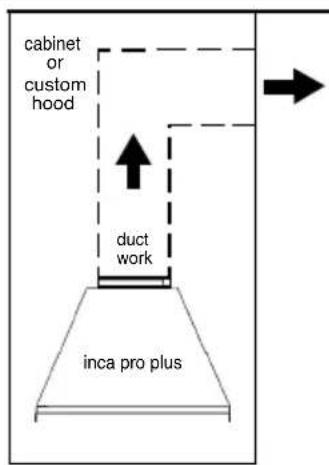
text_image
cabinet or custom hood duct work inca pro plus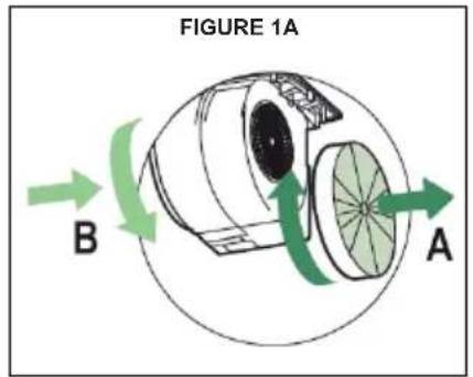
text_image
FIGURE 1A B AFIGURE 1
FOR ALL INSTALLATIONS REMOVE ALL WHITE PLASTIC PROTECTIVE COVERING FROM HOOD, SIDE RAILS, TRIM, GREASE RAILS AND GREASE FILTERS.
INSTALLATION WITH IB300 / IB600 INTERNAL BLOWER (300, 600 cfm)
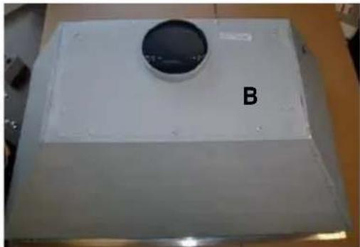
- Install the Plate B (Figure 2) which came with the internal blower kit, on top of the rangehood with the hole closer to the back of the hood. Use 9 screws supplied with the blower kit.
natural_image
White rectangular object with a circular top labeled 'B', placed on a flat surface (no other text or symbols visible)FIGURE 2
- Remove the white plastic covering and install the 4 side trim pieces (4-5) to the outside of the hood using (14) part 9c screws, see the side trim installation in (Figure 3).
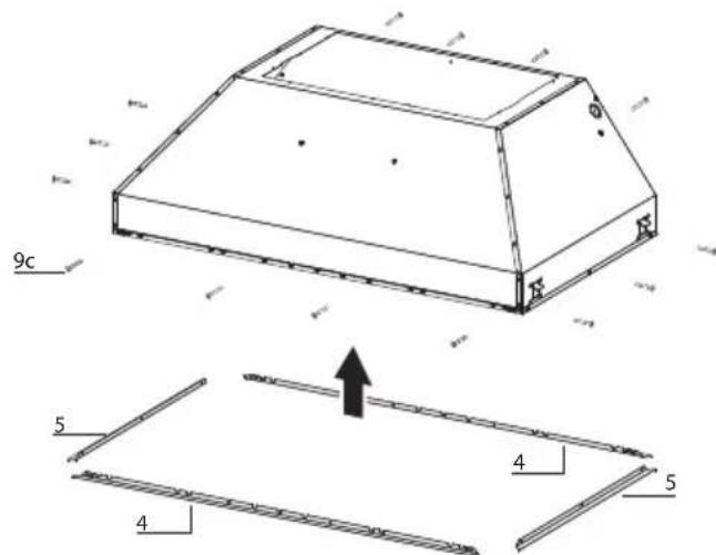
text_image
9c 5 4 5 4FIGURE 3
- Install the motor kit into the back of the hood using the 2 screws supplied with the motor kit (Figure 4).
natural_image
Technical line drawing of a mechanical assembly with two arrows indicating component positions (no text or symbols present)FIGURE 4
- Connect the wire cable D (which is located inside of Kit Internal 300 cfm Blower sku #; IB300 or Internal 600 cfm PRO Blower sku #; IB600). Connect the 6 hole end to the wire box and connect the 9 hole end to the motor (Figure 5).
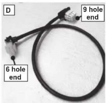
text_image
D 9 hole end 6 hole end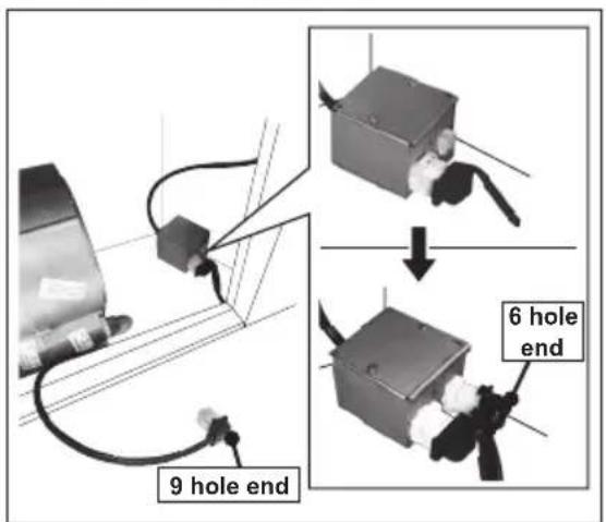
text_image
9 hole end 6 hole end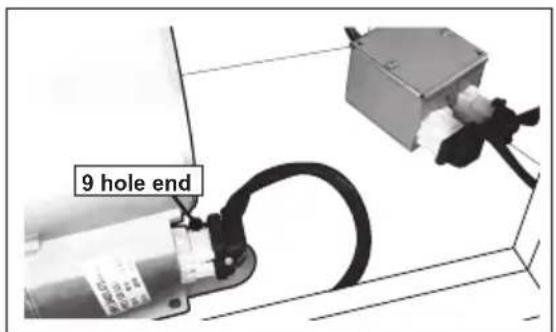
text_image
9 hole endFIGURE 5
-
Connect the ductwork to the damper and seal all connections with duct tape.
-
Before installing the hood, put the damper A (which is located inside of Kit Internal 300 cfm Blower sku #; IB300 or Internal 600 cfm PRO Blower sku #; IB600) (Figure 6).
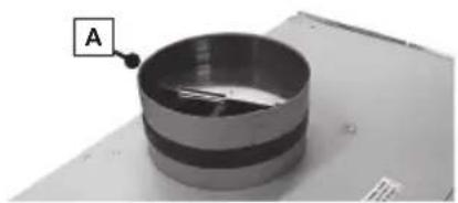
natural_image
Close-up of a metallic cylindrical object with a labeled point A pointing to it, placed on a flat surface (no text or symbols visible)FIGURE 6
INSTALLATION WITH IB1200 INTERNAL BLOWER (1200 cfm)
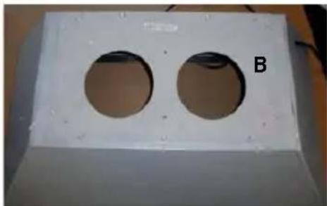
- Install the Duct Plate B (Figure 7) which came with the internal blower kit, on top of the rangehood with the holes located closer to the front. Use 9 screws supplied with the blower kit.
natural_image
White rectangular panel with two circular holes, labeled 'B' on the side (no other text or symbols visible)FIGURE 7
- Remove the white plastic covering and Install the 4 side trim pieces (4-5) to the outside of the hood using (14) part 9c screws, see the side trim installation in (Figure 8).
text_image
9c 5 4 5 4FIGURE 8
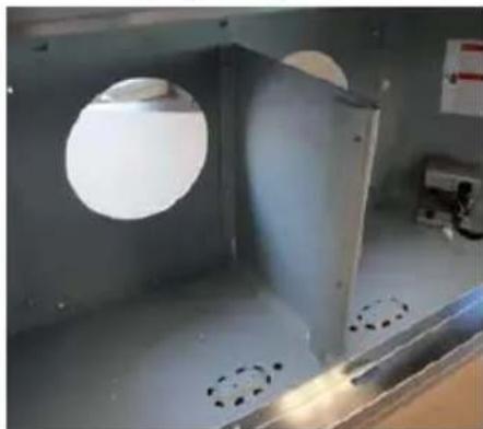
- Attach the blower bracket divider inside the hood with the 2 screws into the top of the hood and 2 screws into the back, all supplied with the blower kit (Figure 9).
natural_image
Interior view of a metallic industrial or laboratory chamber with circular light fixtures and perforated surfaces (no visible text or symbols)FIGURE 9
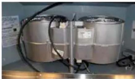
- Install the 2 motor kits into the sides of the blower bracket using the 4 screws supplied with the motor kit (Figure 10).
natural_image
Two large metallic cylindrical tanks with visible internal structures and wiring, placed on a metal shelf (no text or symbols)FIGURE 10
- Connect the wire cable D (which is located inside of Kit Internal 1,200 cfm PRO Blower sku #; IB1200). Connect the 6 hole end (A) to the wire box and connect the 9 hole end (B-C) to the two motors (Figure 11).
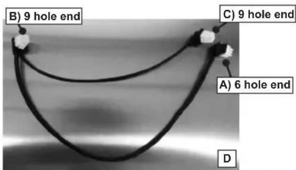
text_image
B) 9 hole end C) 9 hole end A) 6 hole end D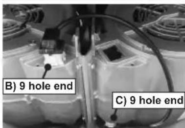
text_image
B) 9 hole end C) 9 hole end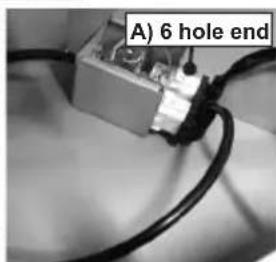
text_image
A) 6 hole endFIGURE 11
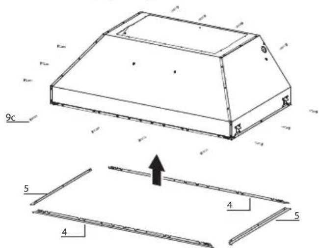
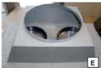
- Install the 2 dampers (A) on top of the hood (which is located inside of Kit Internal 1,200 cfm PRO Blower sku #; IB1200). Alternatively, install the 10" duct transition (E) (which is located inside of Kit Internal 1,200 cfm PRO Blower sku #; IB1200) and install with four screws (Figure 12).
natural_image
Exterior view of a metallic circular component mounted on a rectangular base (no visible text or symbols)FIGURE 12
- Follow step 4 on page 13 to connect ducting, wiring, and test the electrical connection.
INSTALLATION WITH REMOTE BLOWER (RB900 / RB1200) OR IN-LINE BLOWER (INLBKIT)
NOTE: FOLLOW THE INSTRUCTIONS INCLUDED WITH THE REMOTE BLOWER TO INSTALL THE BLOWER ON THE OUTSIDE OF YOUR HOME.
- Install the Plate B with the second wiring box (Figure 13) which came with the remote blower kit, on top of the rangehood. Use 9 screws supplied with the blower kit. Remove the electrical knockout hole on top of the plate.
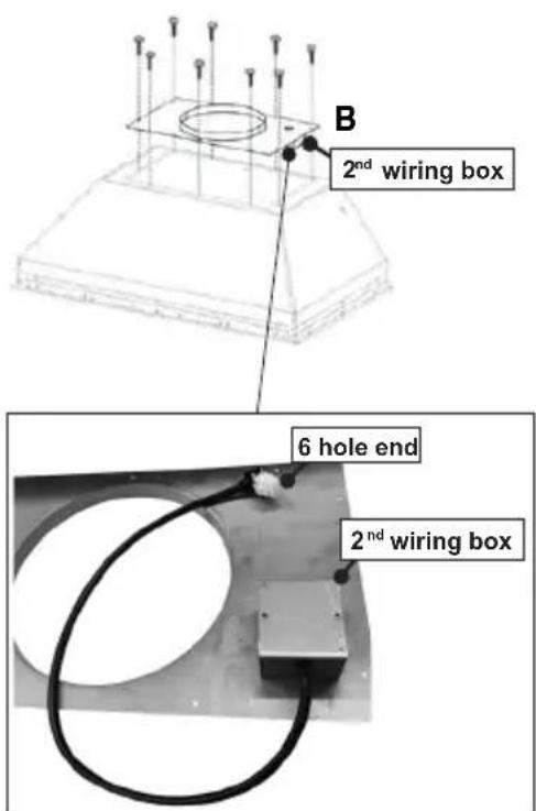
text_image
B 2nd wiring box 6 hole end 2nd wiring boxFIGURE 13
- Connect the wire coming out from the 2^nd wiring box to the 6 hole end of the 1^st wiring box.
Connect the wire that comes out from the black box of the electronic board to the 9 hole end of the 1^st wiring box (Figure 15).
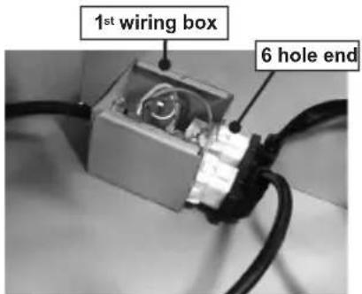
text_image
1st wiring box 6 hole endFIGURE 15
- Pass the remote blower cable through the knockout hole in step 1 (Figure 13,16). Connect this cable from the remote blower to the 2^nd wiring box placed on the lower surface of plate B.
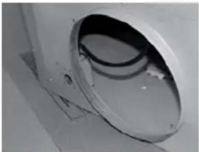
natural_image
Close-up of a white cylindrical mechanical component with internal cavity and mounting holes (no visible text or symbols)FIGURE 16
- Remove the white plastic covering and Install the 4 side trim pieces (4-5) to the outside of the hood using (14) part 9c screws, see the side rail installation in (Figure 14).
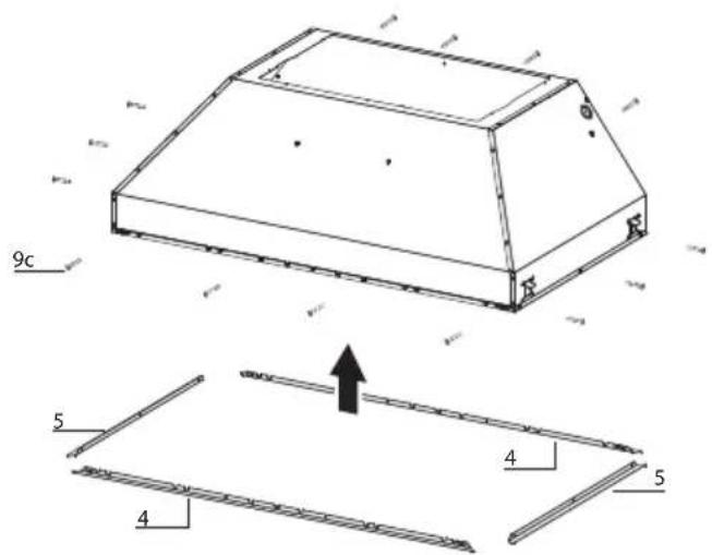
text_image
9c 5 4 5 4FIGURE 14
- Follow step 4 on page 13 to connect ducting, wiring, and test the electrical connection. Use the wiring box connected to the inside wall of the hood which connects to the home power supply thru the knockout on the side of the hood.
Installation Instructions
1
text_image
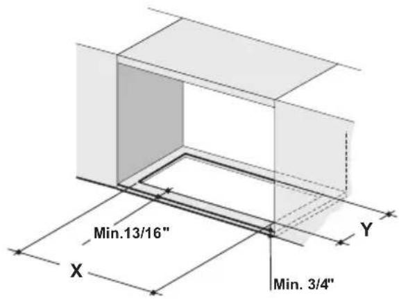
Min.13/16" X Y Min. 3/4"Cut out the opening in the underside of the cabinet as shown in Figure 1.
| Outside Hood Dimension | Model # | X | Y |
| 30" x 19" | INPL3019SSNB-B | 28-5/8" | 19-7/8" |
| 36" x 19" | INPL3619SSNB-B | 34-3/4" | 19-7/8" |
| 36" x 22" | INPL3622SSNB-B | 34-3/4" | 22-7/8" |
| 42" x 19" | INPL4219SSNB-B | 40-3/4" | 19-7/8" |
| 48" x 19" | INPL4819SSNB-B | 46-3/4" | 19-7/8" |
| 48" x 22" | INPL4822SSNB-B | 46-3/4" | 22-7/8" |
2
text_image
Min. 24" Min. 30"

OK!
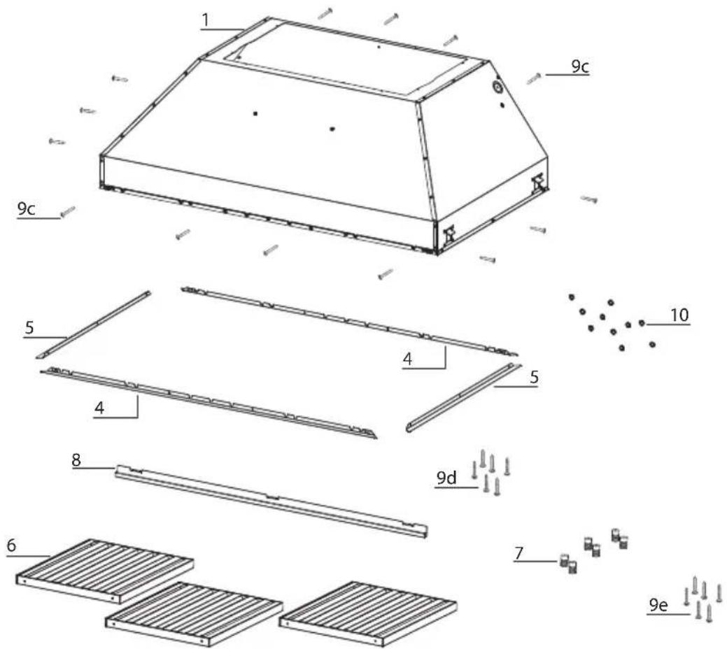
Two people may be required for installation.
text_image
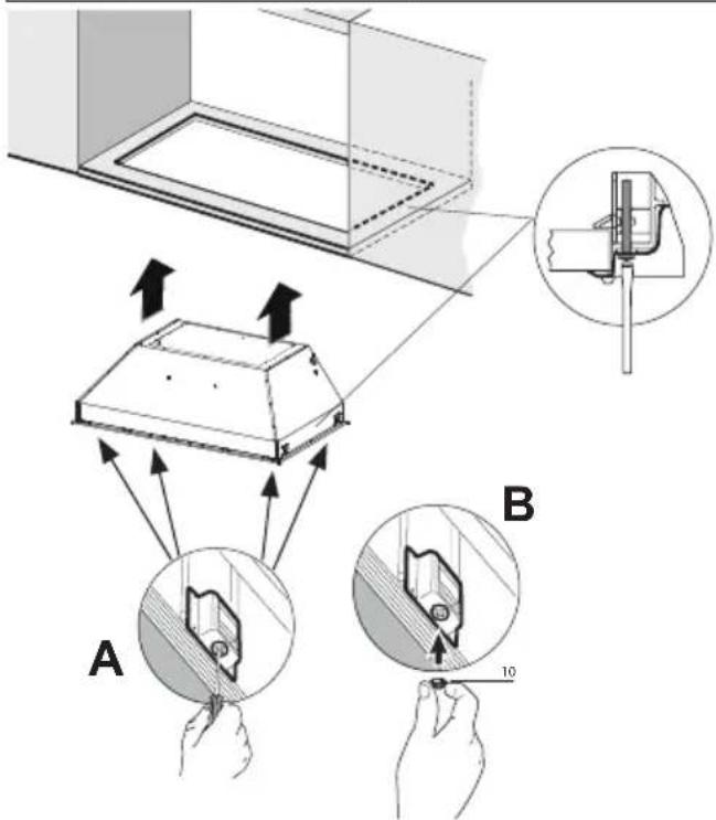
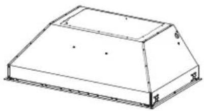
Diagram illustrating a device installation procedure with labeled components A and B, showing hand positioning and directional arrows.Install the Insert Hood through the cabinet cutout into the cabinet opening that has a minimum height of 16". Allow for ducting.
The range hood is secured to the cabinet cutout by two spring loaded brackets, one on each side of the range hood.
It is recommended that the Insert Hood is supported with a 3/4" wood base to insure proper alignment of the two side clips.
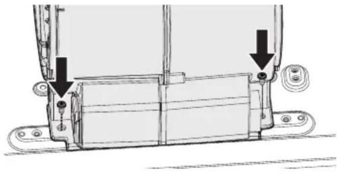
After the Insert Hood is installed into the cabinet opening lock it into position by tightening the indicated screws in each of the two side stoppers from underneath the Insert Hood.
Place the 4 stoppers (10) after securing the hood to the cabinet (Fig. 2A-B).
text_image
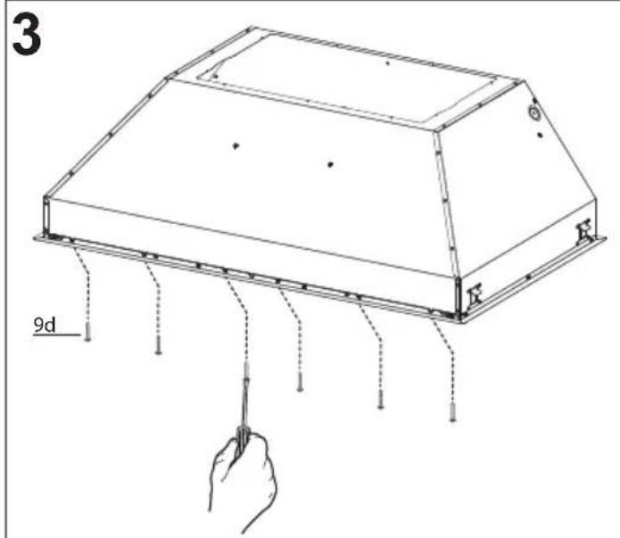
3 9d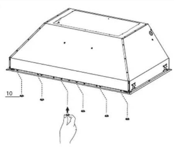
natural_image
Technical line drawing of a rectangular electronic device with mounting holes and a hand pointing to a terminal (no text or symbols)Fix the hood with 6 screws (9d). Place the 6 stoppers (10) after fixing the hood.
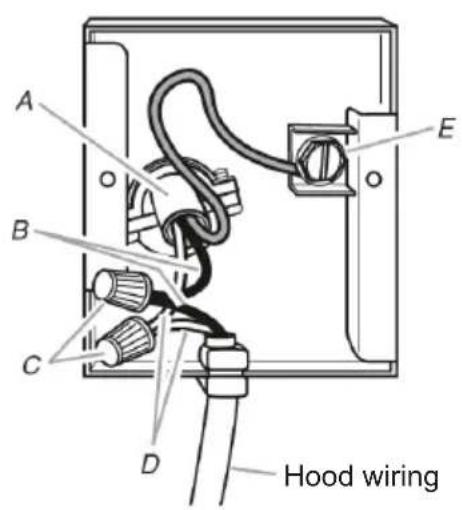
4 Installation of wiring connection
Remove the wiring electrical knockout using a flat-blade screwdriver. Feed the Power Supply Cable through the electrical knockout.
Connect the Power Supply Cable to the rangehood. Attach the White lead of the power supply (A) to the White lead of the rangehood (D) with a twist-on type wire connector. Attach the Black lead of the power supply to the Black lead of the rangehood (B) with a twist-on type wire connector (C). Connect the Green (E) (Green and Yellow) ground wire under the Green grounding screw.
Replace the field wiring compartment cover and the grease filters.
Connect the ductwork to the damper and seal all connections with duct tape.
Turn the power supply on. Turn on the blower and light. If the rangehood does not operate, check that the circuit breaker is not tripped or the house fuse blown. If the unit still does not operate, disconnect the power supply and check that the wiring connections have been made properly.
Reattach the field wiring compartment cover.
text_image
A B C D E Hood wiring5 For Non-Ducted Recirculation Option
Attach each charcoal filter to the black grid on each side of the blower.
Press the charcoal filter tightly to the black grid on the blower side and rotate the filter clockwise (towards the front of the insert hood) until it locks into place. Turn counterclockwise (towards the back of the insert hood) to remove.
natural_image
Technical line drawing of a rectangular metal enclosure or duct (no text or symbols)
text_image
1 2Replacing Activated Charcoal Filter
The Activated Charcoal Filters are not washable and cannot be regenerated, and should be replaced approximately every 4 months of operation, or more frequently with heavy usage. Remove the charcoal filter by rotating it clockwise (backwards) until it unlocks from the motor housing and pull off sideways.
To reinsert each charcoal filter, place up against the side of the blower and push it inward. Then turn the charcoal filter clockwise (forward) until it fits into place.
Required Activated Charcoal Filter Accessory - sku # - FILTER1 (purchased separately).
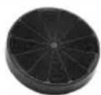
When used in recirculation mode, to Reduce the Risk of Fire and Shock use only conversion kit Model FILTER 1.
text_image
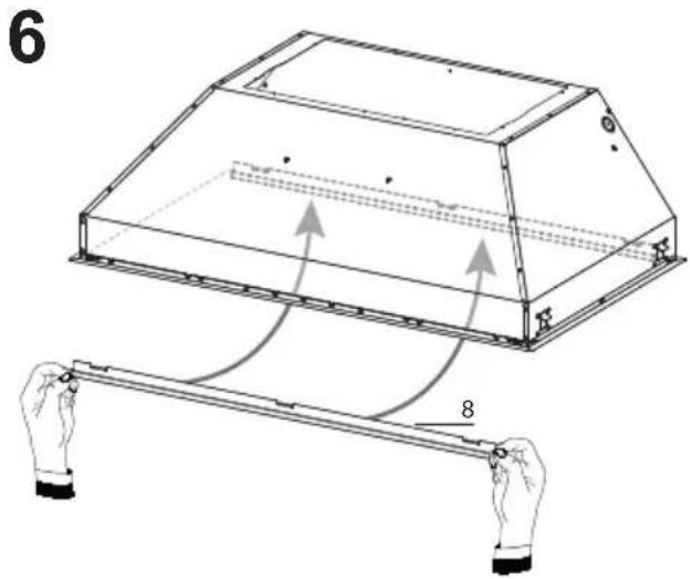
6 8Hook the Grease rail (8) positioning it inside the hood. Is possible wash and reposition inside the hood.
text_image
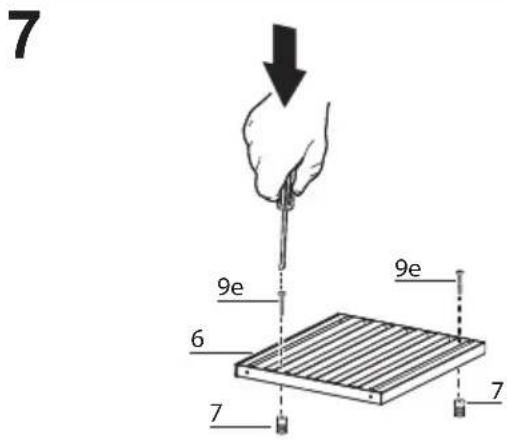
7 9e 6 7 9e 7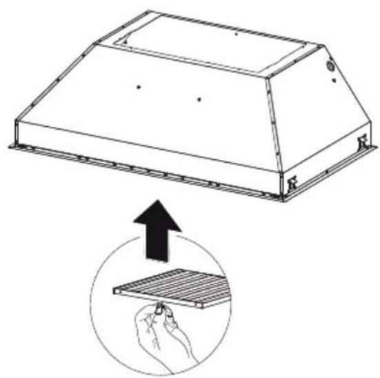
natural_image
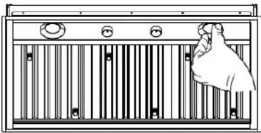
Technical line drawing of a roof structure with an inset showing a hand holding a grid panel (no text or symbols)Baffle Filter
Before putting the filters (6), tighten the 2 knobs (7) with 2 screws (9e).
Use two hands to insert and remove the filters.
Rangehood Control Panel
The control panel is located in the center of the hood bottom.
text_image
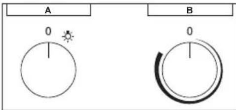
A 0 B 0Light On/Off Button (A)
On/Off switch for the lights. Position "0" turns the lights Off, turning the switch to the right is On.
Blower On/Off Button (B)
On/Off switch for the blower. Move the dial to the right to turn the blower ON and vary the speed of the blower. Turn to the left at "0" to turn it OFF.
For Best Result
Start the rangehood several minutes before cooking to develop proper airflow. Allow the unit to operate for several minutes after cooking is complete to clear all smoke and odors from the kitchen.
Cleaning
The stainless steel grease filters and grease rail should be cleaned frequently in hot detergent solution or washed in the dishwasher. Clean exterior surfaces with a commercially available stainless steel cleaner. Abrasives and scouring agents can scratch stainless steel finishes and should not be used to clean finished surfaces.
Grease rail and Grease Filter Installation / Removal.
Remove the plastic from the filter, the knobs need to be installed onto the filter with 2 screws to each filter.
Install the grease rail into the back of the hood, into the slots on the inside floor of the rear of the hood. The Grease filters should be installed before operating the rangehood. To install the filters, use the two knobs to hold the filter and insert the filter into the front edge of the hood with the knobs facing out into the spring loaded slot. Install the other end of the filter above the grease rail in the back of the hood.
text_image
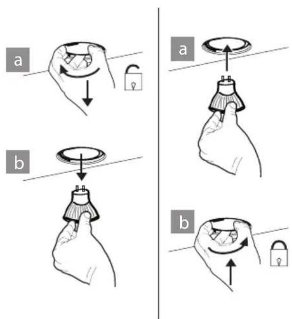
Diagram showing a hand holding a barcode with control buttons and tick marks, likely illustrating barcode or data filtering.Lighting unit
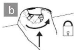
- Remove the snap-on lamp cover by levering it from under the metal ring, supporting it with one hand.
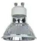
- Replace the lamp with a new one of the same type, making sure that you insert the two pins properly into the housings on the lamp holder.
- Replace the snap-on lamp cover.
text_image
a b a bGu10 self-ballasted led lamps
– listed in accordance with ul
1993/nmx-j-578/1-ance/csa
c22.2 No. 1993
Wiring Diagram
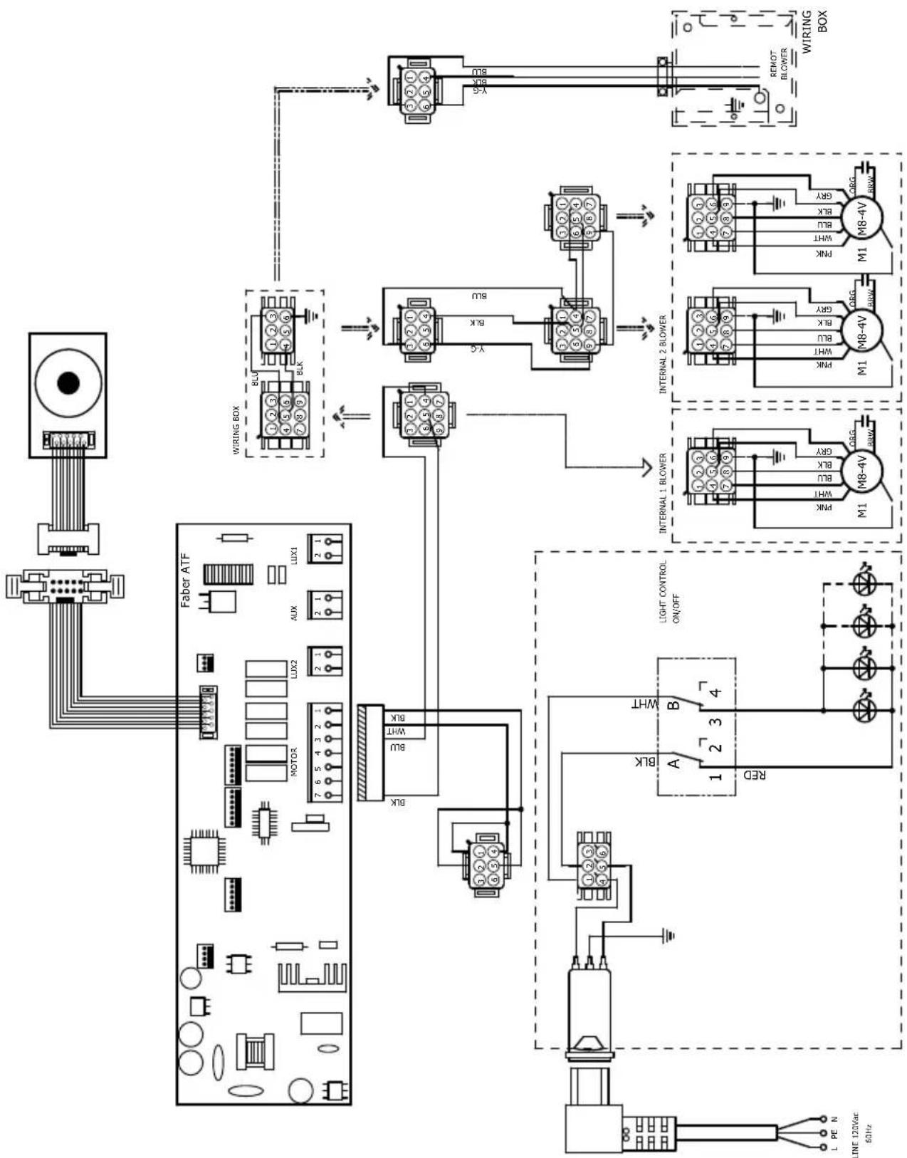
flowchart
graph TD
    A["LINE 120Vac 60Hz"] --> B["Motor"]
    B --> C["Faber ATF"]
    C --> D["WIRING BOX"]
    D --> E["Internal 1 BLOWER"]
    D --> F["Internal 2 BLOWER"]
    E --> G["M1 M8-4V"]
    F --> H["M1 M8-4V"]
    G --> I["ORG BRW"]
    H --> J["ORG BRW"]
    I --> K["ORG BRW"]
    J --> L["ORG BRW"]
    K --> M["ORG BRW"]
    L --> N["ORG BRW"]
    M --> O["ORG BRW"]
    N --> P["ORG BRW"]
    O --> Q["ORG BRW"]
    P --> R["ORG BRW"]
    Q --> S["ORG BRW"]
    R --> T["ORG BRW"]
    S --> U["ORG BRW"]
    T --> V["ORG BRW"]
    U --> W["ORG BRW"]
    V --> X["ORG BRW"]
    W --> Y["ORG BRW"]
    X --> Z["ORG BRW"]
    Y --> AA["ORG BRW"]
    Z --> AB["ORG BRW"]
FABER
FABER CONSUMER WARRANTY & SERVICE
All Faber products are warranted against any defect in materials or workmanship for the original purchaser for a period of 1 year from the date of original purchase (requires proof of purchase). This warranty covers labor and replacement parts. Faber, at its option, may repair or replace the product or components necessary to restore the product to good working condition. To obtain warranty service, contact the dealer from whom you purchased the range hood, or the local Faber distributor. If you cannot identify a local Faber distributor, contact us at (508) 358-5353 for the name of a distributor in your area.
The following is not covered by Faber's warranty:
- Service calls to correct the installation of your range hood, to instruct you how to use your range hood, to replace or repair house fuses or to correct house wiring or plumbing.
- Service calls to repair or replace range hood light bulbs, fuses or filters. Those consumable parts are excluded from warranty coverage.
- Repairs when your range hood is used for other than normal, single-family household use.
- Damage resulting from accident, alteration, misuse, abuse, fire, flood, acts of God, improper installation, installation not in accordance with electrical or plumbing codes or Faber documentation, or use of products not approved by Faber.
- Replacement parts or repair labor costs for units operated outside the United States or Canada, including any non-UL or C-UL approved Faber range hoods.
- Repairs to the hood resulting from unauthorized modifications made to the range hood.
- Expenses for travel and transportation for product service in remote locations and pickup and delivery charges. Faber range hoods should be serviced in the home.
THIS WARRANTY DOES NOT ALLOW RECOVERY OF INCIDENTAL OR CONSEQUENTIAL DAMAGES, INCLUDING, WITHOUT LIMITATION, DIRECT, INDIRECT, INCIDENTAL, SPECIAL OR CONSEQUENTIAL DAMAGES, PERSONAL INJURY/WRONGFUL DEATH OR LOST PROFITS FABER WARRANTY IS LIMITED TO THE ABOVE CONDITIONS AND TO THE WARRANTY PERIOD SPECIFIED HEREIN AND IS EXCLUSIVE. EXCEPT AS EXPRESSLY SPECIFIED IN THIS AGREEMENT, FABER DISCLAIMS ALL EXPRESS OR IMPLIED CONDITIONS, REPRESENTATIONS, AND WARRANTIES INCLUDING, WITHOUT LIMITATION, ANY IMPLIED WARRANTIES OF MERCHANTABILITY OR FITNESS FOR A PARTICULAR PURPOSE.
This warranty gives you specific legal rights that may vary from state to state.
Model#:
Serial #: ____
January 4, 2016
VEUILLEZ LIRE ET CONSERVER LA PRÉSENTE NOTICE AVANT DE COMMENCER L'INSTALLATION DE LA HOTTE DE CUISINE
AVERTISSEMENT:-POUR RÉDUIRE LE RISQUE D'UN FEU DE GRAISSE SUR LA TABLE DE CUISSON :
National Fire Protection Association
Batterymarch Park
text_image
21-1/4" (A1) - 22-1/2" (A2) 28-9/16" (A3) - 34-9/16" (A4) 12-5/16" 10-13/16" 18-11/16" 7-15/16" 11" 3-1/8" 1/2" 28-1/2" (A1) - 34-1/2" (A2) 40-9/16" (A3) - 46-9/16" (A4) 1/2" 29-1/2" (A1) - 35-1/2" (A2) 41-9/16" (A3) - 47-9/16" (A4) 19-11/16" 20-11/16"| Légende | Modèle # |
| A1 INPL30 | 19SSNB-B |
| A2 INPL36 | 19SSNB-B |
| A3 INPL42 | 19SSNB-B |
| A4 INPL48 | 19SSNB-B |
text_image
22-1/2" (A1) - 34-9/16" (A2) 18-11/16" 15-5/16" 10-13/16" 7-15/16" 11" 3-1/8" 1/2" 22-11/16" 23-11/16" 34-1/2" (A1) - 46-9/16" (A2) 35-1/2" (A1) - 47-9/16" (A2) 1/2"text_image
Technical diagram of a multi-layered structural assembly with numbered components and labeled partsComposants
INSTALLATIONS AVEC RECIRCULATION
natural_image
White rectangular object with a circular top labeled 'B', placed on a flat surface (no other text or symbols visible)FIGURE 2
natural_image
Technical diagram of a mechanical assembly with two arrows indicating connection points (no text or symbols present)FIGURE 4
natural_image
Close-up of a cylindrical mechanical component with a labeled section 'A' pointing to its edge (no other text or symbols visible)FIGURE 6
INSTALLATION AVEC LE VENTILATEUR IB1200 INTERNE (cfm 1200)
natural_image
White rectangular panel with two circular holes, labeled 'B' on the top (no other text or symbols visible)FIGURE 7
natural_image
Interior view of a technical enclosure with circular cutouts and floor markers (no visible text or symbols)FIGURE 9
natural_image
Two cylindrical industrial tanks with visible wiring and components, placed on a metal shelf (no text or symbols)FIGURE 10
natural_image
Exterior view of a modern office building (no signage)FIGURE 12
INSTALLATION AVEC LE VENTILATEUR À DISTANCE (RB900 / RB1200 OU VENTILATEUR INTÉGRÉ (INLBKIT)
NOTE : SUIVEZ LES INSTRUCTIONS INCLUDES AVEC LE VENTILATEUR À DISTANCE POUR INSTALLER LE VENTILATEUR SUR L'EXTÉRIEUR DE VOTRE MAISON.
natural_image
Close-up of a white cylindrical object with a circular opening, showing internal structure and mounting holes (no text or symbols visible)FIGURE 16
text_image
Min.13/16" X Y Min. 3/4"| Dimension extérieure de hotte | Modèle # | X | Y |
| 30" x 19" | INPL3019SSNB-B | 28-5/8" | 19-7/8" |
| 36" x 19" | INPL3619SSNB-B | 34-3/4" | 19-7/8" |
| 36" x 22" | INPL3622SSNB-B | 34-3/4" | 22-7/8" |
| 42" x 19" | INPL4219SSNB-B | 40-3/4" | 19-7/8" |
| 48" x 19" | INPL4819SSNB-B | 46-3/4" | 19-7/8" |
| 48" x 22" | INPL4822SSNB-B | 46-3/4" | 22-7/8" |
2
text_image
Min. 24" Min. 30"

OK!
text_image
Diagram illustrating a device installation procedure with labeled components A and B, showing hand positioning and directional arrows.natural_image
Technical line drawing of a rectangular electronic device with mounting holes and a hand gesture indicator (no text or symbols)text_image
Technical diagram showing a 3D component with an arrow indicating upward motion and two labeled parts (1 and 2) inside a circular opening.natural_image
Technical line drawing of a roof structure with an inset showing a hand holding a grid panel (no text or symbols)Filtre à chicane
text_image
Diagram showing a hand holding a barcode with control buttons and tick marksSystème d'éclairage
natural_image
Illustration of a hand holding a bulb with a circular top and pointer, no text or symbols present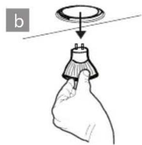
natural_image
Illustration of a hand holding a small electronic component with a circular top and arrow indicating direction (no text or symbols)