
Wärmepilz - Heating Sonnenkönig - Free user manual and instructions
Find the device manual for free Wärmepilz Sonnenkönig in PDF.
| Product Type | Patio and Garden Heater |
| Brand | Sonnenkönig |
| Model | Wärmepilz |
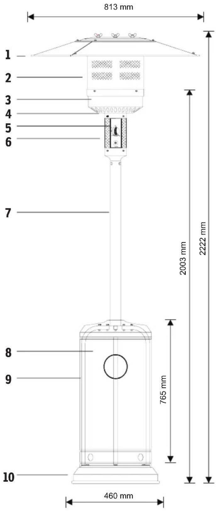
| Dimensions (H x W x D) | 2222 x 813 x 460 mm |
| Approximate weight | 18 kg |
| Power supply | Propane or butane (cylinder not included) |
| Maximum power | 13 kW |
| Minimum power | 5 kW |
| Power adjustment | Progressive (Pilot, Low, High) |
| Ignition | Piezo (without battery) |
| Material | Steel with powder coating |
| Safety | Flame detection (thermocouple), safety valve |
| Use | Outdoor only |
| Safety distance (sides / top) | 90 cm / 60 cm |
| Integrated tank | Yes (for gas cylinder) |
| Warranty | 2 years |
| Standards | CE, EN 14543:2017 |
Frequently Asked Questions - Wärmepilz Sonnenkönig
User questions about Wärmepilz Sonnenkönig
0 question about this device. Answer the ones you know or ask your own.
Ask a new question about this device
Download the instructions for your Heating in PDF format for free! Find your manual Wärmepilz - Sonnenkönig and take your electronic device back in hand. On this page are published all the documents necessary for the use of your device. Wärmepilz by Sonnenkönig.
USER MANUAL Wärmepilz Sonnenkönig
natural_image
Line drawing of a portable outdoor lighting fixture with a vertical support structure and control panel (no text or symbols)
FIRMA
Sonnenkönig of Switzerland
Olensbachstrasse 9-15
CH-9631 Ulisbach
Tel. Int. +41 58 611 60 00
Tel. Nat. 0848 870 850
Sonnenkönig of Switzerland
natural_image
Pure diagram of a vehicle suspension system with no text, numbers, or symbols
natural_image
Technical line drawing of a mechanical device with two vertical supports and downward arrows indicating force or movement (no text or symbols)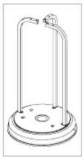
natural_image
Line drawing of a cylindrical mechanical device with two protruding rods and a base plate (no text or symbols)natural_image
Technical diagram of a mechanical assembly with multiple curved components and directional arrows indicating force or movement (no text or symbols present)
natural_image
Technical line drawing of a cylindrical mechanical component with a central hub and three vertical supports (no text or symbols)
natural_image
Line drawing of a cylindrical mechanical component with a central hole and a vertical rod (no text or symbols)natural_image
Technical line drawing of a mechanical component with a pin and directional arrows indicating assembly or alignment (no text or symbols)
natural_image
Line drawing of a piston-cylinder engine (no text or symbols)04
text_image
Diagram illustrating a mechanical or electrical system with concentric circular layers and three labeled components, showing directional arrows.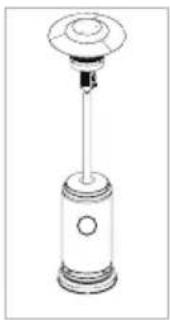
natural_image
Line drawing of a cylindrical mechanical device with a circular top and central shaft (no text or symbols)text_image
Diagram illustrating a mechanical assembly process with a wrench tool and warning symbol indicating failure or error.07
natural_image
Line drawing of a cylindrical industrial device with a circular top and base, no text or symbols present
text_image
max. 30 cm max. 60 cm GAS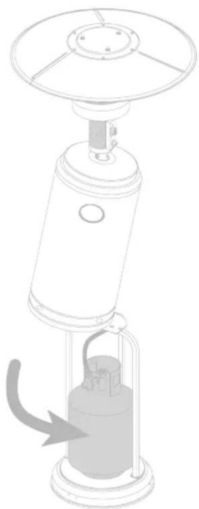
natural_image
Line drawing of a portable air conditioner unit with a cylindrical base and top control panel (no text or symbols)natural_image
Line drawing of a portable outdoor lighting fixture with a vertical pole and control panel (no text or symbols)
MAISON
Sonnenkönig of Switzerland
Olensbachstrasse 9-15
CH-9631 Ulisbach
Tel. Int. +41 58 611 60 00
Tel. Nat. 0848 870 850
Sonnenkönig of Switzerland
natural_image
Pure diagram of a curved road with directional arrows and rectangular components, no text or symbols present
natural_image
Technical line drawing of a mechanical device with two vertical supports and downward arrows indicating force or movement (no text or symbols)
natural_image
Line drawing of a cylindrical mechanical device with two protruding rods and a base plate (no text or symbols)02
N° Description Qté
7 Montant 1
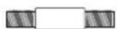
16 Vis M6 * 20 mm 6
11 Écrou M6 6
8 Réservoir 1

natural_image
Technical diagram of a mechanical assembly with multiple curved components and directional arrows indicating force or movement (no text or symbols present)
natural_image
Technical line drawing of a cylindrical mechanical component with a central hub and three vertical supports (no text or symbols)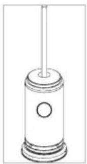
natural_image
Line drawing of a cylindrical mechanical component with a central hole and a vertical rod (no text or symbols)N° Description Qté
Tête de brûleur 1
14 Vis M6 * 10 mm 6
natural_image
Technical line drawing of a mechanical component with a pin and directional arrows indicating assembly or alignment (no text or symbols)
natural_image
Line drawing of a piston-cylinder engine with no text or symbols04
N° Description Qté
text_image
Diagram illustrating a mechanical or electrical system with concentric circular layers and directional arrows, showing component placement.
natural_image
Line drawing of a cylindrical mechanical device with a circular top and central shaft (no text or symbols)No Description Qty
Tube à gaz 1
text_image
Diagram illustrating a mechanical assembly process with a valve and wrench, showing a warning symbol and directional arrow.07
natural_image
Line drawing of a portable air conditioner with a circular top and base (no text or symbols)
text_image
max. 30 cm max. 60 cm GAS
natural_image
Technical line drawing of a portable air conditioner unit with a cooling tower and base mount (no text or symbols)05 - CONTRÔLE D'ÉTANCHÉITÉ
Table of the injector
Modifications techniques
natural_image
Line drawing of a portable outdoor lighting fixture with a vertical pole and control panel (no text or symbols)
DITTA
Sonnenkönig of Switzerland
Olensbachstrasse 9-15
CH-9631 Ulisbach
Tel. Int. +41 58 611 60 00
Tel. Nat. 0848 870 850
Sonnenkönig of Switzerland
natural_image
Pure diagram of a vehicle suspension system with no text, numbers, or symbols
natural_image
Technical line drawing of a mechanical device with two vertical supports and downward arrows indicating force or movement (no text or symbols)
natural_image
Line drawing of a cylindrical mechanical device with two protruding rods and a base plate (no text or symbols)02
N° Descrizione Qtà
7 Montante 1
16 Screw M6 * 20 mm 6
11 Nut M6 6
8 Serbatoio 1
natural_image
Technical diagram of a mechanical assembly with multiple curved components and directional arrows indicating force or movement (no text or symbols present)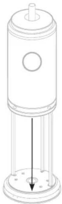
natural_image
Technical line drawing of a cylindrical mechanical component with a central hub and three vertical supports (no text or symbols)
natural_image
Line drawing of a cylindrical mechanical component with a central hole and a vertical rod (no text or symbols)N° Descrizione Qtà
natural_image
Technical diagram of a mechanical device with a central component and directional arrows indicating motion or force (no text or symbols present)
natural_image
Line drawing of a piston-cylinder engine (no text or symbols)04
N° Descrizione Qtà
text_image
Diagram illustrating a mechanical or electrical system with concentric circular layers and directional arrows, showing component placement.
natural_image
Line drawing of a piston-cylinder engine with no text or symbolsN° Descrizione Qtà
Tubo del gas 1
text_image
Diagram illustrating a mechanical assembly process with a valve and wrench, showing a warning symbol and directional arrow.07
natural_image
Line drawing of a portable air conditioner unit with a circular top and base, no text or symbols present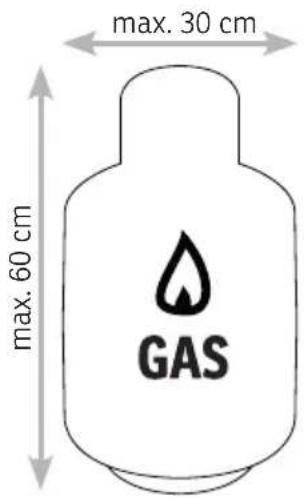
text_image
max. 30 cm max. 60 cm GAS
natural_image
Technical line drawing of a portable air conditioner unit with a cooling tower and base mount (no text or symbols)05 - CONTROLLO DELL'IMPERMEABILITÀ
natural_image
Line drawing of a portable outdoor lighting fixture with a vertical support structure and control panel (no text or symbols)
COMPANY
Sonnenkönig of Switzerland
Olensbachstrasse 9-15
CH-9631 Ulisbach
Tel. Int. +41 58 611 60 00
Tel. Nat. 0848 870 850
Sonnenkönig of Switzerland
Please read and understand this instruction manual completely before attempting to assemble, install and use the product!
This Manual contains critical information about the assembly, usage and maintenance of this device. General safety information is presented on these first pages and can also be found throughout the manual. Keep this manual for future reference and to educate new users of this product. This manual should be read in conjunction with the labeling on the product. Safety precautions are essential when using mechanical or propane powered equipment. These precautions are required when using, storing and maintaining this product. If this equipment is used with due respect and caution, the possibility of personal injury or damage to property will be reduced.
EXPLOSION - FIRE HAZARD
- Store fuels such as building materials, paper or cardboard, at a safe distance from the heater, as recommended in the instructions.
- Ensure sufficient clearance around the air openings in the combustion chamber.
- Never use the heater in rooms that contain or may contain volatile or airborne fuels or products such as gasoline, solvents, paint thinner, dust particles or unknown chemicals.
- During operation, this product may be a source of ignition. Keep the area around the heater free of combustible materials such as gasoline, thinner, cleaning solutions, and other flammable gases and liquids. Do not use the heater in areas with high dust generation. Minimum distance of the heater from flammable materials: three (3) feet to the side and two (2) feet from the top.
CARBON MONOXIDE - DANGER
- This heater is a combustion device. All combustion devices produce carbon monoxide (CO) during the combustion process. This product produces small, non-hazardous quantities of CO when used and maintained in accordance with all warnings and instructions. Care must be taken not to block the airflow to or from the heater.
- Carbon monoxide poisoning causes flu-like symptoms, watery eyes, headaches, dizziness, fatigue, and possibly death. You cannot see or smell carbon monoxide. If these symptoms occur during operation of this device, get fresh air immediately!
- For outdoor use only.
- Never use indoors or in other unventilated or enclosed spaces.
• This heater consumes air (oxygen).
DANGEROUS FUELS
- Never store propane near strong heat sources, naked flames, pilot lights, direct sunlight, other sources of ignition or at temperatures above 49°C.
- Propane gases are heavier than air and may accumulate in low locations. If you smell gas, leave the area immediately.
- Never install or remove propane cylinders while the heater is operating, near flames, pilot lights, other sources of ignition or when the heater is hot.
- This heater is highly incandescent during use and may ignite flammable materials near the burner. Keep flammable materials at least 90 cm from the sides and 60 cm from the top. Keep gasoline and other flammable liquids and gases away from the heater.
-
Store propane gas cylinders outdoors or in a well-ventilated room out of reach of children. Never store propane gas cylinders in a closed room (house, garage, etc.) If the heater is to be stored indoors, disconnect the propane gas cylinder for outdoor storage.
-
Do not store or use gasoline or other flammable gases and liquids near this or any other appliance. An unconnected gas cylinder must not be stored near this or any other device.
- This product is powered by propane gas. Propane gas is invisible, odorless and flammable.
Usually a so-called odorant is added to help detect leaks more easily and can be described as a "rotten egg" smell.
- The odorant volatilizes over time, so that escaping gas cannot always be detected by smell alone.
• Propane is heavier than air, and escaping propane sinks to the ground. - It can be ignited by ignition sources such as matches, lighters, sparks or open flames of all kinds, even if they are many meters away from the original leak.
- Only use propane gas that is designed to be vaporized.
RISK OF BURNS
- Never leave the heater unattended when it is hot or in operation.
- Keep out of the reach of children.
- Certain materials or objects, when stored under the heater, are exposed to radiant heat and could be seriously damaged.
SERVICE SECURITY
- Keep all connections and fittings clean. Make sure that the valve outlet of the propane cylinder is clean.
- During assembly, check all connections and fittings for leaks using soapy water. Never use a flame.
- Use only as a heater. Never modify in any way or use with any appliance.
- Warn children and adults of the dangers of high surface temperatures. Keep sufficient distance from these surfaces to avoid possible skin burns or the ignition of clothing.
• Always supervise small children when they are near the heater. - Do not hang clothes or other flammable materials on the heater or place them on or near the heater.
- Install any protective devices that have been removed for servicing the appliance before putting it back into operation.
- Installation and repair should only be performed by qualified service personnel. Have the heater professionally inspected before use and once a year.
- More frequent cleaning may be required if necessary.
- It is essential to ensure that the control housing, burner and circulating air duct of the appliance remain clean.
text_image
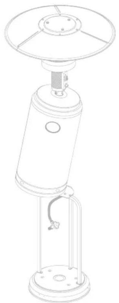
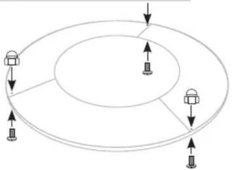
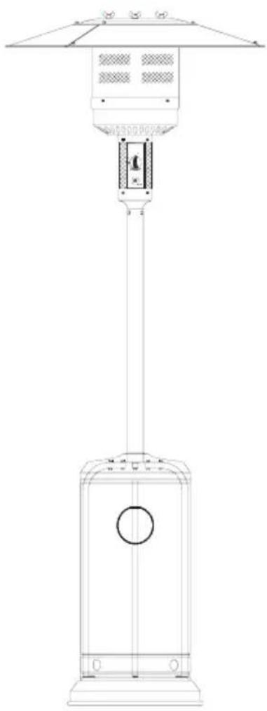
813 mm 2003 mm 2222 mm 765 mm 460 mm 10 8 9 7 1 2 3 4 5 6 1No Description Qty
1 Reflector panel 3
2 Flameguard 1
3 Burnerbase 1
4 Ventilation grille 1
5 Gas valve control 1
6 Base of controlhousing 1
7 Stand 1
8 Gastank housing 1
9 Mounting strut 3
10 Foot 1
11 Nut M6 15
12 Flanged nut M6 6
13 Wingnut 3
14 Screw M6 * 10 mm 15
15 Screw M8 * 15 mm 3
16 Screw M6 * 20 mm 6
17 Spacer 3
18 Washer M6 9
19 Washer M8 9
20 Protection hood 1

11

12 13

14 15 16

17

18 19
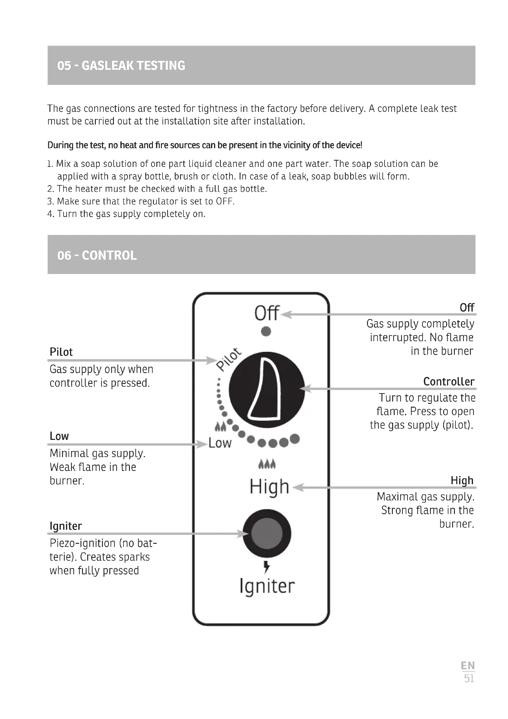
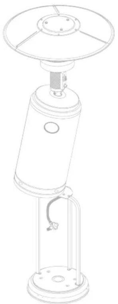
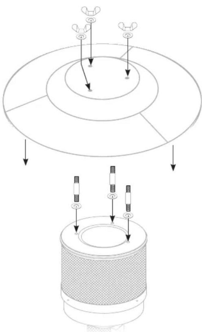
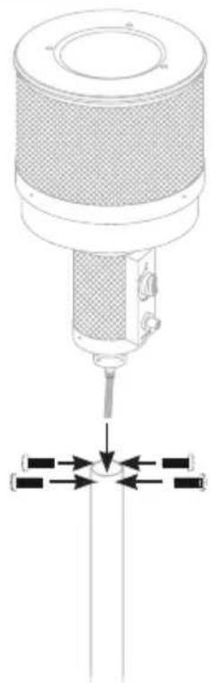
04 - ASSEMBLY
RESOURCES
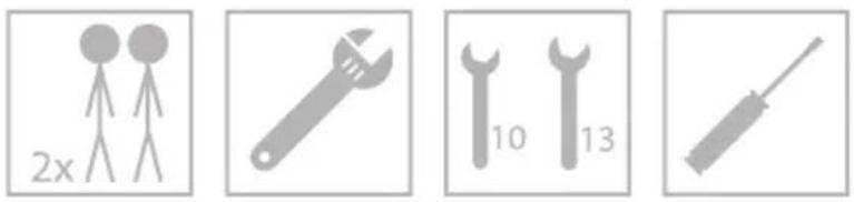
01
No Description Qty
6 Foot 1
9 Mounting strut 3
15 Screw M6 * 20 mm 3
natural_image
Pure diagram of a vehicle suspension system with no text, numbers, or symbols
natural_image
Technical line drawing of a mechanical device with two vertical supports and downward arrows indicating force or movement (no text or symbols)
natural_image
Line drawing of a cylindrical mechanical device with two protruding rods and a base plate (no text or symbols)02
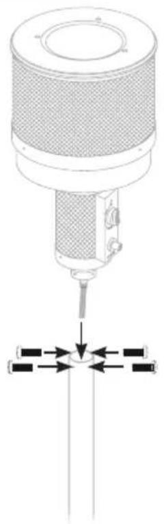
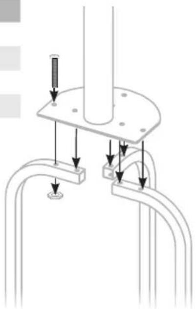
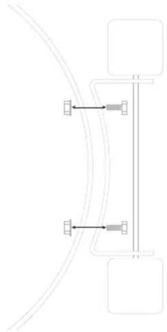
No Description Qty
7 Stand 1
16 Screw M6 * 20 mm 6
11 Nut M6 6
8 Tank housing 1

natural_image
Technical diagram of a mechanical assembly with multiple curved components and directional arrows indicating force or movement (no text or symbols present)
natural_image
Technical line drawing of a cylindrical mechanical component with a central hole and three vertical supports (no text or symbols)
natural_image
Line drawing of a cylindrical mechanical component with a central hole and a vertical rod (no text or symbols)No Description Qty
Burnerhead 1
14 Screw M6 * 10 mm 6

natural_image
Technical diagram of a mechanical device with a central component and directional arrows indicating motion or force (no text or symbols present)
natural_image
Line drawing of a piston-cylinder engine (no text or symbols)04
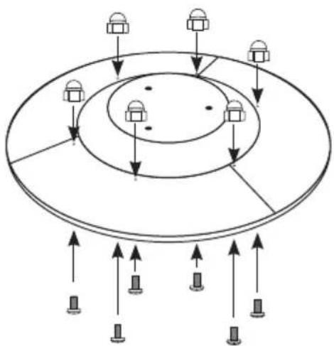
No Description Qty
1 Reflector panel 1
18 Wascher M8 6
13 Wing nut 3
17 Spacer 3
flowchart
graph TD
    A["Device 1"] --> B["Layer 1"]
    B --> C["Layer 2"]
    C --> D["Layer 3"]
    D --> E["Layer 4"]
    E --> F["Layer 5"]
    F --> G["Layer 6"]
    G --> H["Layer 7"]
    H --> I["Layer 8"]
    I --> J["Layer 9"]
    J --> K["Layer 10"]
    K --> L["Layer 11"]
    L --> M["Layer 12"]
    M --> N["Layer 13"]
    N --> O["Layer 14"]
    O --> P["Layer 15"]
    P --> Q["Layer 16"]
    Q --> R["Layer 17"]
    R --> S["Layer 18"]
    S --> T["Layer 19"]
    T --> U["Layer 20"]
    U --> V["Layer 21"]
    V --> W["Layer 22"]
    W --> X["Layer 23"]
    X --> Y["Layer 24"]
    Y --> Z["Layer 25"]

flowchart
graph TD
    A["Input Device 1"] --> B["Layer 1"]
    C["Input Device 2"] --> D["Layer 2"]
    E["Input Device 3"] --> F["Layer 3"]
    G["Input Device 4"] --> H["Layer 4"]
    I["Output Device 1"] --> J["Layer 1"]
    K["Output Device 2"] --> L["Layer 2"]
    M["Output Device 3"] --> N["Layer 3"]
    O["Output Device 4"] --> P["Layer 4"]
text_image
Diagram illustrating a mechanical or electrical system with concentric circular layers and directional arrows, showing component placement.
natural_image
Line drawing of a cylindrical mechanical device with a circular top and central shaft (no text or symbols)No Description Qty
Gastube 1
Pressure regulator 1
text_image
Diagram illustrating a mechanical assembly process with a valve and wrench, showing a warning symbol and directional arrow.07

natural_image
Line drawing of a portable air conditioner unit with a circular top and base, no text or symbols present
text_image
max. 30 cm max. 60 cm GAS
natural_image
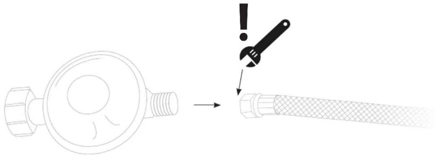
Line drawing of a portable air conditioner unit with a cooling tower and base mount (no text or symbols)The gas connections are tested for tightness in the factory before delivery. A complete leak test must be carried out at the installation site after installation.
During the test, no heat and fire sources can be present in the vicinity of the device!
- Mix a soap solution of one part liquid cleaner and one part water. The soap solution can be applied with a spray bottle, brush or cloth. In case of a leak, soap bubbles will form.
- The heater must be checked with a full gas bottle.
- Make sure that the regulator is set to OFF.
- Turn the gas supply completely on.
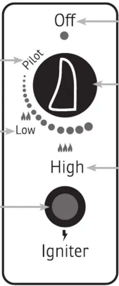
06 - CONTROL
Pilot
Gas supply only when controller is pressed.
Low
Minimal gas supply. Weak flame in the burner.
Igniter
Piezo-ignition (no batterie). Creates sparks when fully pressed
flowchart
graph TD
    A["Off"] --> B["Pilot"]
    B --> C["Low"]
    C --> D["High"]
    D --> E["Igniter"]
    style A fill:#000,stroke:#000,color:#fff
    style B fill:#000,stroke:#000,color:#fff
    style C fill:#000,stroke:#000,color:#fff
    style D fill:#000,stroke:#000,color:#fff
    style E fill:#000,stroke:#000,color:#fff
Off
Gas supply completely interrupted. No flame in the burner
Controller
Turn to regulate the flame. Press to open the gas supply (pilot).
High
Maximal gas supply. Strong flame in the burner.
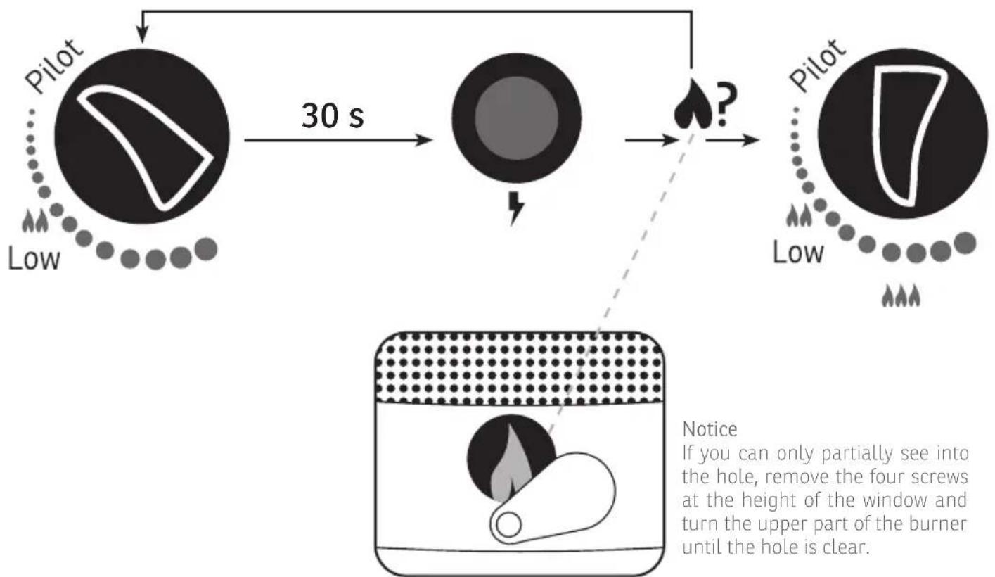
07 - STARTUP
Important: During initial start-up or after replacing a gas cylinder at step 2, wait at least 60 seconds to remove air from the lines.
- Open the valve of the gas cylinder completely.
- Press the gas control knob and turn it to the pilot position.
- Press and hold the gas control knob for 30 seconds and press the ignition button several times until the pilot light comes on. (The pilot flame can be checked through the small hole with sliding cover located on the bottom of the flame guard).
- Turn the gas control knob to the High position. Hold this setting for at least 5 minutes.
- Then turn the gas control knob to the desired heat output.
Turn off
- Turn the knob to the PILOT position.
- Press and turn the knob to the OFF position.
- Close the valve on the gas cylinder completely.
text_image
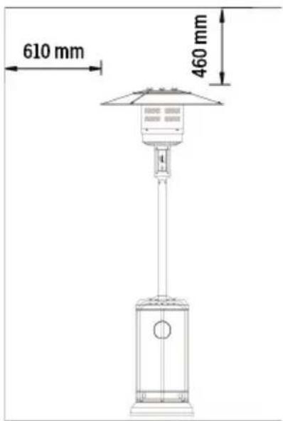
610 mm 460 mmMinimal safety distance
flowchart
graph TD
    A["Pilot"] -->|30 s| B["High"]
    B --> C{?}
    C -->|Yes| D["Pilot"]
    C -->|No| E["Low"]
    D --> F["Low"]
Any modifications or repairs to the device must be carried out by a qualified person.
Since the development of the produced devices is constantly progressing, your product may differ minimally from the one described.
08 - CLEANING, CARE AND MAINTENANCE
Storage
Before you store the device, make sure that the gasvalve is completely closed and the pressure regulator disconnected from the gastank. Only put the protection hood on, when device has cooled.
Cleaning
Clean coated surfaces with a soft, damp cloth. Never clean the heater with flammable or caustic cleaning agents. Make sure that the burner is cleaned regularly. Insects can get caught in the burner housing and burn during operation.
Maintenance
Perform a leak test after a longer period of non-use. If there is any damage to the technology, do not use the device and contact customer service.
09 - TECHNICAL DETAILS
Construction properties
- Transportable patio and garden heater with tank housing
- Housing made of steel with powder coating or stainless steel
- Gas hose connections with metal clamp (screw caps for Germany)
- Heat emission reflector
Technical properties
- Only use propane or butane gas
• Max.Wattage:13kW - Min Wattage: 5 kW
Table of the injector
| Gas category | 3+ (28 - 30/37) | 3B/P(30) | 3 B/P (50) | 3B/P(37) | |
| Gas-Types Butane Propane | LPGGasmixture | LPGGasmixture | LPGGasmixture | ||
| Gas pressure | 28 - 30 mbar | 37 mbar | 30 mbar | 50 mbar | 37 mbar |
| Total heat input:(HS): (QN) | 13 kW (Butan: 945 g/h • Propan: 928 g/h) | ||||
| Injector Size | |||||
| 1.88 mm to Mainburner0.18 mm to Pilorburner | 1.55 mm to Mainburner0.18 mm to Pilorburner | 1.65 mm to Mainburner0.18 mm to Pilorburner | |||
| The mark on the injector (e.g. 1.88) indicates that the size of the injector is 1.88 mm | |||||
Warranty
All products are checked from our company before the delivery. In case that there is a lack on your product, please contact the vendor. Please bring your proof of purchase for guarantees. Please save the packaging materials of the unit.
Disposal
Please remove the heater properly. You can bring the product to any specialist dealer fort he removal.
Technical changes
Technical changes in technique and design are possible.
CE declaration of Conformity
This device complies with the following standards
EWR EN 14543:2017
EWR 2016/426
DISPOSAL INSTRUCTIONS FOR THE ELECTRICAL PART OF THE PRODUCT
In accordance with Article 26 of the Decree-Law of 14 March 2014 implementing Directive 2012/19/EC, and the Law of 31 March 2015 implementing Directive 2015/863/EU on the reduction of the use of hazardous substances in electrical and electronic equipment and on waste management.
The crossed-out dustbin symbol on the machine or packaging indicates that the waste generated at the end of its useful life must be collected separately from other waste. The user must therefore take the device to the appropriate collection points at the end of its service life. Sort electronic and electrical waste or send back to the retailer when purchasing new, equivalent devices in a one-to-one process. Appropriate separate collection for subsequent commissioning of the equipment to be recycled, treatment and environmentally sound disposal helps to avoid possible adverse effects on the environment and health, and promote the reuse and/or recycling of the materials to which they belong. Misuse of this product by the user will result in the application of the administrative penalties provided for in the applicable legislation. Batteries contained in the device must be disposed of separately in the appropriate containers for the collection of used batteries.
DISPOSAL OF BATTERIES AND ACCUMULATORS
In accordance with Legislative Decree 188 of 20 November 2008 implementing Directive 2006/66/EC on batteries, accumulators and related waste, the sym-
bol of the crossed-out waste bin on the battery indicates that the disposal of used batteries is prohibited in household waste.
Single-use and rechargeable batteries contain substances that are highly polluting for the environment. The user is obliged to dispose of used batteries at collection points in the municipality or in appropriate containers. This service is free. In this way, legal requirements are adhered to and the environment protected. The symbols identifying hazardous materials that may be present in single-use and rechargeable batteries are as follows: Hg = Mercury, Cd = Cadmium, Pb = Lead.
WÄRMEPILZ CHROM GAS
TERRASVERWARMING
natural_image
Line drawing of a portable outdoor lighting fixture with a vertical support structure and control panel (no text or symbols)
BEDRIJF
Sonnenkönig of Switzerland
Olensbachstrasse 9-15
CH-9631 Ulisbach
Tel. Int. +41 58 611 60 00
Tel. Nat. 0848 870 850
Sonnenkönig of Switzerland
natural_image
Pure diagram of a curved road with directional arrows and rectangular blocks, no text or symbols present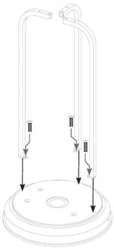
natural_image
Technical line drawing of a mechanical device with two vertical supports and downward arrows indicating force or movement (no text or symbols)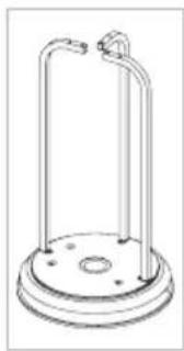
natural_image
Line drawing of a cylindrical mechanical device with a base and mounting feet (no text or symbols)02
Nr Omschrijving Qty
7 Voet 1
16 Schroef M6 * 20 mm 6
11 Moer M6 6
8 Gastank huis 1

natural_image
Technical diagram of a mechanical assembly with multiple curved components and directional arrows indicating force or movement (no text or symbols present)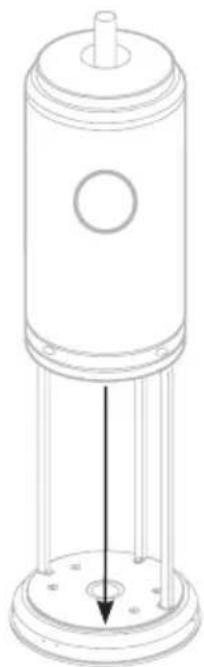
natural_image
Technical line drawing of a cylindrical mechanical component with a central hole and three vertical supports (no text or symbols)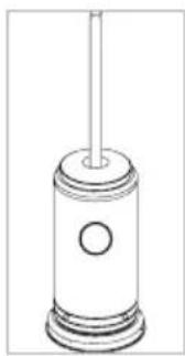
natural_image
Line drawing of a piston-cylinder assembly with no text or symbolsNr Omschrijving Qty
Brander 1
14 Schroef M6 * 10 mm 6
natural_image
Technical diagram of a mechanical device with a central component and directional arrows indicating motion or force (no text or symbols present)
natural_image
Line drawing of a piston-cylinder engine (no text or symbols)04
Nr Omschrijving Qty
1 Reflectorpaneel 1
18 Wascher M8 6
13 Vleugelmoer 3
17 Afstandsbus 3

flowchart
graph TD
    A["Device 1"] --> B["Layer 1"]
    B --> C["Layer 2"]
    C --> D["Layer 3"]
    D --> E["Layer 4"]
    E --> F["Layer 5"]
    F --> G["Layer 6"]
    G --> H["Layer 7"]
    H --> I["Layer 8"]
    I --> J["Layer 9"]
    J --> K["Layer 10"]
    K --> L["Layer 11"]
    L --> M["Layer 12"]
    M --> N["Layer 13"]
    N --> O["Layer 14"]
    O --> P["Layer 15"]
    P --> Q["Layer 16"]
    Q --> R["Layer 17"]
    R --> S["Layer 18"]
    S --> T["Layer 19"]
    T --> U["Layer 20"]
    U --> V["Layer 21"]
    V --> W["Layer 22"]
    W --> X["Layer 23"]
    X --> Y["Layer 24"]
    Y --> Z["Layer 25"]
flowchart
graph TD
    A["Input Device 1"] --> B["Layer 1"]
    C["Input Device 2"] --> D["Layer 2"]
    E["Input Device 3"] --> F["Layer 3"]
    G["Input Device 4"] --> H["Layer 4"]
    I["Output Device 1"] --> J["Layer 1"]
    K["Output Device 2"] --> L["Layer 2"]
    M["Output Device 3"] --> N["Layer 3"]
    O["Output Device 4"] --> P["Layer 4"]

text_image
Diagram illustrating a mechanical or electrical system with concentric circular layers and directional arrows, showing component placement.
natural_image
Line drawing of a cylindrical mechanical device with a circular top and central shaft (no text or symbols)Nr Omschrijving Qty
Gastube 1
Drukregelaar 1

text_image
Diagram illustrating a mechanical assembly process with a valve and wrench, showing a warning symbol and directional arrow.07

natural_image
Line drawing of a portable air conditioner unit with a circular top and base, no text or symbols present
text_image
max. 30 cm max. 60 cm GAS