366013 - Saw DELTA - Free user manual and instructions
Find the device manual for free 366013 DELTA in PDF.
| Product Type | Table Saw |
| Brand | Delta |
| Model | 366013 |
| Power Supply | 120 V, 15 A, 60 Hz, AC |
| No-load Speed | 5,000 RPM |
| Blade Diameter | 10 inches (254 mm) |
| Max Cutting Depth at 90° | 3 1/2 inches (89 mm) |
| Max Cutting Depth at 45° | 2 1/2 inches (63.5 mm) |
| Rip Capacity to the Right | 25 inches (635 mm) |
| Rip Capacity to the Left | 12 inches (305 mm) |
| Main Functions | Crosscut, rip cut, bevel cut (0° to 45°), dado and rabbet (with accessories) |
| Safety Equipment | Transparent blade guard, adjustable riving knife, anti-kickback pawls, lockable switch |
| Included Accessories | Rip fence, miter gauge with T-slot, push stick, 10-inch carbide blade, throat plate, assembly wrenches |
| Maintenance | Regularly clean the air vents and cutting area; grease the bevel gears with lithium-based grease; use compressed air for dust removal |
| Repairability | Replacement parts available through the Delta authorized service center network; power cord replacement by a professional only |
| Warranty | 5-year limited warranty (parts and labor) for domestic use in the United States and Canada |
Frequently Asked Questions - 366013 DELTA
User questions about 366013 DELTA
0 question about this device. Answer the ones you know or ask your own.
Ask a new question about this device
Download the instructions for your Saw in PDF format for free! Find your manual 366013 - DELTA and take your electronic device back in hand. On this page are published all the documents necessary for the use of your device. 366013 by DELTA.
USER MANUAL 366013 DELTA
IMPORTANT SAFETY INSTRUCTIONS 4
SAFETY SYMBOLS-DEFINITIONS 4
GENERAL POWER TOOL SAFETY WARNINGS 5
TABLE SAW SAFETY RULES 6
TERMINOLOGY 6
TABLE SAW SPECIFIC SAFETY RULES. 6
SAW BLADE GUARD, ANTI-KICKBACK PAWLS AND RIVING
KNIFE ASSEMBLY 8
KICKBACKS 8
PROPOSITION 65 WARNING .8
POWER CONNECTIONS 9
POWER SOURCE. 9
DOUBLE INSULATION 9
ELECTRICAL CONNECTION. 9
POLARIZED PLUGS 9
EXTENSION CORDS 9
UNPACKING. 10
PACKAGE CONTENTS 10
HARDWARE BAG CONTENTS 11
ASSEMBLY 12
TOOLS NEEDED FOR ASSEMBLY OR ADJUSTMENTS 12
ASSEMBLING THE STAND. 13
ATTACHING STAND TO SAW 14
HEIGHT ADJUSTMENT KNOB INSTALLATION 15
INSTALLING THE BLADE 15
THROAT PLATE. 16
ANTI-KICKBACKS PAWLS AND BLADE GUARD 17
INSTALLING FENCE 18
REMOVING FENCE 18
ON-BOARD STORAGE. 19
MAKING ADJUSTMENTS 20
LEVELING THE THroat PLATE 20
ADJUSTING BLADE PARALLEL TO MITER GAUGE GROOVE (HEEL) 20
SQUARING THE BLADE VERTICALLY 21
ADJUSTING THE BEVEL STOPS 22
RIVING KNIFE HEIGHT SETTING 26
PARALLEL ALIGNMENT 27
HORIZONTAL ALIGNMENT 27
VERTICAL ALIGNMENT 27
OPERATION 28
DUST COLLECTION 29
TURING THE SAW ON AND OFF 29
TRANSPORTING THE SAW. 29
MAKING CUTS 30
RIP CUTS.
BEVEL RIPING 31
CROSScutting. 32
BEVEL CROSScutTING 32
MITER CUTS 32
COMPOUND MITER CUTS. 33
LARGE PANEL CUTS. 33
NON-THROUGH CUTS 33
MAKING A NON-THROUGH CUT 33
CUTTING AIDS AND ACCESSORIES 34
PUSH STICK 34
USING THE MITER GAUGE 34
AUXILIARY MITER GAUGE FACING. 35
AUXILIARY FENCE (FLIP DOWN). 35
PUSH BLOCK 35
GROOVING AND RABBETING 35
FEATHERBOARD 36
CUT OFF GAUGE 36
JIGS. 36
MAINTENANCE 37
KEEP MACHINE CLEAN. 37
MAINTENANCE REMINDERS 37
ACCESSIONS 38
TROUBLESHOOTING 38
PARTS, SERVICE OR WARRANTY ASSISTANCE. 39
FEATURES
SPECIFICATIONS
| Max depth of cut at 90 degrees: 3 1/2 inch | |
| Max depth of cut at 45 degrees: | 2 1/2 inch |
| Max rip to right of blade: | 25 inch |
| Max rip to left of blade: | 12 inch |
| MOTOR SPECIFICATIONS: | |
| Amps | 15 |
| Voltage | 120 |
| No Load RPM 5,000 | |
| Blade Diameter 10 inch | |
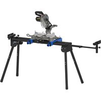
The DELTA® 36-6013 series 10 inch Portable Contractor Table Saw is designed for portability and high quality performance. It includes: basic machine, sturdy tubular steel stand, integral 2 1/2 inch dust chute, a fence system, T-slot miter gauge, 15-amp motor, on/off switch, cast aluminum table, extension wing, see-through blade guard with anti-kickback pawls, and 10 inch carbide blade.
This tool can ONLY be used with woodworking saw blades.
NOTICE: The manual cover illustrates the current production model. All other illustrations contained in the manual are representative ONLY and may not be exact depictions of the actual labeling or accessories included. They are intended for illustrative purposes ONLY.
FEATURES
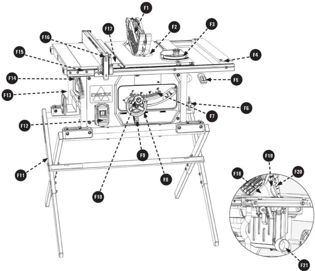
F1 Blade Guard
F2 Throat Plate
F3 Miter Gauge
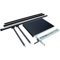
F4 Extension Wing
F5 Extension Lock
F6 On Board Storage
F7 Bevel Scale
F8 Height Adjustment Handwheel
F9 Bevel Lock Lever
F10 Height Adjustment Knob
F11 Stand (36-6013 X Only)
F12 On/Off Switch
F13 Saw Body
F14 Push Stick
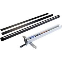
F15 Fence Rails
F16 Rip Fence
F17 Flip Down Fence
F18 Saw Blade
F19 Anti-Kickback Pawls
F20 Riving Knife
F21 Dust Chute
IMPORTANT SAFETY INSTRUCTIONS
WARNING:
CAREFULLY READ AND FOLLOW ALL WARNINGS AND INSTRUCTIONS ON YOUR PRODUCT AND IN THIS MANUAL. SAVE THIS MANUAL. MAKE SURE ALL USERS ARE FAMILIAR WITH ITS

WARNING AND INSTRUCTIONS WHEN USING THE TOOL. Improper operation, maintenance or modification of tools or equipment could result in serious injury and/or property damage. KEEP this manual near your saw for easy reference and to instruct others.
If you have any questions or concerns relative to the use of your tool or the contents of this manual, stop using the tool and contact Delta Power Equipment Corporation Customer Care at 1-800-223-7278.
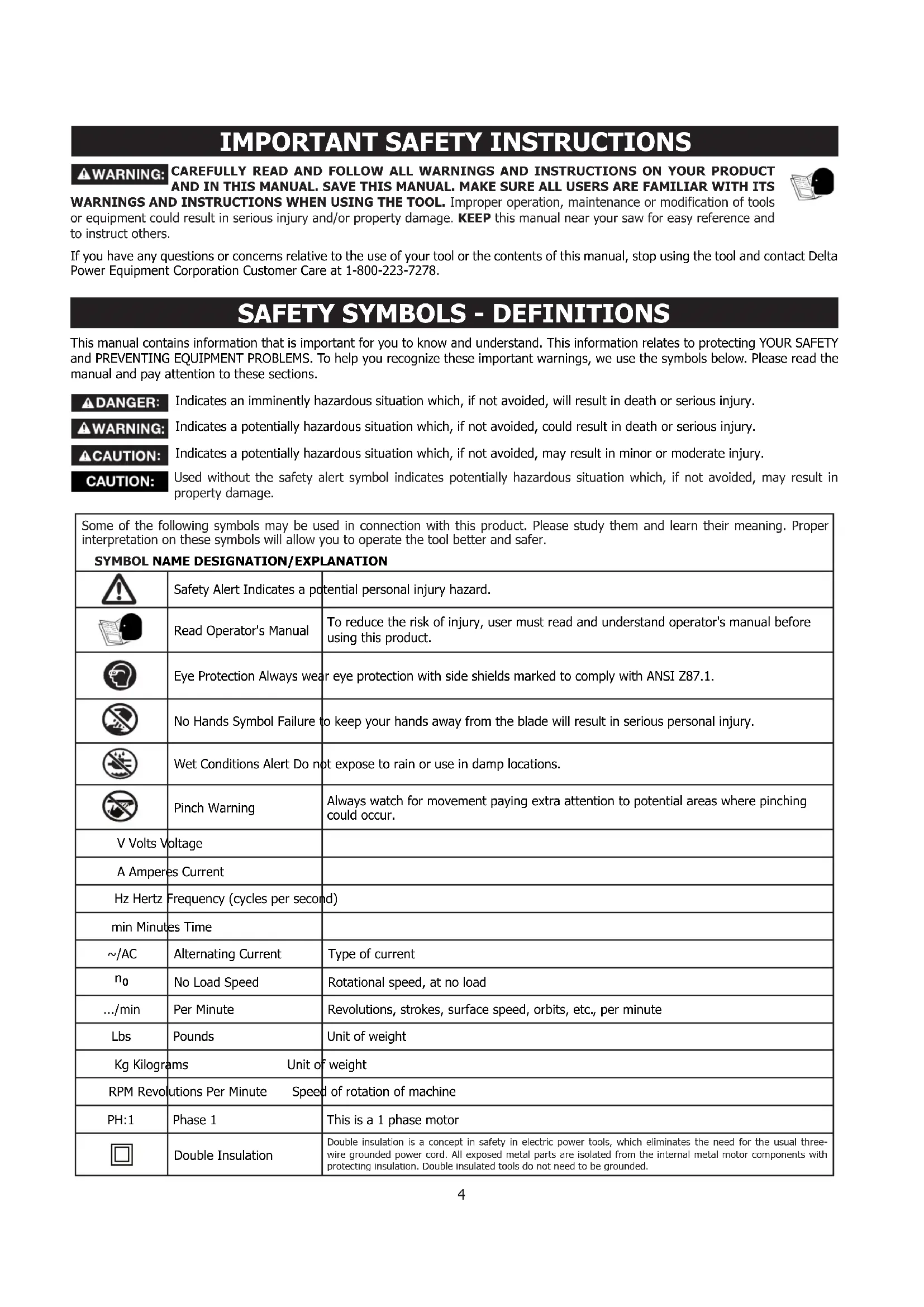
SAFETY SYMBOLS - DEFINITIONS
This manual contains information that is important for you to know and understand. This information relates to protecting YOUR SAFETY and PREVENTING EQUIPMENT PROBLEMS. To help you recognize these important warnings, we use the symbols below. Please read the manual and pay attention to these sections.
DANGER:
Indicates an imminently hazardous situation which, if not avoided, will result in death or serious injury.
WARNING:
Indicates a potentially hazardous situation which, if not avoided, could result in death or serious injury.
CAUTION:
Indicates a potentially hazardous situation which, if not avoided, may result in minor or moderate injury.
CAUTION:
Used without the safety alert symbol indicates potentially hazardous situation which, if not avoided, may result in property damage.
| Some of the following symbols may be used in connection with this product. Please study them and learn their meaning. Proper interpretation on these symbols will allow you to operate the tool better and safer. SYMBOL NAME DESIGNATION/EXPLANATION | ||
| Safety Alert Indicates a potential personal injury hazard. | ||
| Read Operator's Manual | To reduce the risk of injury, user must read and understand operator's manual before using this product. | |
| Eye Protection Always wear eye protection with side shields marked to comply with ANSI Z87.1. | ||
| No Hands Symbol Failure to keep your hands away from the blade will result in serious personal injury. | ||
| Wet Conditions Alert Do not expose to rain or use in damp locations. | ||
| Pinch Warning | Always watch for movement paying extra attention to potential areas where pinching could occur. | |
| V Volts Voltage | ||
| A Amperes Current | ||
| Hz Hertz Frequency (cycles per second) | ||
| min Minutes Time | ||
| ~/AC | Alternating Current | Type of current |
| n0 | No Load Speed | Rotational speed, at no load |
| .../min | Per Minute | Revolutions, strokes, surface speed, orbits, etc., per minute |
| Lbs | Pounds | Unit of weight |
| Kg Kilograms Unit of weight | ||
| RPM Revolutions Per Minute Speed of rotation of machine | ||
| PH:1 | Phase 1 | This is a 1 phase motor |
| Double Insulation | Double insulation is a concept in safety in electric power tools, which eliminates the need for the usual three-wire grounded power cord. All exposed metal parts are isolated from the internal metal motor components with protecting insulation. Double insulated tools do not need to be grounded. | |
GENERAL POWER TOOL SAFETY WARNINGS
WARNING:
Read all safety warnings, instructions, illustrations and specifications provided with this power tool. Failure to follow all instructions listed below may result in electric shock, fire and/or serious injury.
Save all warnings and instructions for future reference.
The term "power tool" in the warnings refers to your mains-operated (cored) power tool or BATTERY-operated (cordless) power tool.
1. Work area safety
a. Keep work area clean and well-lit. Cluttered or dark areas invite accidents.
b. Do not operate power tools in explosive atmospheres, such as in the presence of flammable liquids, gases or dust. Power tools create sparks which may ignite the dust or fumes.
c. Keep children and bystanders away while operating a power tool. Distractions can cause you to lose control.
2. Electrical safety
a. Power tool plugs must match the outlet. Never modify the plug in any way. Do not use any adapter with earthed (grounded) power tools. Unmodified plugs and matching outlets will reduce risk of electric shock.
b. Avoid body contact with earthed or grounded surfaces, such as pipes, radiators, ranges and refrigerators. There is an increased risk of electric shock if your body is earthed or grounded.
c. Do not expose power tools to rain or wet conditions. Water entering a power tool will increase the risk of electric shock.
d. Do not abuse the cord. Never use the cord for carrying, pulling or unplugging the power tool. Keep cord away from heat, oil, sharp edges or moving parts. Damaged or entangled cords increase the risk of electric shock.
e. When operating a power tool outdoors, use an extension cord suitable for outdoor use. Use of a cord suitable for outdoor use reduces the risk of electric shock.
f. If operating a power tool in a damp location is unavoidable, use a ground fault circuit interrupter (GFCI) protected supply. Use of an GFCI reduces the risk of electric shock.
3. Personal safety
a. Stay alert, watch what you are doing and use common sense when operating a power tool. Do not use a power tool while you are tired or under the influence of drugs, alcohol or medication. A moment of inattention while operating power tools may result in serious personal injury.
b. Use personal protective equipment. Always wear eye protection. Protective equipment such as dust mask, non-skiid safety shoes, hard hat, or hearing protection used for appropriate conditions will reduce personal injuries.
c. Prevent unintentional starting. Ensure the switch is in the off-position before connection to power source, picking up, or carrying the tool. Carrying power tools with your finger on the switch or energising power tools that have the switch on invites accidents.
d. Remove any adjusting key or wrench before turning the power tool on. A wrench or a key left attached to a rotating part of the power tool may result in personal injury.
e. Do not overreach. Keep proper footing and balance at all times. This enables better control of the power tool in unexpected situations.
f. Dress properly. Do not wear loose clothing or jewelry. Keep your hair, clothing and gloves away from moving parts. Loose clothes, jewelry or long hair can be caught in moving parts.
g. If devices are provided for the connection of dust extraction and collection facilities, ensure these are connected and properly used. Use of dust collection can reduce dust-related hazards.
h. Do not let familiarity gained from frequent use of tools allow you to become complacent and ignore tool safety principles. A careless action can cause severe injury within a fraction of a second.
4. Power tool use and care
a. Do not force the power tool. Use the correct power tool for your application. The correct power tool will do the job better and safer at the rate for which it was designed.
b. Do not use the power tool if the switch does not turn it on and off. Any power tool that cannot be controlled with the switch is dangerous and must be repaired.
c. Disconnect the plug from the power source before making any adjustments, changing accessories, or storing power tools. Such preventive safety measures reduce the risk of starting the power tool accidentally.
d. Store idle power tools out of the reach of children and do not allow persons unfamiliar with the power tool or these instructions to operate the power tool. Power tools are dangerous in the hands of untrained users.
e. Maintain power tools and accessories. Check for misalignment or binding of moving parts, breakage of parts and any other condition that may affect the power tool's operation. If damaged, have the power tool repaired before use. Many accidents are caused by poorly maintained power tools.
f. Keep cutting tools sharp and clean. Properly maintained cutting tools with sharp cutting edges are less likely to bind and are easier to control.
g. Use the power tool, accessories and tools bits etc. in accordance with these instructions, taking into account the working conditions and the work to be performed. Use of the power tool for operations different from those intended could result in a hazardous situation.
h. Keep handles and grasping surfaces dry, clean and free from oil and grease. Slippery handles and grasping surfaces do not allow for safe handling and control of the tool in unexpected situations.
5. Service
a. Have your power tool serviced by a qualified repair person using only identical replacement parts. This will ensure that the safety of the power tool is maintained.

TABLE SAW SAFETY RULES
WARNING: Failure to follow these rules may result in serious personal injury.
SEE GENERAL POWER TOOL SAFETY SECTION OF THIS MANUAL. Read entire instruction manual before operating saw. Learning the saw's proper applications, limitations, and specific potential hazards will greatly minimize the possibility of accidents and injury. Make sure all users are familiar with its warnings and instructions before using saw.
SEE POWER CONNECTION SECTION OF THIS MANUAL for instructions and warnings regarding power cords and connections.
TERMINOLOGY
The following terms will be used throughout the manual and you should become familiar with them.
- Through-cut - Any cut that completely cuts through the workpiece.
- Non-through cut - Any cut that does not completely cut through the workpiece.
- Push stick - A wooden or plastic stick, usually homemade, that is used to push a small workpiece through the saw and keeps the operator's hands clear of the blade.
- Kickback - Occurs when the saw blade binds in the cut or between the blade and the fence and thrusts the workpiece back toward the operator.
- Re-sawing - Flipping material to make a cut the saw is not capable of making in one pass.
- Cove cutting - Also known as caving, cove cutting is an operation where the work is fed at an angle across the
blade. NOTE: This can be a dangerous operation and is not recommended.
Freehand - Cutting without the use of a miter gauge or rip fence or any other means of guiding or holding the workpiece other than the operator's hand. NOTE: This can be a dangerous operation and is not recommended.
- Plunge cutting - Blind cuts in the workpiece made by raising the blade through the workpiece or lowering the workpiece down to the blade. NOTE: This can be a dangerous operation and is not recommended.
- Rabbit Cut - A cut on the end face (edge) of a board for the purpose of joining two boards. The protruding edge is called the tongue and the recessed edge is called the groove.
- Kerf - A cut or incision made by a saw.
TABLE SAW SPECIFIC SAFETY RULES

WARNING READ ALL SAFETY WARNINGS DESIGNATED BY THE SYMBOL AND ALL INSTRUCTIONS.
WARNING: Failure to follow these rules may result in serious personal injury.
1. GUARDING RELATED WARNINGS
a. Keep guards in place. Guards must be in working order and be properly mounted. A guard that is loose, damaged, or is not functioning correctly must be repaired or replaced.
b. Always use saw blade guard, riving knife and anti-kickback device for every through-cutting operation. For through-cutting operations where the saw blade cuts completely through the thickness of the workpiece, the guard and other safety devices help reduce the risk of injury.
c. Immediately reattach the guarding system after completing an operation (such as rabbeting or resawing cuts) which requires removal of the guard, riving knife and/or anti-kickback device. The guard, riving knife, and anti-kickback device help to reduce the risk of injury.
d. Make sure the saw blade is not contacting the guard, riving knife or the workpiece before the switch is turned on. Inadvertent contact of these items with the saw blade could cause a hazardous condition.
e. Adjust the riving knife as described in this instruction manual. Incorrect spacing, positioning and alignment can make the riving knife ineffective in reducing the likelihood of kickback.
f. For the riving knife and anti-kickback device to work, they must be engaged in the workpiece. The riving knife and anti-kickback device are ineffective when cutting workpieces that are too short to be engaged with the riving knife and anti-kickback device. Under these conditions a kickback cannot be prevented by the riving knife and antikickback device.
g. Use the appropriate saw blade for the riving knife. For the riving knife to function properly, the saw blade diameter must match the appropriate riving knife and the body of the saw blade must be thinner than the thickness of the riving knife and the cutting width of the saw blade must be wider than the thickness of the riving knife.
2. CUTTING PROCEDURES \*WARNINGS
a. DANGER: Never place your fingers or hands in the vicinity or in line with the saw blade. A moment of inattention or a slip could direct your hand towards the saw blade and result in serious personal injury.
b. Feed the workpiece into the saw blade or cutter only against the direction of rotation. Feeding the workpiece in the same direction that the saw blade is rotating above the table may result in the workpiece, and your hand, being pulled into the saw blade.
c. Never use the mitre gauge to feed the workpiece when ripping and do not use the rip fence as a length stop when cross cutting with the mitre gauge. Guiding the workpiece with the rip fence and the miter gauge at the same time increases the likelihood of saw blade binding and kickback.
d. When ripping, always apply the workpiece feeding force between the fence and the saw blade. Use a push stick when the distance between the fence and the saw blade is less than 50mm , and use a push block when this distance is less than 150mm . "Work helping" devices will keep your hand at a safe distance from the saw blade.
e. Use only the push stick provided by the manufacturer or constructed in accordance with the instructions. This push stick provides sufficient distance of the hand from the saw blade.
f. Never use a damaged or cut push stick. A damaged push stick may break causing your hand to slip into the saw blade.
g. Do not perform any operation "freehand". Always use either the rip fence or the litre gauge to position and guide the workpiece. "Freehand" means using your hands to support or guide the workpiece, in lieu of a rip fence or miter gauge. Freehand sawing leads to misalignment, binding and kickback.
h. Never reach around or over a rotating saw blade. Reaching for a workpiece may lead to accidental contact with the moving saw blade.
TABLE SAW SAFETY RULES
i. Provide auxiliary workpiece support to the rear and/or sides of the saw table for long and/or wide workpieces to keep them level. A long and/or wide workpiece has a tendency to pivot on the table's edge, causing loss of control, saw blade binding and kickback.
j. Feed workpiece at an even pace. Do not bend or twist the workpiece. If jamming occurs, turn the tool off immediately, unplug the tool then clear the jam. Jamming the saw blade by the workpiece can cause kickback or stall the motor.
k. Do not remove pieces of cut-off material while the saw is running. The material may become trapped between the fence or inside the saw blade guard and the saw blade pulling your fingers into the saw blade. Turn the saw off and wait until the saw blade stops before removing material.
1. Use an auxiliary fence in contact with the table top when ripping workpieces less than 2mm thick. A thin workpiece may wedge under the rip fence and create a kickback.
m. Never Cut Metals, Cement Board or Masonry. Certain man-made materials have special instructions for cutting on table saws. Follow the manufacturer's recommendations at all times to avoid overheating the saw blade tips as well as melting the plastic. Avoid overheating blade tips by pushing material through blade evenly. Forcing material too fast can cause overheating and damage to blade or workpiece. If cutting plastics is permitted, cut at a slower pace to avoid melting the plastic.
3. Kickback causes and related warnings
Kickback is a sudden reaction of the workpiece due to a pinched, jammed saw blade or misaligned line of cut in the workpiece with respect to the saw blade or when a part of the workpiece binds between the saw blade and the rip fence or other fixed object.
a. Most frequently during kickback, the workpiece is lifted from the table by the rear portion of the saw blade and is propelled towards the operator. Kickback is the result of saw misuse and/or incorrect operating procedures or conditions and can be avoided by taking proper precautions as given below.
b. Never stand directly in line with the saw blade. Always position your body on the same side of the saw blade as the fence. Kickback may propel the workpiece at high velocity towards anyone standing in front and in line with the saw blade.
c. Never reach over or in back of the saw blade to pull or to support the workpiece. Accidental contact with the saw blade may occur or kickback may drag your fingers into the saw blade.
d. Never hold and press the workpiece that is being cut off against the rotating saw blade. Pressing the workpiece being cut off against the saw blade will create a binding condition and kickback.
e. Align the fence to be parallel with the saw blade. A misaligned fence will pinch the workpiece against the saw blade and create kickback.
f. Use a featherboard to guide the workpiece against the table and fence when making non-through cuts such as rabbeting, or resawing cuts. A featherboard helps to control the workpiece in the event of a kickback.
g. Use extra caution when making a cut into blind areas of assembled workpieces. The protruding saw blade may cut objects that can cause kickback.
h. Support large panels to minimise the risk of saw blade pinching and kickback. Large panels tend to sag under their own weight. Support(s) must be placed under all portions of the panel overhanging the table top.
i. Use extra caution when cutting a workpiece that is twisted, knotted, warped or does not have a straight edge to guide it with a litre gauge or along the fence. A warped, knotted, or twisted workpiece is unstable and causes misalignment of the kerf with the saw blade, binding and kickback.
j. Never cut more than one workpiece, stacked vertically or horizontally. The saw blade could pick up one or more pieces and cause kickback.
k. When restarting the saw with the saw blade in the workpiece, centre the saw blade in the kerf so that the saw teeth are not engaged in the material. If the saw blade binds, it may lift up the workpiece and cause kickback when the saw is restarted.
1. Keep saw blades clean, sharp, and with sufficient set. Never use warped saw blades or saw blades with cracked or broken teeth. Sharp and properly set saw blades minimize binding, stalling and kickback.
4. Table saw operating procedure warnings
a. Turn off the table saw and disconnect the power cord when removing the table insert, changing the saw blade or making adjustments to the riving knife, anti-kickback device or saw blade guard, and when the machine is left unattended. Precautionary measures will avoid accidents.
b. Never leave the table saw running unattended. Turn it off and don't leave the tool until it comes to a complete stop. An unattended running saw is an uncontrolled hazard.
c. Locate the table saw in a well-lit and level area where you can maintain good footing and balance. It should be installed in an area that provides enough room to easily handle the size of your workpiece. Cramped, dark areas, and uneven slippery floors invite accidents.
d. Frequently clean and remove sawdust from under the saw table and/or the dust collection device. Accumulated sawdust is combustible and may self-ignite.
e. The table saw must be secured. A table saw that is not properly secured may move or tip over.
f. Remove tools, wood scraps, etc. from the table before the table saw is turned on. Distraction or a potential jam can be dangerous.
g. Always use saw blades with correct size and shape (diamond versus round) of arbor holes. Saw blades that do not match the mounting hardware of the saw will run off-center, causing loss of control.
h. Never use damaged or incorrect saw blade mounting means such as flanges, saw blade washers, bolts or nuts. These mounting means were specially designed for your saw, for safe operation and optimum performance.
i. Never stand on the table saw, do not use it as a stepping stool. Serious injury could occur if the tool is tipped or if the cutting tool is accidentally contacted.
j. Make sure that the saw blade is installed to rotate in the proper direction. Do not use grinding wheels, wire brushes, or abrasive wheels on a table saw. Improper saw blade installation or use of accessories not recommended may cause serious injury.
k. DO NOT REMOVE A WORKPIECE that is damaged or jammed without first turning off the saw and unplugging it from the power source.
TABLE SAW SAFETY RULES
SAW BLADE GUARD, ANTI-KICKBACK PAWLS AND RIVING KNIFE ASSEMBLY
Your Table Saw is equipped with a Blade Guard, Anti-Kickback Pawls and Riving Knife Assembly that covers the Blade and reduces the possibility of accidental Blade contact.
The Riving Knife is a flat plate that fits into the cut made by the Saw Blade and effectively fights kickback by lessening the tendency of the Blade to bind in the cut.
Two Anti-Kickback Pawls are located on the sides of the Riving Knife that allow the wood to pass through the Blade in the cutting direction but reduce the possibility of the material being thrown backwards toward the operator.
The Blade Guard and Anti-Kickback Pawls can ONLY be used when making through cuts that sever the wood. When making rabbets and other non-through cuts, the Blade Guard and Anti
Kickback Pawls MUST be removed and riving knife lowered to the non-through cut position marked on the Riving Knife.
Use all components of the Guarding System (Blade Guard Assembly, Riving Knife and Anti-Kickback Pawls) for every operation for which they can be used including all through cutting. If you elect not to use any of these components for a particular application, exercise additional caution regarding control of the workpiece, the use of Push Sticks, the position of your hands relative to the Blade, the use of safety glasses, the means to avoid kickback and all other warnings contained in this manual and on the saw itself. Replace the Guarding Systems as soon as you return to through cutting operations. KEEP the Guard Assembly in working order.
KICKBACKS
Kickbacks can cause serious injury. A kickback occurs when a part of the workpiece binds between the saw blade and the rip fence, or other fixed object, and rises from the table and is thrown toward the operator. The risk of kickbacks can be minimized by attention to the following details.
HOW TO REDUCE THE RISK OF KICKBACKS AND PROTECT YOURSELF FROM POSSIBLE INJURY:
Be certain that the rip fence is parallel to the saw blade.
DO NOT rip by applying the feed force to the section of the workpiece that will become the cut-off (free) piece. Feed force when ripping should ALWAYS be applied between the saw blade and the fence; use a push stick for narrow work, 6 inches (152mm) wide or less.
KEEP saw blade guard, riving knife and anti-kickback assembly in place and operating properly. The riving knife MUST be in alignment with the saw blade and the anti-kickback assembly MUST stop a kickback once it has started. Check their action before ripping by pushing the wood under the anti-kickback assembly. The teeth MUST prevent the wood from being pulled toward the front of the saw. If any part of assembly is not operational, return to the nearest authorized service center for repair.
Plastic and composite materials (like hardboard) may be cut on your saw. However, since these are usually quite hard and slippery, the anti-kickback pawls may not stop a kickback. Therefore, be especially attentive to following proper set up and cutting procedures for ripping.
Use saw blade guard, anti-kickback pawls, and riving knife assembly for every possible operation, including all through-cut sawing.
Push the workpiece past the saw blade prior to releasing control.
NEVER rip a workpiece that is twisted or warped, or does not have a straight edge to guide along the fence.
NEVER saw a large workpiece that cannot be controlled.
NEVER use the fence as a guide or length stop when crosscutting.
NEVER saw a workpiece with loose knots, flaws, nails or other foreign objects.
NEVER rip a workpiece shorter than 10 inches (254mm).
NEVER use a dull blade. A dull blade should be replaced or re-sharpened.
PROPOSITION 65 WARNING:
WARNING: Dust created by power sanding, sawing, grinding, drilling, and other construction activities may contain chemicals known to the state of California to cause cancer, birth defects or other reproductive harm. Some examples are:
- Lead from lead-based paints
- Crystalline silica from bricks and cement and other masonry products
Asbestos dust - Arsenic and chromium from chemically-treated lumber
Your risk from these exposures varies depending on how often you do this type of work. To reduce your exposure to these chemicals: work in a well-ventilated area and work with approved safety equipment, such as dust masks that are specifically designed to filter out microscopic particles.
Avoid prolonged contact with dust from power sanding, sawing, grinding, drilling, and other construction activities.
Wear protective clothing and wash exposed areas with soap and water.
SAVE THESE INSTRUCTIONS
Refer to them often and use them to instruct others. If tool is loaned to someone, also loan them these instructions.
POWER CONNECTIONS
POWER SOURCE
This saw is equipped with a 15-amp motor for use with a 120-volt, 60-HZ alternating current. See instructions below regarding proper connections for your saw as wired.
For voltage, the wiring in a shop is as important as the motor's rating. A line intended ONLY for lights may not be able to properly carry the current needed for a power tool motor; wire that is heavy enough for a short distance may be too light for a greater distance; and a line that can support one power tool may not be able to support two or three. A separate electrical circuit
should be used for your machines. This circuit should not be less than #12 wire and recommended to be protected with a 20-amp circuit breaker or a 20-amp time lag fuse. If an extension cord is used, use ONLY 3-wire extension cords which have 3-prong grounding-type plugs and matching receptacle which will accept the machine's plug. Before connecting the machine to the power line, make sure the switch(s) is in the "OFF" position and be sure that the electric current is of the same characteristics as indicated on the machine. A substantial voltage drop will cause a loss of power and overheat the motor. It may also damage the machine.
DANGER DO NOT EXPOSE THE MACHINE TO RAIN OR OPERATE THE MACHINE IN DAMP LOCATIONS.
Your machine is wired for 120 volts, 60 Hz alternating current. Before connecting the machine to the power source, make sure the switch is in the "OFF" position.
DOUBLE INSULATION
This machine is double insulated. Double insulation is a concept in safety in electric power tools, which eliminates the need for the usual three-wire grounded power cord. All exposed metal parts are isolated from the internal metal motor components with protecting insulation. Double insulated tools DO NOT need to be grounded.
WARNING: The double insulated system is designed to protect the user from shock resulting from a break in the tool's internal insulation. However, it is important to observe normal safety precautions to avoid electrical shock.
NOTE: Servicing of a tool with double insulation requires extreme care and knowledge of the system and should be performed by a qualified service technician. For service, we suggest you return the tool to the nearest authorized service center for repair. ALWAYS use identical replacement parts when servicing.
ELECTRICAL CONNECTION
This tool has a precision-built electric motor. It should be connected to a POWER SUPPLY THAT IS 120 VOLTS, 60 HZ, AC ONLY (NORMAL HOUSEHOLD CURRENT in the U.S. and Canada). DO NOT operate this tool on direct current (DC). A substantial voltage drop will cause a loss of power and the motor will overheat. If the tool does not operate when plugged into an outlet, double-check the power supply.
POLARIZED PLUGS
To reduce the risk of electric shock, this equipment has a polarized plug (one blade is wider than the other). This plug will fit in a polarized outlet ONLY one way. If the plug does not fully fit in the outlet reverse the plug. If it still does not fit, contact a qualified electrician to install the proper outlet. DO NOT change the plug in any way.
EXTENSION CORDS
When using a power tool at a considerable distance from a power source, be sure to use an extension cord that has the capacity to handle the current the tool will draw. An undersized cord will cause a drop in line voltage, resulting in overheating and loss of power. Use the chart to determine the minimum wire size required in an extension cord. ONLY round jacketed cords listed by Underwriter's Laboratories (UL) should be used.
NOTE: Before using any extension cord, inspect it for loose or exposed wires and cut or worn insulation.
WARNING: KEEP the extension cord clear of the work area. Position the cord so that it will not get caught on lumber, tools or other obstructions while you are working with a power tool. Failure to do so can result in serious personal injury. Check extension cords before each use. If damaged replace immediately. NEVER use tool with a damaged cord, since touching the damaged area could cause electrical shock resulting in serious injury.
| ** Ampere rating (on total data label) 12A- 16A | |
| Cord Length Wire Size | |
| 25' 14 AWG | |
| 50' 12 AWG | |
| ** Used on 12 gauge - 20 amp circuit NOTE: AWG = American Wire Gauge | |
UNPACKING
Prior to tool assembly and use, read this manual thoroughly to familiarize yourself with proper assembly, maintenance and safety procedures.
Check shipping carton and machine for damage before unpacking. Carefully remove components in top foam layer. Remove the top layer of foam then remove all components in the bottom layer of foam. Lay out all parts on a piece of cardboard or other clean, flat surface. Two or more people are needed to lift the saw out of the carton. ALWAYS check for and remove protective shipping materials around motors and moving parts. DO NOT discard shipping carton and packing materials until you have carefully inspected the contents, assembled the machine and are satisfied that it operates correctly.
Compare package contents to "Package Contents" section and "Hardware Bag Contents" section prior to assembly to make sure all items are present. Carefully inspect parts to make sure no damage occurred during shipping. If any parts are missing, damaged or pre-assembled, DO NOT assemble. Instead, call DELTA® Customer Service at (toll free) 1-800-223-7278.
After assembly remove any protective materials and coatings from all of the parts and the table saw. The protective coatings can be removed by spraying WD-40 on them and wiping them off with a soft cloth. This may need to be redone several times before all of the protective coatings are removed completely.
PACKAGE CONTENTS
PC1
PC3
PC4
PC5
PC6
PC7
PC8
PC10
PC11

PC15-6013 Saw Body
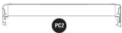
PC2 p Fence
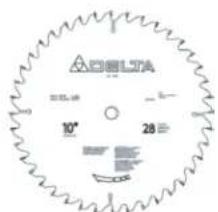
PC3D inch Carbide Tipped Blade
PC4iter Gauge
PC5ade Guard Assembly
PC6 nti-Kickback Pawls
PC7 hroat Plate
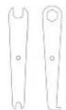
PCB pen End Blade Wrench
PC9 osed End Blade Wrench
PC10ush Stick
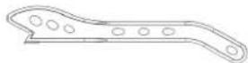
PC11 Stand Part 1
PC12 Stand Part 2
PC13 Stand Legs (4)
UNPACKING
HARDWARE BAG CONTENTS
HP1

HP2

005733

HP3
007085
HP4
006510
HP5
O
O
O
O
005733
HP6
006510
HP7
003640 006459 004306
HP8
HP9
HP1 M8 x 30mm (1 3/16 inch) Carriage Bolt (8)
HP2 Flat Washer 8mm x 14mm x 1.5T (4)
HP3 M8 Plastic Spacer (2)
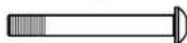
HP4 M8 x 65mm (2 1/2 inch) Hex Socket Head Screw (2)
HP5 M8 Lock Nut (10)
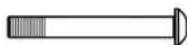
HP8 M8 x 55mm (2 3/16 inch) Pan Head Hex Socket Screw (4)
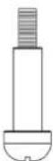
HP7 Handwheel Knob Shoulder Screw
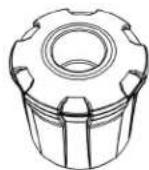
HP8 Height Adjustment Knob
HP9 Combination 4mm Allen Wrench /Phillips Screwdriver
ASSEMBLY
TOOLS NEEDED FOR ASSEMBLY OR ADJUSTMENTS
NOTE: The following tools are not provided with the machine and will be needed for various Assembly steps and Adjustment Procedures throughout the user manual.
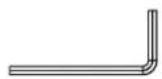
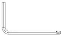
3mm Hex Wrench
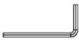
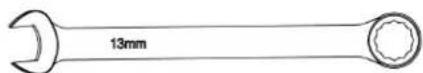
13mm Combination Wrench5mm Hex Wrench
Combination Square
ASSEMBLY
WARNING: When lifting saw, hold it close to your body. KEEP knees bent and lift with your legs, not your back. Fully assemble Saw with Stand Assembly prior to use. Stand Assembly is an integral and necessary part of the support structure for this Saw. DO NOT attempt to substitute a table or other surface for the Stand Assembly. DO NOT modify saw, or create accessories not recommended for use with this Saw. DO NOT connect to power supply until assembly is complete. Make sure power switch is in "OFF" position before connecting to power supply. Avoid contact with Blade Teeth. KEEP Blade stored or lowered when possible.
ASSEMBLING THE STAND
Note: Stand only applicable for 36-6013 X models. 36-6013 models see page 15.
-
Assemble Stand Part 2 PC12 through Stand Part 1 PC11 that has the cross support as shown in Figure 1.
-
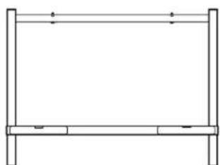
Using the supplied 4mm Combination Allen Wrench HP9 and 13mm Combination Wrench (Not Supplied), secure Stand Assembly with M8 x 65mm Hex Socket Head Screw HP4, M8 Plastic Spacer HP3, 2 Flat Washer 8mm x 14mm x 1.5T HP2, and M8 Lock Nut HP5. See Figure 2. Repeat this for other side.
-
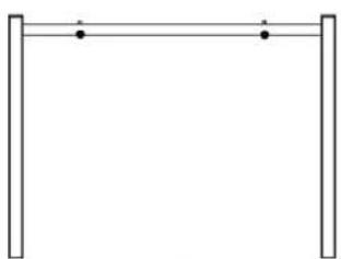
All four holes should face up to mount saw body. See Figure 3 for correct stand parts setup.
NOTE: M8 Plastic Spacer HP3 is between Stand Part 1 PC11 and Stand Part 2 PC12.
- Turn stand upside down to attach legs. With assembled stand open, with the 13mm Combination Wrench (Not Supplied), attach (4) Stand Legs PC13 to the stand using (8) M8 x 30mm (1 3/16 inch) Carriage Bolts HP1 and (8) M8 lock nuts HP5. Tighten lock nuts to secure legs to stand, as seen in Figure 4.
NOTE: DO NOT over tighten lock nuts.
See finished assembly of stand in Figure 4.
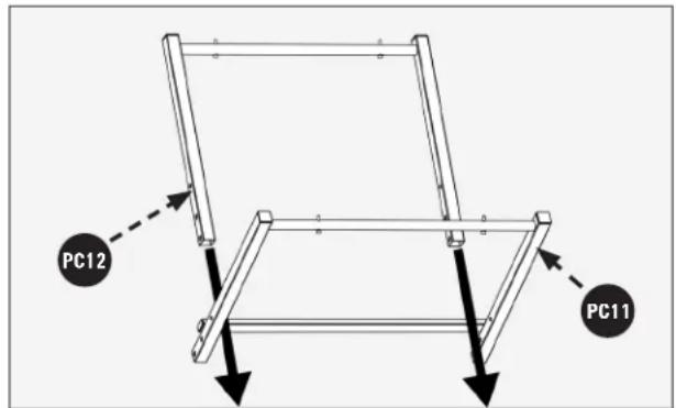
FIGURE 1
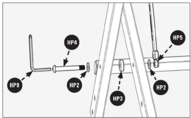
FIGURE 2
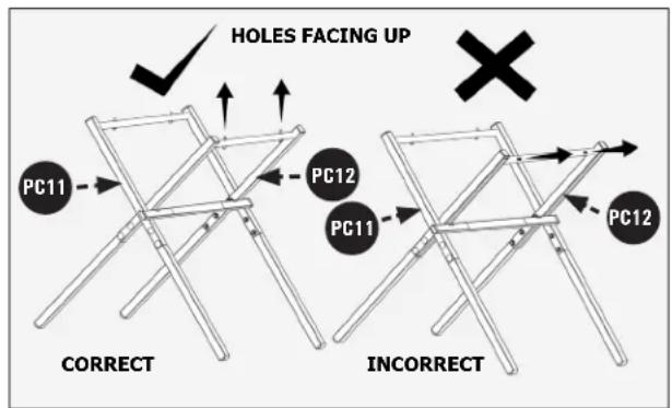
FIGURE 3
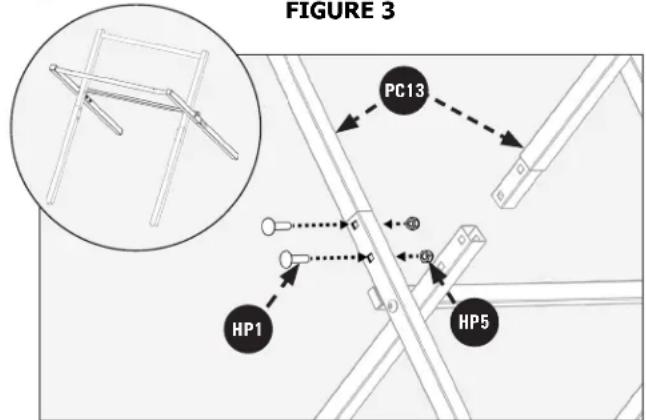
FIGURE 4
ASSEMBLY
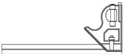
ATTACHING STAND TO SAW
- Place Saw Body on Stand Assembly, while aligning the screw holes in the Saw Stand with the threaded holes in the Saw Base. See Figure 5.
- Tighten (4) M8 x 55mm Pan Head Hex Socket Screws with supplied Combination 4mm Allen Wrench to secure Stand Assembly to Saw.
NOTE: DO NOT over tighten. Hex wrench storage provided on saw near fence storage bracket.
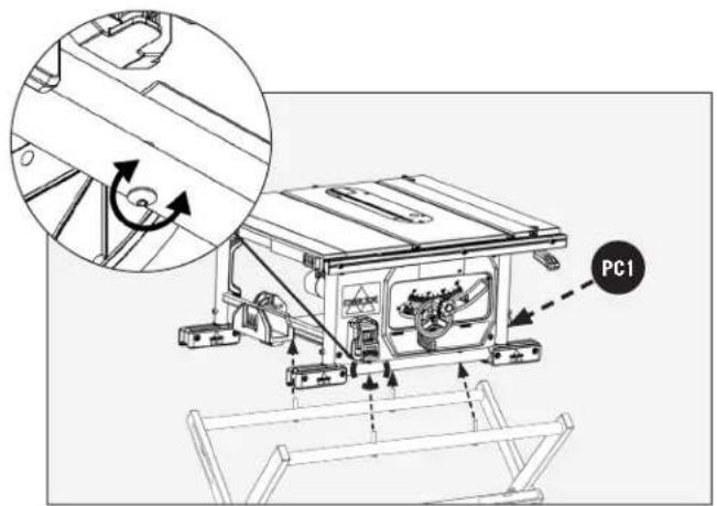
FIGURE 5
ASSEMBLY
HEIGHT ADJUSTMENT KNOB INSTALLATION
- Insert Handwheel Knob Shoulder Screw into Height Adjustment Knob as shown in Figure 6.
- Tighten Shoulder Screw with Combination 4mm Allen Wrench/Phillips Screwdriver or Phillips Screw Driver into the Hand Wheel. Height adjustment Wheel Knob should rotate freely around Shoulder Screw when raising or lowering the Blade with the Height Adjustment Handwheel.
INSTALLING THE BLADE
- Raise Motor/Arbor Assembly to the upper most position to provide easy access to Riving Knife Lock Lever and Arbor Assembly.
- Ensure Riving Knife Lock Lever is in unlock position. See Figure 7.
- Detach the On-Board Wrenches located on the Right Side of the Saw behind blade guard storage in Figure 20 by loosening and removing M8 Wing Nut.
- Place the Open-Ended Wrench on the Spindle Shaft between the Arbor Flange and the Inner Blade Washer. Place the Closed End Wrench over the Arbor Nut.
- Holding the Spindle Shaft in place, loosen and remove the Arbor Nut and Outer Blade Washer. See Figure 7.
NOTE: Use ONLY 10 inch (254mm) diameter Blades with 5/8 inch (16mm) arbor holes, rated at 5,000 rpm or higher, 0.10 inch (2.6mm) min. kerf width and 0.073 inches (1.85mm) max body thickness. ONLY use 10 inch blades designed for woodcutting.
- Place Blade on the Arbor Shaft with the teeth on the Blade pointing toward the front of the saw. Place Outer-Blade Washer on the Arbor Shaft with the large side of the Washer against the Blade, then secure Blade Assembly with Nut. See Figure 8.
- Tighten Nut with Blade Wrenches PC8 and PC9. Open End Wrench will fit on the Arbor Shaft between the Inner Flange Washer and the Motor Assembly (if necessary, turn Arbor Shaft to align Flats on the Arbor Shaft to the Wrench). Closed End Wrench will fit on the Nut. See Figure 9.
- Return Wrenches FCB and FCS to On-Board Storage location and secure the M8 Wing Nut. Position the Riving Knife in the through cut position prior to installation of Throat Plate. See Figure 10.
Details for positioning the Riving Knife are on page 27 "RIVING KNIFE POSITION AND ALIGNMENT".
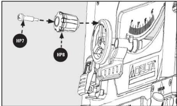
FIGURE 6
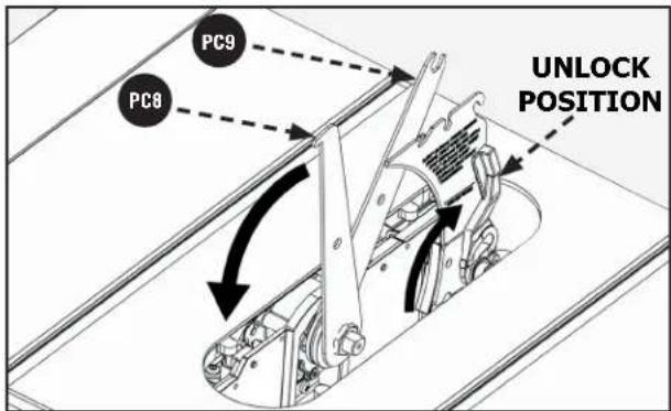
FIGURE 7
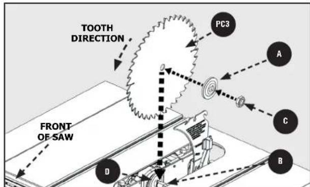
FIGURE 8
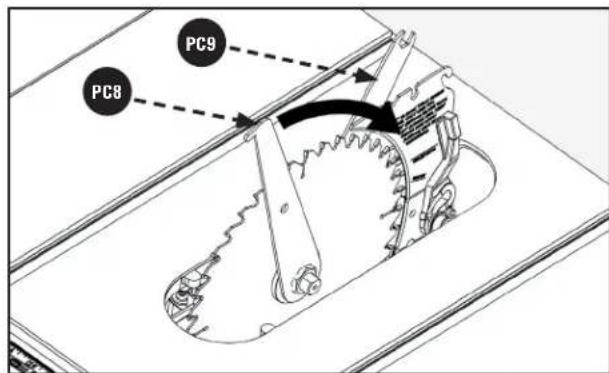
FIGURE 9
ASSEMBLY
WARNING: To reduce the risk of serious injury:
- The Riving Knife MUST be installed for every through cut and for every non-through cut unless the Riving Knife A would interfere with the cut.
- The Riving Knife provided with the Table Saw shall be thicker than the body of the matching Saw Blade provided with the Table Saw but thinner than the kerf width of that Saw Blade.
- ALWAYS use a Blade with the correct thickness to match the Riving Knife. (0.10 inch (2.6mm) min. kerf width and 0.073 inch (1.85mm) max body thickness).
- The Riving Knife MUST be securely positioned in the "up" or "through cut" position when using the Anti-Kickback Pawls and Blade Guard Assembly.
- Make sure the Riving Knife is properly aligned to the Blade. See "RIVING KNIFE POSITION AND ALIGNMENT", page 27.
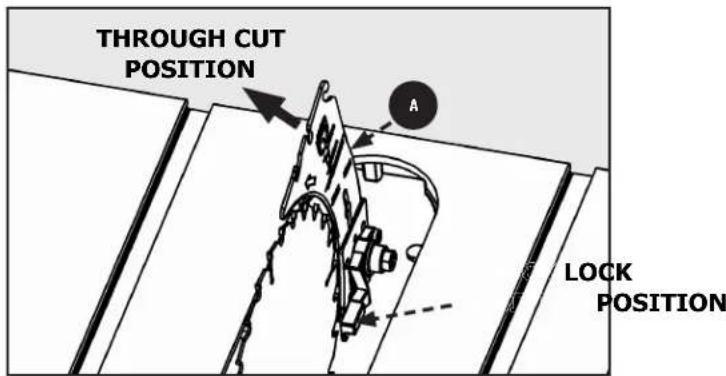
FIGURE 10
THROAT PLATE
NOTE: When installing Riving Knife, Blade MUST be set at 90^ and raised to the maximum height. See "Adjusting the Blade Height" page 23.
To install Throat Plate, lower Blade below Tabletop, then carefully feed the Throat Plate, slotted end first, starting at the rear and moving to the front, keeping the Blade centered within the slot on the Throat Plate.
WARNING: To avoid serious injury the height of the Throat Plate MUST be properly adjusted. Use set screw openings in Throat Plate to make adjustments. To prevent your workpiece from catching on the Tabletop, and to prevent Anti-Kickback Pawls from catching on the Throat Plate, make sure that:
a. The front end of the Throat Plate is flush with the
Tabletop or up to 0.7 mm( 1/36inch) below it,and
b. The back end of the Throat Plate is flush with the tabletop, or up to 0.7mm (1/36 inch) above it.
WARNING: Set screws are provided to accurately adjust throat plate height. DO NOT ATTEMPT TO SCREW THROAT PLATE TO TABLE TOP.
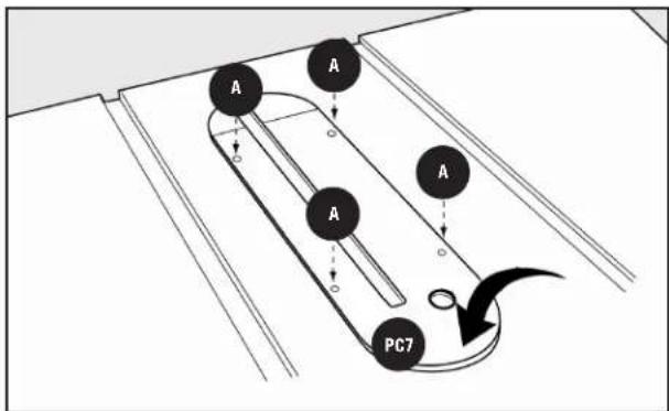
FIGURE 11
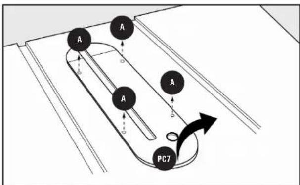
FIGURE 12
ASSEMBLY
ANTI-KICKBACK PAWLS AND BLADE GUARD
ANTI-KICKBACK PAWLS
WARNING: To reduce the risk of serious personal injury, Anti-Kickback Pawls must be in place when making a through cut.
- Refer to Figure 13 and locate the Anti-Kickback Pawls PCB Mounting Slot in the middle of the top edge of the Riving Knife A.
- Slide slot in the middle of the Anti-Kickback Pawls Assembly PCG along the top of the Riving Knife A until the Press Pin B locates the center slot on the Riving Knife A.
- Depress the Press Pin on the Anti-Kickback Pawls Assembly to allow the Assembly to drop into the slot. Push down on the Anti-Kickback Pawls Assembly until it snaps into place and locks. Release Push Pin
NOTE: Pull up on the Anti-Kickback Pawls to make sure it is locked in place.
- To remove the Anti-Kickback Pawls P66, depress the Press Pin and pull the Anti-Kickback Pawls Assembly off the Riving Knife A.
BLADE GUARD
WARNING: To reduce the risk of serious personal injury, the Blade Guard MUST be in place when making a through cut.
- Before installing the Blade Guard Assembly, make sure the riving knife is raised to the thru-cut position. While holding the Blade Guard Assembly in a vertical position, hook the Locating Pin at the back end of the Blade Guard Assembly into the slot at the back edge of the Riving Knife. See Figure 14.
- Rotate the Blade Guard Assembly toward the front of the Saw until the Support Arms of the Blade Guard Assembly are parallel to the Table see Figure 15.
- See Figure 16 (next page). While holding down on the front of the support arms of the Guard press the Blade Guard Lock Tab A down until it snaps into the locked position. Check to make sure the Guard is locked onto the Riving Knife by pulling on the Guard. If the Guard is not locked, the Blade Guard Lock Tab A will flip up to the unlocked position.
WARNING:ort Arm
of the Blade Guard
Assembly is not parallel to the Table, the Riving Knife is not in the raised (through cut) position. Remove Blade Guard Assembly and Anti-Kickback pawls and raise Riving Knife, then reinstall the Anti-Kickback pawls and the Blade Guard Assembly.
- Raise and lower each side of the Blade Guard to verify free movement of the Guard System. Be sure the Guard System can be raised enough to clear your workpiece.
NOTE: Blade alignment with Riving Knife can be adjusted. See: "RIVING KNIFE POSITION AND ALIGNMENT", page 27. Check the Blade Guard for clearances and free movement.
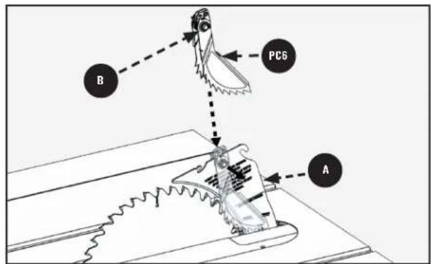
FIGURE 13
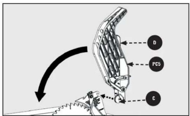
FIGURE 14
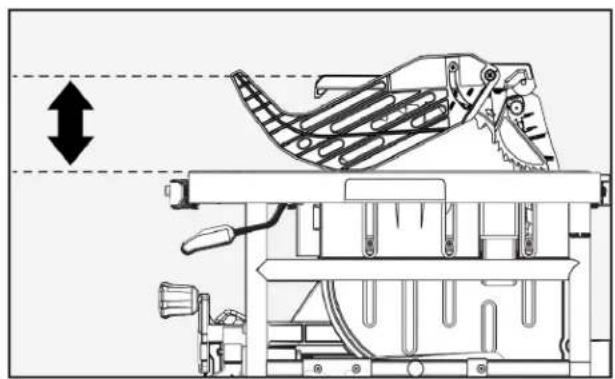
FIGURE 15
ASSEMBLY
To remove the Blade Guard Assembly:
See Figure 16.
- Lift the Blade Guard Assembly Lock Tab to the unlocked position.
- Rotate the Guard Support back and slide the Locating Pin from the Riving Knife slot.
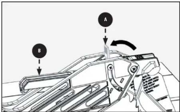
FIGURE 16
INSTALLING THE FENCE
The fence can be positioned on one of the three pairs of tabs. Two on the right side of the blade and one on the left side.
- Hold fence perpendicular to the table.
- Starting with the rear of the fence, engage the rear notch on the rear tab.
- Lower the front notch onto the corresponding front tab
- Press in on the lock lever to lock fence in place. See Figure 17.
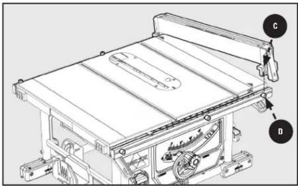
FIGURE 17
REMOVING THE FENCE
- Release the lock lever to unlock the fence.
- Disengage the front tab and remove the fence from the front to the rear.
See Figure 18.
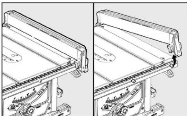
FIGURE 18
ASSEMBLY
ON-BOARD STORAGE
Storage is located on the left side and right side of the machine as seen in Figures 19 & 20.
Left Side Storage Figure 19:

Rip Fence

Push stick

Miter Gauge
Right Side Storage Figure 20:

Blade Wrenches

Riving Knife (with Blade Wrenches)

Blade Guard Assembly

Anti-Kickback Pawls (Behind Blade Guard Assembly)
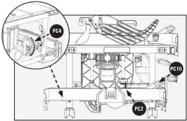
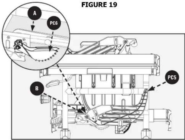
FIGURE 20
MAKING ADJUSTMENTS
LEVELING THE THROAT PLATE
To install throat plate PC7, slip tab into slot at back of saw and push down the front of the throat plate to secure in place. See Figure 21.
NOTE: There are four screws pre-assembled to the throat plate that are used for leveling the throat plate if necessary.
- Turn screws clockwise to raise the throat plate, counter clockwise to lower.
- Throat Plate should not be above the table or more than 1/36 inch (0.7mm) below the table on infeed side. On outfeed side plate should be below the table or no more than 1/36 inch (0.7mm) above the table.
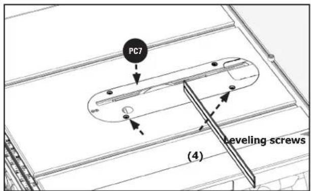
FIGURE 21
MAKING ADJUSTMENTS
ADJUSTING BLADE PARALLEL TOMITER GAUGE GROOVE (HEEL)
- Blade A MUST be parallel to miter gauge groove so that wood does not bind, resulting in kickback. Failure to do so could result in serious personal injury.
To reduce risk of injury from kickback, align miter gauge groove to blade A following any blade adjustments.
DO NOT loosen any screws for this adjustment until alignment has been checked with a square to be sure adjustments are necessary. Once screws are loosened, items MUST be reset.
NOTE: Unplug saw. Remove blade guard and anti-kickback pawls. Raise the blade to maximum height by turning height adjusting wheel.
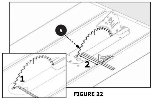
- Mark beside one of blade teeth at front of blade Figure 22. Place the combination square against the marked tooth at the front of the blade with the head of the square against the miter gauge groove as shown.
- Turnblade so that marked tooth (1) is at back. Move combination square to the rear and again measure the distance (2). If the distances are the same, blade is parallel. See Figure 23.
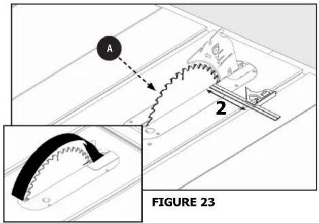
If the distances are different:
- Using a 5mm Hex Wrench loosen the front trunnion bolts 1/2 turn, found below the table top. See Figure 24.

FIGURE 24
MAKING ADJUSTMENTS
- Using a 5mm Hex Wrench loosen the rear trunnion bolts 1/2 turn, found below the table top. See Figure 25.
- If the rear of the blade was too close to combination square, place a block of wood on the right side of the blade. Lightly tap with a small hammer or rubber mallet to achieve the correct parallelism adjustment. See Figure 26.
- Re-tighten the trunnion bolts with 5mm Hex Wrench. Re-check alignment after bolts are re-tightened.
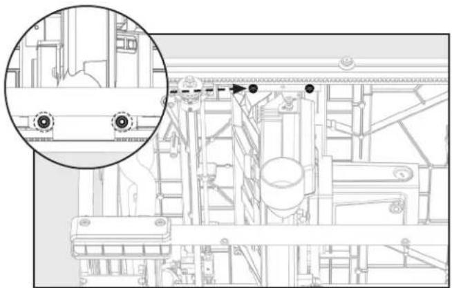
FIGURE 25
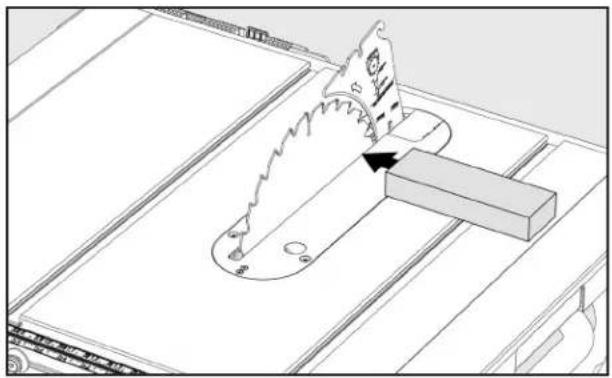
FIGURE 26
SQUARING THE BLADE VERTICALLY TO THE TABLE
- Place a combination square against the table and the side of the blade, avoiding contact with the teeth. See Figure 27.
- If it is not square, adjust the 0^ stop as shown in "Adjusting The Bevel Stops".
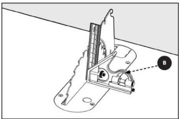
FIGURE 27
MAKING ADJUSTMENTS
ADJUSTING THE BEVEL STOPS
Adjusting 0 Degree Positive Stop
If the blade is not vertically square to the table, you MUST adjust the 0^ positive stop, located on the far left end of the bevel track as shown in Figures 28 and 28a.
- Make sure your saw is "OFF" and unplugged.
- Secure the bevel lock and raise the blade to its uppermost position.
- Unlock the bevel locking lever and slide the elevation handwheel to the 0^ positive stop position. Lock bevel lock lever.
- Place a combination square next to the blade and check for 90^ alignment.
- If the blade is not squared 90^ to the table, loosen the hex head screw using the supplied Combination 4mm Allen Wrench/Phillips Screwdriver and adjust the cam until the blade is square to the table.
- Retighten the screw, and check for 90^ alignment.
Adjusting 45 Degree Positive Stop
If the blade is not showing an accurate 45^ to the table, you MUST adjust the 45^ positive stop, located on the far right end of the bevel track (maximum 45^ ) as shown in Figures 29 and 29a.
- Make sure your saw is "OFF" and unplugged.
- Secure the bevel lock and raise the blade to its uppermost position.
- Unlock the bevel locking lever and slide the elevation handwheel to the 45^ positive stop position.
- Place the 45^ face of a combination square next to the blade and check for 45^ alignment.
- If the blade is not 45^ to the table, loosen the hex head screw using the supplied 4mm Allen Wrench/Phillips Screwdriver and adjust the cam until the blade is at 45 degrees to the table.
- Retighten the screw, and check for 45^ alignment.
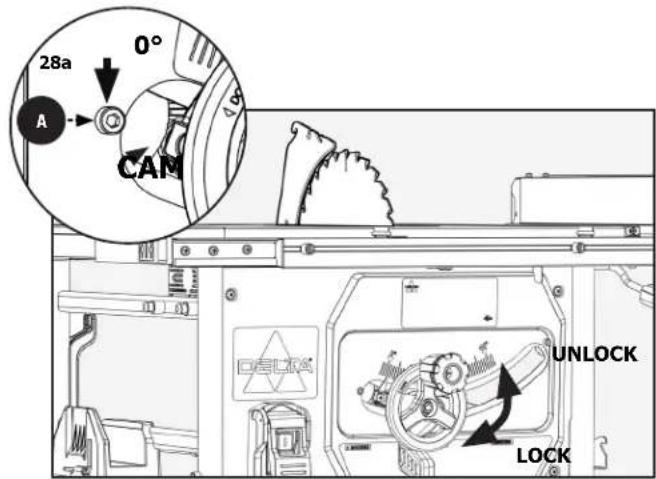
FIGURE 28
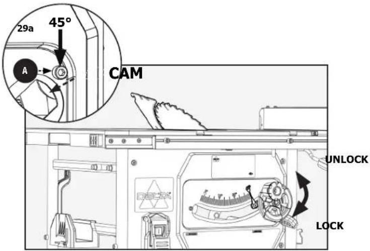
FIGURE 29
MAKING ADJUSTMENTS
- For all through cuts, the top of the blade points should be above the workpiece and the bottom of the blade gullets are below the top surface of workpiece.
- For non-through cuts, the top of the blade points should be set to the depth of the cut.
To adjust the height of the blade, see Figure 30 and do the following:
- Make sure the bevel locking lever position.

- Adjust the blade height by turning the Height Adjustment Handwheel. Clockwise will raise the blade and counterclockwise lowers it.
CHANGING THE BEVEL
See Figure 30.
- Unlock the bevel locking lever by pulling it into the unlock position.
- Holding knob/wheel A, slide the handwheel to the desired angle.
- When the blade is at desired angle, lock the bevel locking lever by pushing it down to the lock position.
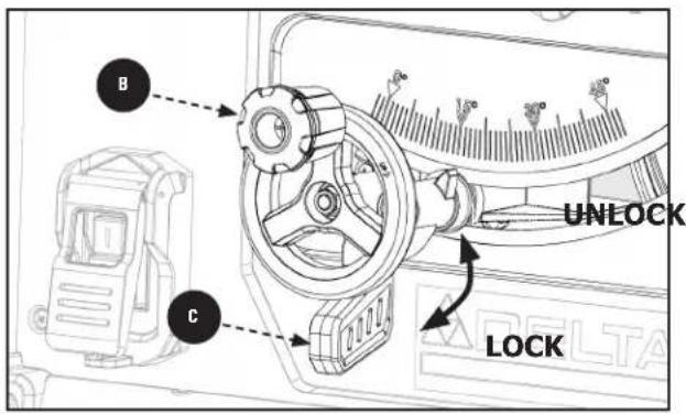
FIGURE 30
To reduce the risk of injury, ALWAYS make sure the rip fence is parallel to the blade before beginning any operation.
- Lift extension lock lever to unlock position.
- Slide fence in or out until the desired cutting dimension is achieved.
- Push extension lock lever lock down to engage the lock.
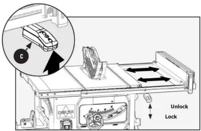
FIGURE 31
MAKING ADJUSTMENTS
USING COLOR-CODED SCALES
Each corresponding scale should be used to measure the distance between the inside face of the blade to the inside face of the fence. Adjust the width of the table saw by using the table extension. Release the table "lock" by lifting the extension lock handle upwards.
BLACK TAB
The black tab correspond to the black scale with white numbers.
- The black tabs in the middle of the rail can be used for right rip cut 0 inches to 15 inches.
- To use the black scale with white numbers, insert the fence notches into the black tab on the rail and use clear indicator. See Figure 32.
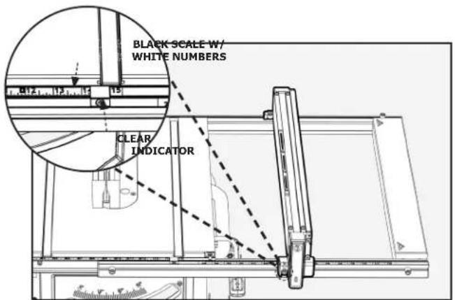
FIGURE 32
WHITE TAB
The white extension tabs correspond to the white scale with black numbers.
- The white tabs on the right of the rail can be used for right rip cut 10 inches to 25 inches.
- To use the white scale with black numbers, insert the fence notches into the white extension tabs on the rail and use red indicator.
See Figure 33.
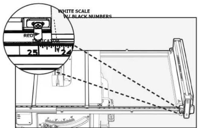
FIGURE 33
BLUE TAB
The blue tabs correspond to the black scale with blue numbers.
- The blue tabs on the left of the rail can be used for left rip cut 0 inches to 12 inches.
- To use the black scale with blue numbers, insert the fence notches into the blue tabs on the rail and use clear indicator. See Figure 34.
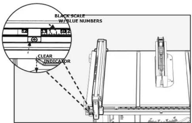
FIGURE 34
MAKING ADJUSTMENTS
ADJUSTING EXTENSION TAB PARALLELISM
- Using a precision measuring tool, measure the distance from the inside face of the Blade to the edge of the Miter Slot. See Figure 35.
- Using the correct scale, slide the fence so that the indicator reads the value that was recorded in Step 1 and lock the Rails in place.
- If the two values agree, there is no need for adjustment. If the values are not the same, you will need to re-adjust your front and rear extension tabs.
- Using supplied 4mm Allen wrench in a counter-clockwise motion, loosen both front and rear extension tabs. See Figure 36.
- Move the extension tabs (with the fence attached) so that the inside face of the fence is flush with the edge of the miter slot (that was measured in Step 1). See Figure 37.
- Once the Fence is the correct distance from the blade and flush with the miter slot edge from front to back, you may use the 5/32 inch Allen Key to re-tighten the extension tabs.
- To check this procedure, with the fence on the extension tabs, slide the fence to a couple of different distances from the blade and check to ensure that the scale readings are accurate.
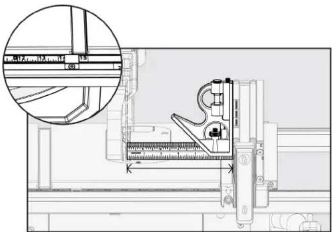
Figure 35
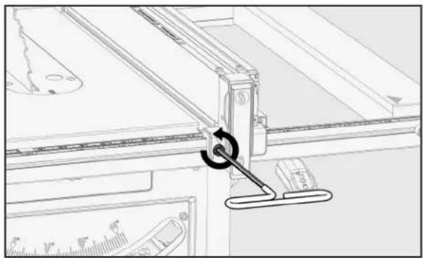
Figure 36
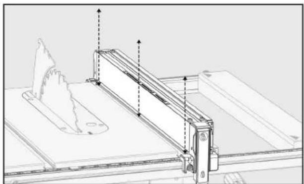
Figure 37
RIVING KNIFE POSITION AND ALIGNMENT
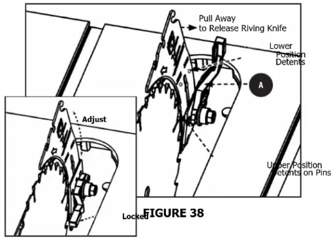
RIVING KNIFE HEIGHT SETTINGS
See Figure 38.
The height of the riving knife should be adjusted based on the type of cut being made. For all through cuts (when the wood is completely severed), it should be in the raised position, with anticlick pawls and guard installed. For non-through cuts (when the blade does not penetrate the top of the workpiece), the riving knife should be in the lowered position and anti-kick pawls and guard removed.
TO RAISE OR LOWER THE RIVING KNIFE:
- Remove the blade guard, anti-kickback pawls, and throat plate and raise blade to the full height above the table.
- Locate the locking lever near the base of the riving knife.
- Rotate the lever by turning clockwise to unlock and release the riving knife from its locked position.
- Using your hand positioned near the top of the knife, lean the knife outward away from the two locking pins beside its middle slot. This now frees the knife to slide into the upward/cut through position.
- Lift the knife upward along the slot until you feel the new locking pins position.
- Release the knife and it should snap into its new position; wiggle if necessary.
- Return the locking lever to the locked position. If you have done this properly the riving knife will be aligned with the blade. If it is not retrace your steps until it does. The appropriate marking will be seen at the table top level.
NOTE: When adjusting the riving knife up or down, be sure to pull in a radial motion, as shown.
WARNING:
DO NOT operate saw unless riving knife is
securely clamped in the raised position for through cutting or the lowered position for non-through cutting, unless Riving Knife would interfere with the cut.
WARNING:
NEVER use a blade that does not match the
dimensions indicated for use with your riving knife.
RIVING KNIFE POSITION AND ALIGNMENT
Location point for NON-THROUGH CUT POSITION.
NOTE: Riving knife is located in this position for NON-THROUGH cuts and is also in this position when packaged for shipment.
Location point for THROUGH CUT POSITION see Figure 39. (Operator should adjust the riving knife to this position when making THROUGH CUTS.)
(NOTE: You MUST locate the riving knife in THROUGH CUT POSITION prior to making any alignment adjustments to the riving knife.)
NOTE: You will need a long handled 3mm hex wrench for BB2 and BB3 and 4mm for AA.
PARALLEL ALIGNMENT
The plane of the riving knife is parallel to the plane of the blade but the riving knife and the blade are not in line with each other.
If a parallel adjustment is required use Figure 39 and Figure 40 to make the following adjustments:
- Loosen the two hex socket head set screws using a 4mm hex wrench.
- Tighten or loosen the adjustment screw using a 3mm hex wrench to adjust the datum line of the riving knife to be aligned with the blade.
- Adjust set screw and using a 3mm hex wrench, to assist with the alignment of the riving knife to be parallel to the blade.
- Tighten hex socket head screws
HORIZONTAL ALIGNMENT
The plane of the riving knife appears to be twisted in comparison to the plane of the blade. (Can be seen looking straight down on the blade and riving knife.)
If the riving knife has horizontal misalignment, adjust as follows using Figure 39 and Figure 41.
- Loosen the two hex socket head screws
- Adjust screw to align the riving knife to the blade, if still out of alignment then adjust until proper alignment is achieved. DO NOT adjust
- Tighten screws
VERTICAL ALIGNMENT
The plane of the riving knife appears to be twisted in comparison to the plane of the blade from the bottom of the riving knife to top of the riving knife. (Can be seen looking from the front of the saw.)
If the riving knife has vertical misalignment, adjust as follows using Figure 39 and Figure 42.
- Loosen the two hex socket head screws
- Make adjustments to BB2 and BB3, to align riving knife to the blade. No adjustment is needed for BB1.
- Tighten screws AA
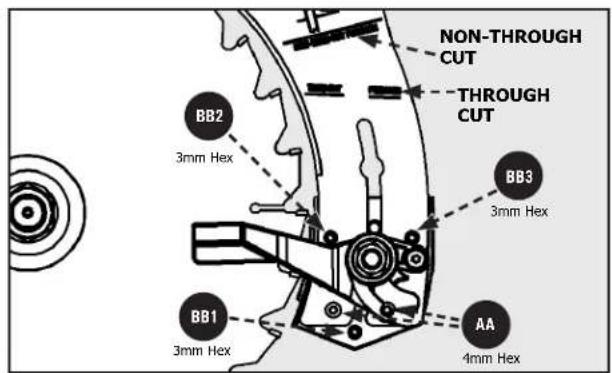
FIGURE 39
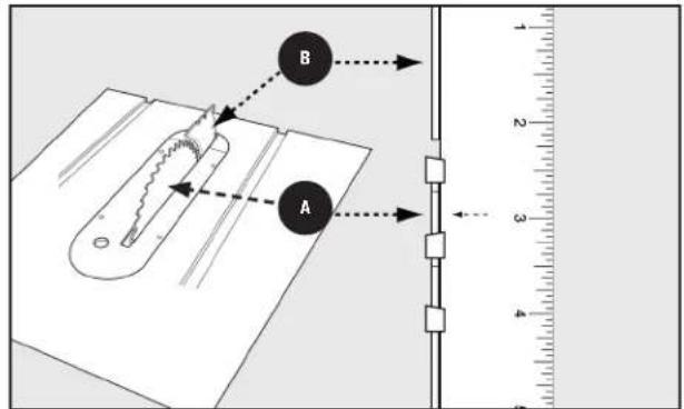
FIGURE 40
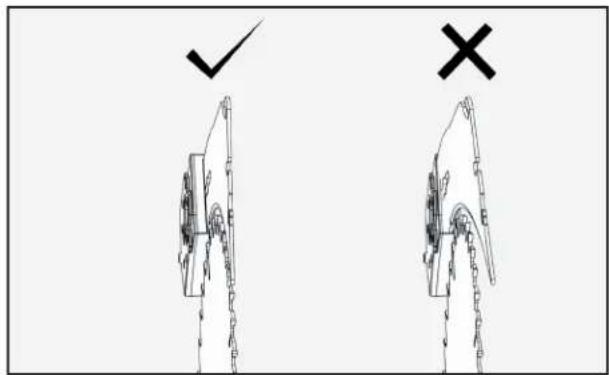
FIGURE 41
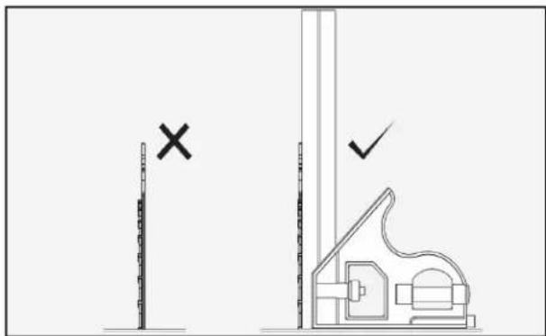
FIGURE 42
OPERATION
WARNING:
Failure to comply with the following warnings may result in serious personal injury.
READ ENTIRE MANUAL. In addition to reading these operating instructions, it is important to read and understand the entire manual before operating this saw. Follow all applicable instructions regarding assembly, preparation, and adjustment prior to making any cuts and comply with all safety rules and warnings in this section and elsewhere throughout this manual.
- Each time you use the saw, run through the following checklist:
- Are the power source and power connections adequate for the saw?
- Are the saw and work area free of clutter and by-standers?
- Is the blade tight and properly aligned?
- Does the riving knife thickness match the blade?
- Are the blade and riving knife properly aligned?
- Is the operator qualified to make the cut and familiar with all of the relevant safety rules, warnings and instructions included in this manual?
- Is the operator and everyone in proximity to the saw wearing appropriate eye, hearing and respiratory equipment?
- Are the bevel angle and height adjustment knobs locked in the proper position?
- Make sure the blade is the proper height for your cutting operation.
- If ripping, is the rip fence parallel to the blade and securely locked in position?
- If crosscutting, is the miter gauge knob tight?
- If making through cuts with a standard blade, are the blade guard, riving knife and anti-kickback pawls properly attached and properly functioning with both guards contacting the table surface?
- Is there proper clearance and support for the workpiece as it leaves the blade?
- Are any cutting aids needed? If so, are they in place, or within reach for proper use?
-
The use of attachments and accessories not recommended by DELTA may result in injury.
-
Replace or sharpen the anti-kick pawls when the points become dull.
- Make sure saw is stable and cutting can be accomplished without tipping the saw. DO NOT attempt to cut large workpieces without securing saw to a stable surface.
- NEVER use the fence and miter gauge together without using a cutoff block as as described in the manual.
- The proper throat plate MUST be in place at all times.
- If your saw makes an unfamiliar noise or if it vibrates excessively, cease operating immediately until the source has been located and the problem corrected.
Use saw blade guard, anti-kickback pawls, and riving knife assembly for every possible operation, including all through-cut sawing.
Push the workpiece past the saw blade prior to releasing control.
NEVER rip a workpiece that is twisted or warped, or does not have a straight edge to guide along the fence.
NEVER saw a large workpiece that cannot be controlled.
NEVER use the fence as a guide or length stop when crosscutting.
NEVER saw a workpiece with loose knots, flaws, nails or other foreign objects.
NEVER rip a workpiece shorter than 10 inches (254mm).
NEVER use a dull blade. A dull blade should be replaced or re-sharpened.
NEVER perform freehand cutting, plunge cutting, re-sawing or cove cutting.
OPERATION
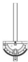
DUST COLLECTION
Connect a shop vacuum or dust collection hose to dust port on back of saw for best dust collection. Dust port is designed for a 2 1/2 inch vac hose. See Figure 43.
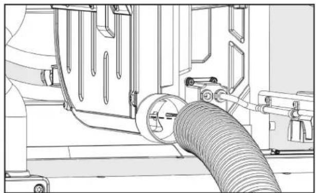
FIGURE 43
TURNING THE SAW ON AND OFF
The ON/OFF paddle switch is located on the left side of the front panel of the saw.
- Press the green button A to turn the saw ON.
- Press the switch down to turn the saw OFF.
- When not in use, the saw should be turned off and the power switch locked out to prevent unauthorized use. To lock out power switch, use a standard long shackle lock, with a shackle post no larger than 9/32 inch (7mm) diameter.
See Figure 44.
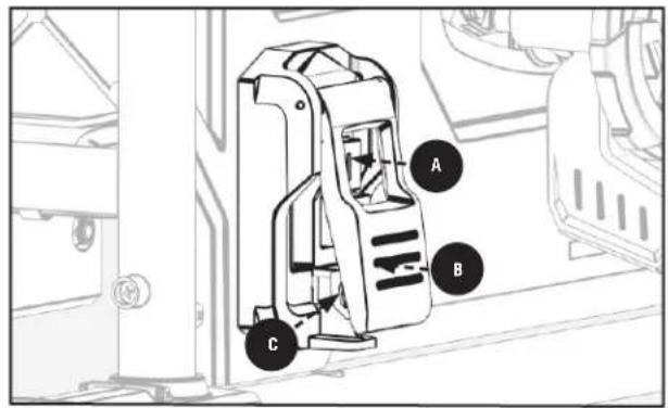
FIGURE 44
TRANSPORTING THE SAW
- Return side extension table to inner position lock side extension into place.
- Stow away the Fence, Miter Gauge, Blade Guard, and Kickback Pawls.
- Lower riving knife to the non-through.
- Remove the (4) M8 x 55mm Pan Head Hex Socket Screws that secure the Saw to the Stand. See "ATTACHING STAND TO SAW" for further detail.
Once the saw is removed from the stand, it is recommended that the saw be moved using two people. A possible carry point is the handle located on the right side of the saw. As seen in Figure 45.
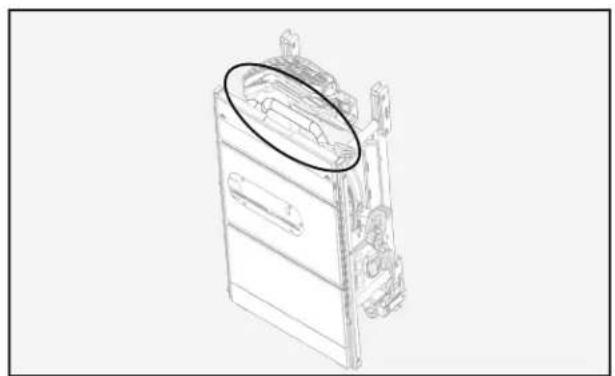
FIGURE 45
MAKING CUTS
WARNING:
Failure to comply with the following warnings may result in serious personal injury.
- NEVER touch the free end of the workpiece (the cut-off side beyond the front edge of the blade), while the power is on and/or the saw blade is rotating. Blade contact or binding may occur, resulting in a thrown workpiece.
- When sawing a long workpiece or a panel, use a work support, such as a sawhorse, rollers or out-feed table at the same height as the table surface of the saw.
- NEVER try to pull the workpiece back or lift it off the table, turn the switch off, allow the blade to stop, raise the anti-kickback teeth on each side of the riving knife if necessary, and slide the workpiece out.
-
Before connecting the table saw to the power source or operating the saw, ALWAYS inspect the blade guard assembly and riving knife for proper alignment and clearance with the saw blade. Check alignment after each change of beveling angle.
-
A rip fence should ALWAYS be used for ripping operations to prevent loss of control and personal injury. ALWAYS lock the fence to the rail. NEVER perform a ripping operation freehand.
- When making bevel cuts, place the fence on the right side of the blade so that the blade is tilted away from the fence and hands. KEEP hands clear of the blade and use a push stick to feed the workpiece unless the workpiece is large enough to allow you to hold it more than 6 inches (152mm) from the blade.
- Before leaving the saw unattended, lock out power switch, or take other appropriate measures to prevent unauthorized use of the saw.
- NEVER stand in front of the workpiece.
- ALWAYS stand on the same side of the blade as the fence during a rip cut and the miter gauge during a cross cut.
Beveled Cross Cut Beveled Rip Cut Compound Miter Cut
MAKING CUTS
RIP CUTS
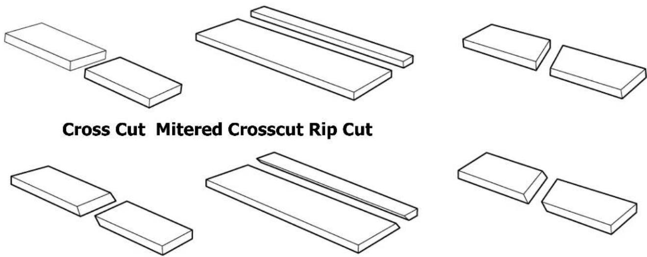
- Rip cutting is performed predominantly in a parallel direction with the grain of the wood.
-
Make sure blade is parallel to miter gauge slot prior to cutting. Instructions for adjustment on page 27.
-
Remove miter gauge.
- Make sure bevel angle is set to 0^ .
- Set blade to correct height for workpiece.
- Install rip fence and lock it down parallel with and at desired distance from blade. See page 18.
- KEEP fingers at least 6 inches from the blade at all times. When hands and fingers cannot be a safe distance from the blade, select a larger workpiece, or use a push stick and other cutting aids, as needed, to control the workpiece.
- Make sure the workpiece is clear of the blade (at least 1 inch or 25mm away) before starting the saw.
- Turn saw on.
- Stand alongside the workpiece on the same side of the blade as the fence.
- Hold the workpiece flat on the table and against the fence. The workpiece MUST have a straight edge against the fence and MUST NOT be warped, twisted or bowed. See proper hand position in Figure 46.
- Let blade build up to full speed before moving workpiece into the blade.
- Both hands can be used while starting the cut as long as hands remain 6 inches from the blade.
- KEEP the workpiece against the table and fence and slowly feed the workpiece rearward all the way through the saw blade. DO NOT overload the motor by forcing the workpiece into the blade.
BEVEL RIPPING
Bevel ripping is the same as ripping except the bevel angle A is set to an angle other than 0^ . When making a bevel rip cut, place the fence on the right side of the blade so that the blade is tilted away from the fence and hands. See Figure 47.
-
Avoid bevel rip cuts with majority of material on left side of blade.
-
Use the push stick and any other cutting aids, as needed, to hold the workpiece against the table and fence, and push the workpiece past the blade. A push stick is included with this saw, and instructions are included to make additional push sticks and other cutting aids.
- DO NOT push or hold onto the free or cut-off side of the workpiece.
- Continue pushing the workpiece until it is clear of the blade. DO NOT overload the motor by forcing the workpiece into the blade.
- When cut is complete, turn saw OFF. Wait for blade to come to a complete stop before removing workpiece from table.
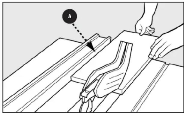
FIGURE 46
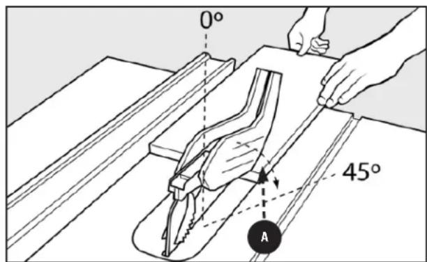
FIGURE 47
MAKING CUTS
CROSScutting
- Cross cutting is performed predominantly in a perpendicular direction with the grain of the wood. The fence can be used to support a block being used as a cut-off gauge, as discussed below.
- Make sure blade is parallel to miter gauge slot prior to cutting. Instructions for adjustment on page 20.
- NEVER use the fence as a guide or length stop when crosscutting, unless you are using the fence as described on page 36, Figure 58 of this manual.
- The cut-off piece MUST NEVER be confined in any through-sawing (cutting completely through the workpiece) operation—to prevent pinching blade which may result in a thrown workpiece and possibly injury.
- When using a block as a cut-off gauge, the block MUST be at least 3/4 inch (19mm) thick. It is very important that the rear end of the block be secured in a position where the workpiece is clear of the block before it enters the blade to prevent binding of the workpiece.
You can use the miter gauge in either table slot on non-bevel cuts. To increase surface area of miter gauge face, add an auxiliary face. See "CUTTING AIDS" section on page 35 of this manual.
To make a crosscut, see Figure 48 and follow this process:
- Remove rip fence.
- Make sure bevel angle is set to 0^ .
- Set blade to correct height for workpiece.
- Place miter gauge in either miter slot.
- Set miter gauge to 90^ and tighten miter gauge lock knob. Stand alongside the workpiece on the same side of the blade as the miter gauge.
BEVEL CROSScutTING
Bevel crosscutting is the same as crosscutting except the bevel angle A is set to an angle other than 0^ . When making a bevel crosscut, place the miter gauge in the right miter slot so that the blade is tilted away from the miter gauge and hands. See Figure 49.
MITER CUTS
Miter cuts are cross cuts with the miter gauge set at an angle other than 90^ . Miter gauge can be adjusted to one of the 8 positive stop angles or as desired to an individual angle increment.
WARNING:
-
Miter angles more than 45^ may force the blade guard assembly into the saw blade causing damage to the blade guard assembly and personal injury. Before starting the motor, test the operation by feeding the workpiece into the blade guard assembly. If the blade guard assembly contacts the blade, place the workpiece under the blade guard assembly but not touching the blade - before starting the motor.
-
Hands MUST remain at least 6 inches from blade throughout entire cut. If workpiece is too small to KEEP hands at least 6 inches away from the blade, select a larger workpiece, or attach an auxiliary face to the miter gauge and attach workpiece to auxiliary face. For instructions about making auxiliary faces, see "CUTTING AIDS" section on page 35 of this manual.
- Make sure the workpiece is clear of the blade - at least 1 inch or 25mm away - before starting the saw.
- Turn saw on.
- Let blade build up to full speed before moving workpiece into the blade.
- Hand closest to blade should be placed on miter gauge lock knob and hand farthest from blade should hold workpiece firmly against the miter gauge face. DO NOT push or hold onto the free or cut-off side of the workpiece.
- Slowly feed the workpiece rearward all the way through the saw blade. DO NOT overload the motor by forcing the workpiece into the blade.
- When cut is complete, turn saw OFF. Wait for blade to come to a complete stop before removing cut off piece from table.
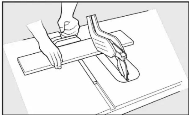
FIGURE 48
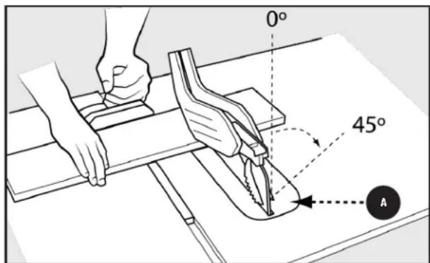
FIGURE 49
- Certain workpiece shapes, such as molding may not lift the blade guard assembly properly. With the power off, feed the workpiece slowly into the blade guard area and until the workpiece touches the blade. If the blade guard assembly contacts the blade, place the workpiece under the blade guard assembly - but not touching the blade - before starting the motor.
MAKING CUTS
COMPOUND MITER CUTS
This is a combination of bevel crosscutting and mitering.
See Figure 50 and follow the instructions for both bevel crosscutting and mitering. Remember to use the right miter slot on the right side of the blade for all bevel cuts.
- DO NOT attempt compound miter cuts, with blade beveled and miter fence angled, until you are thoroughly familiar with the basic cuts and understand how to avoid kickback.
LARGE PANEL CUTS
Place workpiece supports at table height behind and/or to the side of saw to support workpiece as needed. Depending on shape of panel, use rip fence or miter gauge to control workpiece. If a workpiece is too large to use either a rip fence or a miter gauge, it is too large for this saw.
WARNING:
DO NOT allow bystanders to hold or support
any portion of the workpiece.
NON-THROUGH CUTS
The use of a non-through cut is essential to cutting grooves and rabbets. Non-through cuts can be made using a standard blade having a diameter of 10 inches or less. Non-through cuts are the ONLY type of cuts that should be made without the blade guard assembly installed. Make sure the blade guard assembly and anti-kickback pawls are reinstalled upon completion of this type of cut.
WARNING:
- When making non-through cuts, follow all applicable warnings and instructions listed below in addition to those listed above for the relevant through cut.
- When making a non-through cut, blade is covered by workpiece during most of cut. Be alert to exposed blade at start and finish of every cut.
- NEVER feed wood with hands when making any nonthrough cuts such as rabbets or grooves. ALWAYS use miter gauge, push blocks or push sticks, and featherboards where appropriate.
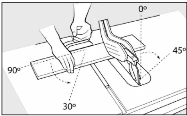
FIGURE 50
- In addition to this section, read the appropriate section which describes the type of through cut. For example, if your nonthrough cut is a straight cross cut, read and understand the section on straight cross cuts before proceeding.
- Once all non-through cuts are completed, unplug saw and return riving knife to through cut position. Install anti-kickback pawls and blade guard.
- Carefully follow the instructions accompanying any specialized blades for proper installation, set up and operation.
MAKING A NON-THROUGH CUT
Once all non-through cuts are completed, unplug saw and reinstall riving knife in raised position. Install anti-kickback pawls and blade guard.
- Unplug saw.
- Unlock bevel lock.
- Adjust bevel angle to 0^ .
- Lock bevel lock.
- Remove blade guard and anti-kickback pawls.
-
Place riving knife in "lowered" position. See "RIVING KNIFE POSITION AND ALIGNMENT" Section on page 26.
-
Set blade to correct depth for workpiece.
- Depending on shape and size of wood, use either rip fence or miter gauge.
-
Plug saw into power source and turn saw on.
-
Let blade build up to full speed before moving workpiece into blade.
- ALWAYS use push blocks, push sticks, and/or featherboards when making non-through cuts to reduce the risk of serious injury.
- When cut is made, turn saw off. Wait for blade to come to a complete stop before removing workpiece.
- Once all non-through cuts are completed, unplug saw and return riving knife to through cut position. Install anti-kickback paws and blade guard.
CUTTING AIDS AND ACCESSORIES
PUSH STICK
In order to operate your table saw safely, you MUST use a push stick whenever the size or shape of the workpiece would otherwise cause your hands to be within 6 inches (152mm) of the saw blade or other cutter. A push stick is included with this saw.
No special wood is needed to make additional push sticks as long as it is sturdy and long enough with no knots, checks or cracks. A length of approximately 15.7 inches (400mm) is recommended with a notch that fits against the edge of the workpiece to prevent slipping. It's a good idea to have several push sticks of the same minimum length, 15.7 inches (400mm), with different size notches for different workpiece thicknesses.
The shape can vary to suit your own needs as long as it performs its intended function of keeping your hands away from the blade. Angling the notch so the push stick can be held at a 20 to 30-degree angle from the saw's table will help you to hold down the workpiece while also moving it through the blade.
To construct a push stick, refer to the layout see Figure 51.
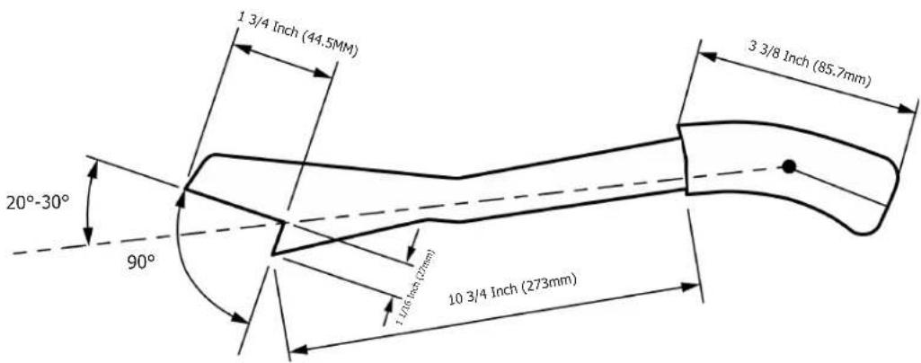
FIGURE 51
There are two miter gauge grooves. One on either side of the blade. When making a 90^ cross cut, use either groove. For beveled cross cuts use the groove on right so that the blade is tilted away from miter gauge and hands.
- Loosen the miter gauge lock knob A. Rotate the gauge until desired angle on scale is reached. Re-tighten lock knob A.
See Figure 52.
NOTE: The miter gauge has index points at 90, 75, 60, 45, & 30 degrees both left and right.
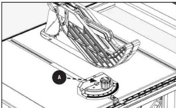
FIGURE 52
CUTTING AIDS AND ACCESSORIES
AUXILIARY MITER GAUGE FACING
An auxiliary miter gauge facing is used to increase the surface area of the miter gauge face.
The use of miter gauge with auxiliary facing is the same as original miter gauge (without auxiliary facing). See Page 34 for the use of miter gauge.
If desired, you can fit the miter gauge with an auxiliary wood facing that should be at least 1 inch (25mm) higher than the maximum depth of cut, and at least as wide as the miter gauge.
This auxiliary wood facing can be fastened to the front of the miter gauge by using (2) M6 or 1/4-20 flat head screws and nuts, placing the nuts into the slots provided in the face of the miter gauge body.
See Figure 53.
Make sure the screws are long enough to secure the facing.
WARNING: Flat head screws MUST be recessed into face of board.
FLIP DOWN FENCE
Use the flip down fence when cutting thin stock in which the blade guard would normally interfere with the fence to make the desired cut.
To utilize this flip down feature for small, narrow cuts, you MUST slide the flip down part of the fence underneath the blade guard, so that the blade is still covered safely by the blade guard. Please see Figure 54.
For thin materials use the fence on the left of the blade. Fold down the thin fence to allow use of blade guard. Subtract 2 inches (50.8mm) from the scale for accurate measurement.
PUSH BLOCK
Push blocks are blocks used to securely hold down the workpiece against the table. They include some gripping surface or handle to hold the block. Any screws running through the underside of the block to fasten the handle should be recessed in order to avoid contact with the workpiece.
- Select a piece of wood about 4 inches wide, 6 inches long and 1 to 2 inches thick (a cutoff from a 2 by 4 makes a good blank for a push block).
- Drill a hole in the block and glue in a dowel to use as a handle (you can angle the hole to provide a more comfortable grip on the handle).
- Glue a piece of rough or soft material such as sandpaper or rubber to the bottom of the block to grip the workpiece (old mouse pads work well).
See Figure 55.
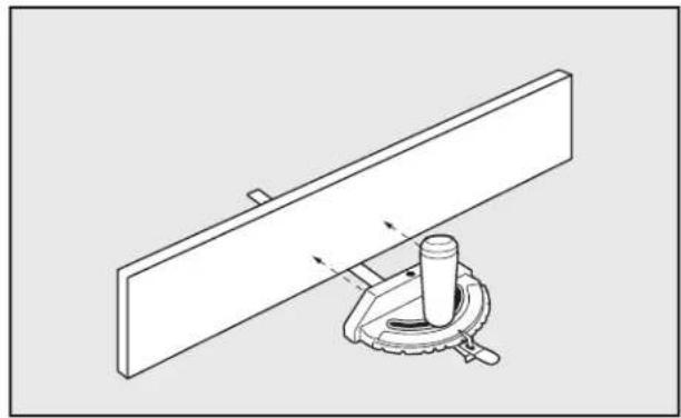
FIGURE 53
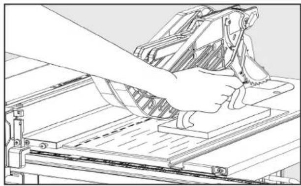
FIGURE 54

FIGURE 55
GROOVING AND RABBETING
Clamping a featherboard in front of the blade can increase safety during non-through cuts, like grooving and rabbeting, and through cuts. Use a featherboard to guide the workpiece against the table and fence when making non-through cuts such as rabbeting. A featherboard helps control the kickback.
CUTTING AIDS AND ACCESSORIES
FEATHERBOARD
Featherboards are used to KEEP the workpiece in contact with the fence and table see Figure 57, and help prevent kickback. Featherboards are especially useful when ripping narrow workpieces and for completing non-through cuts. The end is angled with a series of narrow slots to give a friction hold on the workpiece, It is locked in place on the table or fence with a c-clamps.
WARNING: To avoid binding between the workpiece and the blade, make sure a horizontal feather board presses ONLY on the uncut portion of the workpiece in front of the blade.
Dimensions for making a typical featherboard are shown in Figure 56. Make your featherboard from a straight piece of wood that is free of knots and cracks. Clamp featherboards to the fence and/or table so that the featherboard will hold the workpiece against the fence or table. Clamping a featherboard in front of the blade can increase safety during non-through cuts and through cuts.
- Select a solid piece of lumber approximately 3/4 inch thick, 2 1/2 inches wide and 12 inches long.
- Mark the center width on one end of stock. Miter width to 70^ (see "MITER CUT" section for information on miter cuts).
- Set rip fence to allow approximately a 1/4 inch "finger" to be cut in the stock.
- Feed stock ONLY to mark previously made at 6 inches.
- Turn saw off and allow blade to completely stop rotating before removing stock.
- Reset rip fence and cut spaced rips into workpiece to allow approximately 1/4 inch fingers and 1/8 inch spaces between fingers.
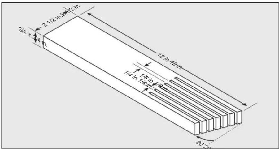
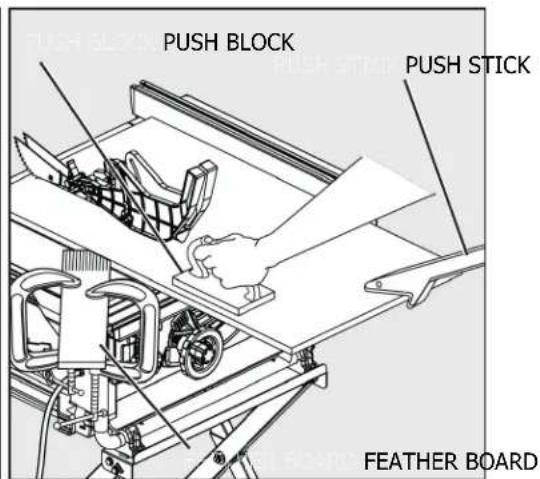
FIGURE 56 FIGURE 57
CUT OFF GAUGE
When crosscutting a number of pieces to the same length, you can clamp a block of wood A, in Figure 58, to the fence and use it as a cut-off gauge. The block A MUST be at least 3/4 inch (19mm) thick to prevent the cut off piece from binding between the blade and the fence. Once the cut-off length is determined, lock the fence and use the miter gauge to feed the workpiece into the blade.
CAUTION: ALWAYS position the cut-off gauge in front of the saw blade.
JIGS
Jigs may be created with a variety of special set-ups to control particular workpiece shapes for particular cuts. Guidance on how to make specialized jigs can be found in woodworking and carpentry websites and publications.
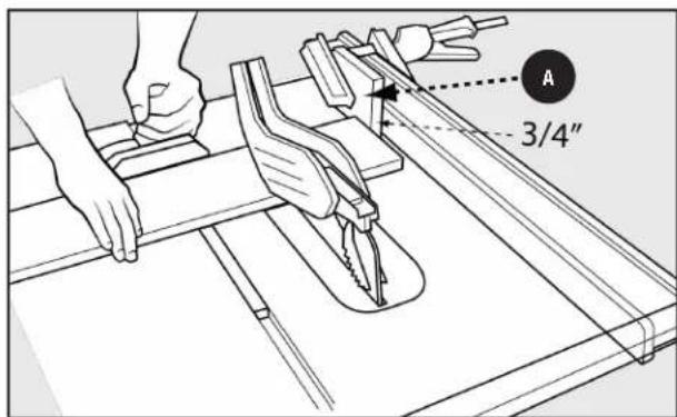
FIGURE 58
CAUTION: DO NOT attempt to create or use a jig unless you are thoroughly familiar with table saw safety. DO NOT use any jig that could result in pinching a kerf or jamming the workpiece between the jig and the blade. Incorrect setups may cause kickback which could result in serious injury.
MAINTENANCE
WARNING: To reduce the risk of injury, turn unit off and disconnect it from power source before cleaning or servicing, before installing and removing accessories, before adjusting and when making repairs. An accidental start-up can cause injury.
KEEP MACHINE CLEAN
Periodically blow out all air passages with dry compressed air. All plastic parts should be cleaned with a soft damp cloth. NEVER use solvents to clean plastic parts. They could possibly dissolve or otherwise damage the material.
WARNING: Wear certified safety equipment for eye, hearing and respiratory protection while using compressed air.
For best performance use a shop vacuum or blower to KEEP saw blade area, the dust collection system, the guarding system and rails free of saw dust and other debris.
WARNING: Wear certified safety equipment for eye, hearing and respiratory protection while using compressed air. WARNING: ALWAYS turn saw off and unplug from power source before making adjustments or performing maintenance.
Specific areas which require regular maintenance include:
RIVING KNIFE CLAMP PLATE: KEEP this area free of dust and debris buildup. Blow out area regularly with compressed air. NOTE: If the riving knife clamp can't move freely, have the saw serviced by authorized DELTA service center personnel. BEVEL GEARs: KEEP the bevel gears free of dust and debris buildup. Blow out area regularly with compressed air. Use a lithium-based multipurpose grease as needed on these gears.
CLEAN SAWDUST BUILDP OUT OF CABINET PERIODICALLY: NOTE: Debris can also be removed from the saw from below the throat plate, inside the dust port.
ACCESSIONS
A complete line of accessories is available from your DELTA® Supplier, DELTA® Factory Service Centers, and DELTA® Authorized Service Centers. Please visit our Web Site www.DeltaMachinery.com for an online catalog or for the name or your nearest supplier.
WARNING: Since accessories other than those offered by DELTA® have not been tested with this product, use of such accessories could be hazardous. For safest operation, only DELTA® recommended accessories should be used with this product.
TROUBLESHOOTING
For assistance with your machine, visit our website at www.DeltaMachinery.com for a list of service centers or call DELTA® Customer Service at (toll free) 1-800-223-7278 or email at Customercare@dpec-na.com.
FAILURE TO START
If your machine fails to start, check to make sure the prongs on the cord plug are making good contact in the receptacle, and check reset button on "GFI" receptacle (If applicable). Also, check for blown fuses or open circuit breakers in your power line.
| Question: Solution: | |
| How do you make the blade parallel to the miter slot? Reference Page 21. | |
| Can this unit be converted to 220 volt? No. | |
| What do I do if I have a problem with my Fence? Reference page 24. If the problem still exists, contact the Customer Care team by calling 1-800-223-7278 or emailing Customercare@dpec-na.com. | |
| What do I do if I have a problem with my Stand? Reference page 13. If the problem still exists, contact the Customer Care team by calling 1-800-223-7278 or emailing Customercare@dpec-na.com. | |
| What do I do if my unit has no power? Begin by checking the "POWER SOURCE" and "EXTENSION CORDS" sections on page 9 to ensure you are utilizing the machines power appropriately. If the problem continues, contact our Customer Care line at 1-800-223-7278 or emailing Customercare@dpec-na.com. | |
| How do I find my local repair center? | Contact our Customer Care team by calling 1-800-223-7278 or emailing us at Customercare@dpec-na.com. |
| How do I get Warranty work done on my product? | KEEP a copy of your receipt to present to our Service Center if any issues arise with your machine. |
PARTS, SERVICE OR WARRANTY ASSISTANCE
All DELTA® Machines and accessories are manufactured to high quality standards and are serviced by a network of an Authorized Service Centers. To obtain additional information regarding your product or to obtain parts, service, warranty assistance, or the location of the nearest service center, please call 1-800-223-7278 or email customercare@dpec-na.com.
FIVE YEAR LIMITED WARRANTY
- WHAT IS COVERED. Delta Power Equipment Corporation ("Company") will, at its option, repair or replace this product, if purchased at retail in the United States or Canada and the product, with normal use, has proven to be defective in workmanship or material, subject to the conditions stated in this Limited Warranty. This Limited Warranty covers only materials and labor. All transportation costs are Customer's responsibility.
- WARRANTY PERIOD. All warranty claims must be submitted within five years from the date of retail purchase. For all service parts and factory refurbished products, the warranty period is 180 days.
- HOW TO OBTAIN SERVICE. To obtain warranty service, you must return the defective product, at your expense, to a service center authorized by Company to perform warranty service (a "Company Authorized Service Center") within the applicable warranty period, together with acceptable proof of purchase, such as your original receipt bearing the date of purchase, or product registration number. Company reserves the right to restrict warranty claim service to the country where the purchase was made and/or to charge for the cost to export service parts or provide warranty service in a different country. For this purpose, on-line purchases are deemed made in the United States. For the location of your nearest Company Authorized Service Center, call Company's Customer Care Center at (800) 223-7278.
4. EXCLUSIONS.
- Company does not offer any warranty on products purchased in used or damaged condition.
- Company does not warrant any products purchased outside the United States or Canada.
Company will not be responsible for any damage that has resulted from normal wear, misuse, abuse or any repair or alteration made by anyone other than a Company Authorized Service Center or a designated representative of Company's Customer Care Center.
All IMPLIED WARRANTY ARE expressly limited to the warranty period identified above.
Company will not be liable for INCIDENTAL OR CONSEQUENTIAL damages.
This limited warranty is Company's sole warranty and sets forth the customer's exclusive remedy with respect to defective products; all other warranties, express or implied, whether of merchantability, fitness for purpose, or otherwise, are expressly disclaimed by Company, except as expressly stated in this warranty statement.
Some states do not allow the exclusion or limitation of incidental or consequential damages, or the limitation of implied warranties, so the above limitations or exclusions may not apply to you. This warranty gives you specific legal rights and you may have other rights which vary in certain states or provinces. For further details of warranty coverage and warranty repair information, call (800) 223-7278. Thank you for purchasing our product! Please maintain a copy of your proof of purchase/receipt for any potential warranty claims.
Latin America: This warranty does not apply to products sold in Latin America. For products sold in Latin America, call the local company or see website for warranty information.
REPLACEMENT PARTS
This power tool is provided with Type Y attachment power supply cord. If the replacement of the power supply cord is necessary, this has to be done by the manufacturer or his agent in order to avoid a safety hazard. Use only identical replacement parts. For a parts list or to order parts, visit our website at www.DeltaMachinery.com/support. You can also order parts from your nearest Authorized Warranty Service Center or by calling Technical Service Manager at 1-800-223-7278 to receive personalized support from one of our highly-trained representatives.
FREE WARNING LABEL REPLACEMENT
If your warning labels become illegible or are missing, call 1-800-223-7278 or email customercare@dpec-na.com for a free replacement.
SERVICE AND REPAIRS
All quality tools will eventually require servicing and/or replacement of parts. For information about Delta Power Equipment Corporation, its factory-owned branches, or to locate an Authorized Warranty Service Center, visit our website at www.DeltaMachinery.com/support or call Customer Care at 1-800-223-7278. All repairs made by our service centers are fully guaranteed against defective material and workmanship. We cannot guarantee repairs made or attempted by others. By calling this number you can also find answers to most frequently asked questions 24 hours/day.
You can also write to us for information at Delta Power Equipment Corporation, 2651 New Cut Road, Spartanburg, SC 29303
Attention: Technical Service Manager. Be sure to indicate all of the information shown on the nameplate of your saw (model number, type, serial number, date code, etc.).
TABLE DES MATIÈRES
CHARACTERISTIQUES 2
CONSIGNES IMPORTANTES DE SECURITE 4
SYMBOLES DE SECURITE - DÉFINITIONS 4
AVERTISSEMENTS DE SECURITE GENÉRAUX POUR
OUTILS ELECTRIQUES. 4
RÉGLES DE SECURITÉ DE LA SCIE CIRCULAIRE À TABLE ....6
TERMINOLOGIE 6
RÉGLES DE SECURITÉ GÉNÉRALES POUR LES
OUTILS ELECTRIQUES 8
PROTECTION DE LA LAME DE SCIE, CLIQUETS ANTI
RETOUR ET ASSEMBLAGE DE COUTEAUX DIVISEURS .8
REBONDS. 8
PROPOSITION 65 AVERTISSEMENT. 9
BRANCHEMENTS D'ALIMENTATION 9
SOURCE D'ALIMENTATION 9
DOUBLE ISOLATION 9
CONNEXION ELECTRIQUE 9
FICHES POLARISEES. 9
RALLONGES 9
DEBALLAGE. 10
CONTENU DE L'EMBALLAGE 10
CONTENU DES SACS DE MATÉRIEL 10
MONTAGE 12
OUTILS NÉCESSAIRES POUR LE
MONTAGE OU LES RÉGLAGES. 12
MONTAGE DU SUPPORT. 13
FIXATION DU SUPPORT A LA SCIE 14
INSTALLATION DU BOUTON DE RÉGLAGE DE HAUTEUR......15
INSTALLATION DE LA LAME 15
PLAQUE A GORGGE 16
DOIGTS ANTI-RETOUR ET PROTEGE-LAME. 17
INSTALLATION DE LA CLÔTURE. 18
RETRAIT DE LA BARRIERE 18
RANGEMENT 19
EFFECTUER DES RÉGLAGES 20
MISE A NIVEAU DE LA PLAQUE A GORGE 20
AJUSTER LA LAME PARALLELEMENT A
LA RAINURE DU GUIDE D'ONGLETS (TALON) 20
ÉQUERRAGE LA LAME VERTICALEMENT À LA TABLE .....................21
ASSISTANCE POUR PIECES, SERVICE OU GARANTIE....39
CHARACTERISTIQUES
SPECIFICATIONS
SOURCE D'ALIMENTATION
TENIR LA MACHINE PROPRE
©2023 Delta Power Equipment Corporation
DPEC007222
Rev:4
04/12/2023