
ShopMaster S26‑263LS - Saw DELTA - Free user manual and instructions
Find the device manual for free ShopMaster S26‑263LS DELTA in PDF.

| Product Type | Sliding Compound Miter Saw |
| Brand / Model | Delta ShopMaster S26-263LS |
| Power Supply | 120 V ~, 60 Hz, 15 A |
| Motor Power | 15 A (accessible brush motor) |
| No-Load Speed | 5,500 RPM |
| Blade Diameter | 10 in (254 mm) |
| Blade Arbor | 5/8 in (15.875 mm) |
| Max. Cutting Capacity (0°/0°) | 4 in thickness x 12 in width |
| Cutting Capacity (45°/0°) | 4 in x 8 in |
| Cutting Capacity (0°/45°) | 2 in x 12 in |
| Cutting Capacity (45°/45°) | 2 in x 8 in |
| Miter Range | 0° to 45° left and right (stops at 0°, 15°, 22.5°, 31.6°, 45°) |
| Bevel Range | 0° to 45° left |
| Net Weight | 29.5 lb (13.4 kg) |
| Insulation Type | Double insulation (no grounding required) |
| Electric Brake | Yes, stops blade quickly |
| Laser Guide | Yes, adjustable, AAA batteries (included) |
| Dust Collection System | Dust bag included |
| Horizontal Vise | Yes, included |
| Support Extensions | 2 pieces included |
| Blade Wrench | Integrated, with Phillips and hex screwdriver |
| Routine Maintenance | Clean with compressed air, check motor brushes quarterly |
| Warranty | 3 years limited, parts and labor |
Frequently Asked Questions - ShopMaster S26‑263LS DELTA
User questions about ShopMaster S26‑263LS DELTA
0 question about this device. Answer the ones you know or ask your own.
Ask a new question about this device
Download the instructions for your Saw in PDF format for free! Find your manual ShopMaster S26‑263LS - DELTA and take your electronic device back in hand. On this page are published all the documents necessary for the use of your device. ShopMaster S26‑263LS by DELTA.
USER MANUAL ShopMaster S26‑263LS DELTA
IMPORTANT SAFETY INSTRUCTIONS....2
GENERAL POWER TOOL SAFETY WARNINGS ....3
SAFETY INSTRUCTIONS FOR MITERE SAW.... 4
PROPOSITION 65 WARNING....5
POWER CONNECTIONS .... 5
FEATURES 6
UNPACKING AND ASSEMBLY....8
MOUNTING AND TRANSPORTATION....9
PREPARATIONS FOR TRANSPORTATION....9
BASE WITH CARRY HANDLES....9
MOUNTING A TABLE SAW TO A STABLE SURFACE..... 9
ASSEMBLY....10
SUPPORT EXTENSIONS .... 10
ATTACHING WORK CLAMP 10
INSTALL DUST COLLECTION BAG....10
INSTALL BATTERIES FOR LASER....11
PREPARING YOUR SAW FOR USE....11
INSTALL/REPLACE THE BLADE ....11
ALIGN THE BLADE TO THE TABLE....12
USING THE LASER GUIDE....13
OPERATION....14
POWER SWITCH LOCK-OUT 14
POWER SAFETY TOGGLE 14
TO SLIDE CUT....15
TIPS FOR CUTTING AND SUPPORTING WORKPIECE ..16
CUTTING WARPED MATERIAL....17
CLAMPING WIDE WORKPIECES....17
SUPPORTING LONG WORKPIECES ....18
ADJUSTMENTS....18
BEVEL PIVOT 19
LASER ADJUSTMENTS....19
DEPTH STOP ADJUSTMENT 20
MAINTENANCE 21
BRUSH REPLACEMENT....21
TROUBLE SHOOTING 21
ACCESSORIES....22
PARTS, SERVICES OR WARRANTY ASSISTANCE......22
FRENCH 23
SPANISH....46
IMPORTANT SAFETY INSTRUCTIONS
⚠ WARNING: REFULLY READ AND FOLLOW ALL WARNINGS AND INSTRUCTIONS ON YOUR PRODUCT AND IN THIS MANUAL. SAVE THIS MANUAL. MAKE SURE ALL USERS ARE FAMILIAR WITH ITS WARNINGS AND INSTRUCTIONS WHEN USING THE TOOL. Improper operation, maintenance or modification of tools or equipment could result in serious injury and/or property damage.

SAFETY LOGOS
This manual contains information that is important for you to know and understand. This information relates to protecting YOUR SAFETY and PREVENTING EQUIPMENT PROBLEMS. To help you recognize this information, we use the symbols below. Please read the manual and pay attention to these sections.
▲DANGER: Indicates an imminently hazardous situation which, if not avoided, will result in death or serious injury.
⚠ WARNING: Indicates a potentially hazardous situation which, if not avoided, could result in death or serious injury.
▲CAUTION: Indicates a potentially hazardous situation which, if not avoided, may result in minor or moderate injury.
CAUTION: Used without the safety alert symbol indicates potentially hazardous situation which, if not avoided, may result in property damage.

Do not expose power tools to rain or wet conditions.
Additional information regarding the safe and proper operation of this tool is available from the following sources:
• Power Tool Institute, 1300 Sumner Avenue, Cleveland, OH 44115-2851 or on-line at www.powertoolinstitute.com
• National Safety Council, 1121 Spring Lake Drive, Itasca, IL 60143-3201
- American National Standards Institute, 25 West 43rd Street, 4 floor, New York, NY 10036 www.ansi.org - ANSI 01.1 Safety Requirements for Woodworking Machines
• U.S. Department of Labor regulations www.osha.gov
GENERAL POWER TOOL SAFETY WARNINGS
WARNING Read all safety warnings, instructions, illustrations and specifications provided with this power tool. Failure to follow all instructions listed below may result in electric shock, fire and/or serious injury.
Save all warnings and instructions for future reference.
The term “power tool” in the warnings refers to your mains-operated (corded) power tool or BATTERY-operated (cordless) power tool.
1) Work area safety
a) Keep work area clean and well lit. Cluttered or dark areas invite accidents.
b) Do not operate power tools in explosive atmospheres, such as in the presence of flammable liquids, gases or dust. Power tools create sparks which may ignite the dust or fumes.
c) Keep children and bystanders away while operating a power tool. Distractions can cause you to lose control.
2) Electrical safety
a) Power tool plugs must match the outlet. Never modify the plug in any way. Do not use any adapter plugs with earthed (grounded) power tools. Unmodified plugs and matching outlets will reduce risk of electric shock.
b) Avoid body contact with earthed or grounded surfaces, such as pipes, radiators, ranges and refrigerators. There is an increased risk of electric shock if your body is earthed or grounded.
c) Do not expose power tools to rain or wet conditions. Water entering a power tool will increase the risk of electric shock.
d) Do not abuse the cord. Never use the cord for carrying, pulling or unplugging the power tool. Keep cord away from heat, oil, sharp edges or moving parts. Damaged or entangled cords increase the risk of electric shock.
e) When operating a power tool outdoors, use an extension cord suitable for outdoor use. Use of a cord suitable for outdoor use reduces the risk of electric shock.
f) If operating a power tool in a damp location is unavoidable, use a RESIDUAL CURRENT DEVICE (RED) protected supply. Use of an RCD reduces the risk of electric shock.
3) Personal safety
a) Stay alert, watch what you are doing and use common sense when operating a power tool. Do not use a power tool while you are tired or under the influence of drugs, alcohol or medication. A moment of inattention while operating power tools may result in serious personal injury.
b) Use personal protective equipment. Always wear eye protection. Protective equipment such as dust mask, non-skid safety shoes, hard hat, or hearing protection used for appropriate conditions will reduce personal injuries.
c) Prevent unintentional starting. Ensure the switch is in the off-position before connecting to power source and/or BATTERY pack picking up, or carrying the tool. Carrying power tools with your finger on the switch or energising power tools that have the switch on invites accidents.
d) Remove any adjusting key or wrench before turning the power tool on. A wrench or a key left attached to a rotating part of the power tool may result in personal injury.
e) Do not overreach. Keep proper footing and balance at all times. This enables better control of the power tool in unexpected situations.
f) Dress properly. Do not wear loose clothing or jewellery. Keep your hair, clothing and gloves away from moving parts. Loose clothes, jewellery or long hair can be caught in moving parts.
g) If devices are provided for the connection of dust extraction and collection facilities, ensure these are connected and properly used. Use of dust collection can reduce dust-related hazards.
h) Do not let familiarity gained from frequent use of tools allow you to become complacent and ignore tool safety principles. A careless action can cause severe injury within a fraction of a second.
4) Power tool use and care
a) Do not force the power tool. Use the correct power tool for your application. The correct power tool will do the job better and safer at the rate for which it was designed.
b) Do not use the power tool if the switch does not turn it on and off. Any power tool that cannot be controlled with the switch is dangerous and must be repaired.
c) Disconnect the plug from the power source and/or remove the BATTERY pack if detachable, from the power tool before making any adjustments, changing accessories, or storing power tools. Such preventive safety measures reduce the risk of starting the power tool accidentally.
d) Store idle power tools out of the reach of children and do not allow persons unfamiliar with the power tool or these instructions to operate the power tool. Power tools are dangerous in the hands of untrained users.
e) Maintain power tools and accessories. Check for misalignment or binding of moving parts, breakage of parts and any other condition that may affect the power tool's operation. If damaged, have the power tool repaired before use. Many accidents are caused by poorly maintained power tools.
f) Keep cutting tools sharp and clean. Properly maintained cutting tools with sharp cutting edges are less likely to bind and are easier to control.
g) Use the power tool, accessories and tool bits etc. in accordance with these instructions, taking into account the working conditions and the work to be performed. Use of the power tool for operations different from those intended could result in a hazardous situation.
h) Keep handles and grasping surfaces dry, clean and free from oil and grease. Slippery handles and grasping surfaces do not allow for safe handling and control of the tool in unexpected situations.
GENERAL POWER TOOL SAFETY RULES
5) Service
a) Have your power tool serviced by a qualified repair person using only identical replacement parts. This will ensure that the safety of the power tool is maintained.
SAFETY INSTRUCTIONS FOR MITRE SAWS
a) Mitre saws are intended to cut wood or wood-like products, they cannot be used with abrasive cut-off wheels for cutting ferrous material such as bars, rods, studs, etc. Abrasive dust causes moving parts such as the lower guard to jam. Sparks from abrasive cutting will burn the lower guard, the kerf insert and other plastic parts.
b) Use clamps to support the workpiece whenever possible. If supporting the workpiece by hand, you must always keep your hand at least 100 mm from either side of the saw blade. Do not use this saw to cut pieces that are too small to be securely clamped or held by hand. If your hand is placed too close to the saw blade, there is an increased risk of injury from blade contact.
c) The workpiece must be stationary and clamped or held against both the fence and the table. Do not feed the workpiece into the blade or cut "freehand" in any way. Unrestrained or moving workpieces could be thrown at high speeds, causing injury.
d) Push the saw through the workpiece. Do not pull the saw through the workpiece. To make a cut, raise the saw head and pull it out over the workpiece without cutting, start the motor, press the saw head down and push the saw through the workpiece. Cutting on the pull stroke is likely to cause the saw blade to climb on top of the workpiece and violently throw the blade assembly towards the operator.
e) Never cross your hand over the intended line of cutting either in front or behind the saw blade. Supporting the workpiece “cross handed” i.e. holding the workpiece to the right of the saw blade with your left hand or vice versa is very dangerous.
f) Do not reach behind the fence with either hand closer than 100 mm from either side of the saw blade, to remove wood scraps, or for any other reason while the blade is spinning. The proximity of the spinning saw blade to your hand may not be obvious and you may be seriously injured.
g) Inspect your workpiece before cutting. If the workpiece is bowed or warped, clamp it with the outside bowed face toward the fence. Always make certain that there is no gap between the workpiece, fence and table along the line of the cut. Bent or warped workpieces can twist or shift and may cause binding on the spinning saw blade while cutting. There should be no nails or foreign objects in the workpiece.
h) Do not use the saw until the table is clear of all tools, wood scraps, etc., except for the workpiece. Small debris or loose pieces of wood or other objects that contact the revolving blade can be thrown with high speed.
i) Cut only one workpiece at a time. Stacked multiple workpieces cannot be adequately clamped or braced and may bind on the blade or shift during cutting.
j) Ensure the mitre saw is mounted or placed on a level, firm work surface before use. A level and firm work surface reduces the risk of the mitre saw becoming unstable.
k) Plan your work. Every time you change the bevel or mitre angle setting, make sure the adjustable fence is set correctly to support the workpiece and will not interfere with the blade or the guarding system. Without turning the tool "ON" and with no workpiece on the table, move the saw blade through a complete simulated cut to assure there will be no interference or danger of cutting the fence.
1) Provide adequate support such as table extensions, saw horses, etc. for a workpiece that is wider or longer than the table top. Workpieces longer or wider than the mitre saw table can tip if not securely supported. If the cut-off piece or workpiece tips, it can lift the lower guard or be thrown by the spinning blade.
m) Do not use another person as a substitute for a table extension or as additional support. Unstable support for the workpiece can cause the blade to bind or the workpiece to shift during the cutting operation pulling you and the helper into the spinning blade.
n) The cut-off piece must not be jammed or pressed by any means against the spinning saw blade. If confined, i.e. using length stops, the cut-off piece could get wedged against the blade and thrown violently.
o) Always use a clamp or a fixture designed to properly support round material such as rods or tubing. Rods have a tendency to roll while being cut, causing the blade to "bite" and pull the work with your hand into the blade.
p) Let the blade reach full speed before contacting the workpiece. This will reduce the risk of the workpiece being thrown
q) If the workpiece or blade becomes jammed, turn the mitre saw off. Wait for all moving parts to stop and disconnect the plug from the power source and/or remove the battery pack. Then work to free the jammed material. Continued sawing with a jammed workpiece could cause loss of control or damage to the mitre saw.
r) After finishing the cut, release the switch, hold the saw head down and wait for the blade to stop before removing the cut-off piece. Reaching with your hand near the coasting blade is dangerous.
s) Hold the handle, firmly when making an incomplete cut or when releasing the switch before the saw head is completely in the down position. The braking action of the saw may cause the saw head to be suddenly pulled downward, causing a risk of injury.
PROPOSITION 65 WARNING:
WARNING:
Some dust created by power sanding, sawing, grinding, drilling, and other construction activities contains chemicals known to the state of California to cause cancer, birth defects or other reproductive harm. Some examples of these chemicals are:
- Lead from lead-based paints
- Crystalline silica from bricks and cement and other masonry products
- Arsenic and chromium from chemically-treated lumber
Your risk from these exposures varies, depending on how often you do this type of work. To reduce your exposure to these chemicals: work in a well-ventilated area and work with approved safety equipment, such as dust masks that are specifically designed to filter out microscopic particles.
SAVE THESE INSTRUCTIONS.
Refer to them often and use them to instruct others.
If tool is loaned to someone, also loan them these instructions.
POWER CONNECTIONS
A separate electrical circuit should be used for your machines. This circuit should not be less than #12 wire and should be protected with a 15 Amp time lag fuse. If an extension cord is used, use only 3-wire extension cords which have a 3-prong grounding type plugs. Before connecting the machine to the power line make sure the switch(s) is in the "OFF" position and be sure that the electric current is of the same characteristics as indicated on the machine. All line connections should make good contact. Running on low voltage will damage the machine.
DANGER:
DO NOT EXPOSE THE MACHINE TO RAIN OR OPERATE THE MACHINE IN DAMP LOCATIONS.
Your machine is wired for 120 volts, 60 HZ alternating current. Before connecting the machine to the power source, make sure the switch is in the "OFF" position.
DOUBLE INSULATION
This machine is double insulated. Double insulation is a concept in safety in electric power tools, which eliminates the need for the usual three-wire grounded power cord. All exposed metal parts are isolated from the internal metal motor components with protecting insulation. Double insulated tools do not need to be grounded.
WARNING:
The double insulated system is designed to protect the user from shock resulting from a break in the tool's internal insulation. However, it is important to observe normal safety precautions to avoid electrical shock.
NOTE: Servicing of a tool with double insulation requires extreme care and knowledge of the system and should be performed by an authorized DELTA® agent. For service, we suggest you return the tool to the nearest authorized DELTA® agent for repair. Always use identical replacement parts when servicing.
POWER CONNECTIONS
ELECTRICAL CONNECTION
This tool has a precision-built electric motor. It should be connected to a POWER SUPPLY THAT IS 120 VOLTS, 60 HZ, AC ONLY (NORMAL HOUSEHOLD CURRENT). Do not operate this tool on direct current (DC). A substantial voltage drop will cause a loss of power and the motor will overheat. If the tool does not operate when plugged into an outlet, double-check the power supply.
POLARIZED PLUGS
To reduce the risk of electric shock, this equipment has a polarized plug (one blade is wider than the other). This plug will fit in a polarized plug only one way. If the plug does not fully fit in the outlet reverse the plug. If it still does not fit, contact a qualified electrician to install the proper outlet. Do not change the plug in any way.
EXTENSION CORDS
When using a power tool at a considerable distance from a power source, be sure to use an extension cord that has the capacity to handle the current the tool will draw. An undersized cord will cause a drop in line voltage, resulting in overheating and loss of power. Use the chart to determine the minimum wire size required in an extension cord. Only round jacketed cords listed by Underwriter's Laboratories (UL) should be used. When working outdoors with a tool, use an extension cord that is designed for outside use. This type of cord is designated with a "WA" on the cord's jacket.
Before using any extension cord, inspect it for loose or exposed wires and cut or worn insulation.
⚠ WARNING: Keep the extension cord clear of the work area. Position the cord so that it will not get caught on lumber, tools or other obstructions while you are working with a power tool. Failure to do so can result in serious personal injury. Check extension cords before each use. If damaged replace immediately. Never use tool with a damaged cord, since touching the damaged area could cause electrical shock resulting in serious injury.
| ** Ampere rating (on total data label)12A- 16A | |
| Cord Length Wire Size | |
| 25' 14 AWG | |
| 50' 12 AWG | |
| ** Used on 12 gauge - 20 amp0 circuitNOTE: AWG = American Wire Gauge | |
FEATURES
PRODUCT SPECIFICATIONS
| Cutting Capacity(Maximum nominal lumber sizes) | 0° Mitre/0° Bevel: 4" x 12"45° Mitre/ 0° Bevel: 4" x 8"0° Mitre/45° Bevel: 2" x 12"45° Mitre/45° Bevel: 2" x 8" |
| Net Weight | 29.5 lbs |
| Input | 120 V~, 60hz, 15 Amps |
| Blade Arbor | 5/8" |
| Blade Diameter | 10" |
| No Load Speed | 5,500 r/min (RPM) |
FEATURES
A. Motor
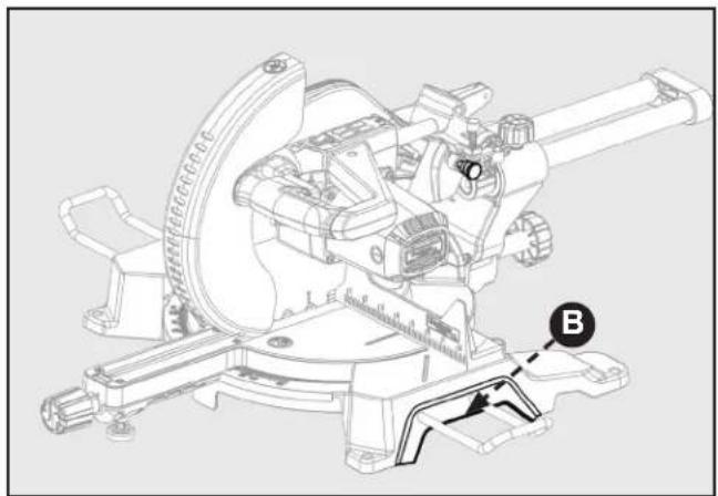
B. Fence
C. Throat Plate
D. Mitre Lock Knob
E. Support Extensions
F. Mitre Scale with Positive Stops
G. Horizontal Work Clamp
H. Base with Carry Handles
I. Mounting Holes
J. On-Board Wrench
K. Work Table
L. Bevel Lock Knob
M. Dust Bag
N. Upper and Lower Blade Guards
O. Blade (not visible)
P. Saw Head Handle
Q. Spindle lock
R. Slide Lock Knob
S. Electric Brake (not shown)
T. Laser
U. Power Switch (not visible)
V. Power Safety Toggle

FIGURE 1
KNOW YOUR COMPOUND MITRE SAW
Refer to Figure 1.
Using this tool safely requires that you understand the information provided in this operator's manual, as well as the project you are attempting. Before using this product, familiarize yourself with all operating features and safety rules.
A. 15-AMP MOTOR: This tool features a powerful 15-amp motor with all ball bearings and externally accessible brushes for ease of servicing.
B. FENCE: The mitre fence supports the workpiece when making all cuts.
C. THROAT PLATE: The throat plate supports the workpiece and provides a safe working surface.
D. MITRE LOCK: The mitre lock knob securely locks the saw at desired mitre angles.
E. SUPPORT EXTENSIONS: Use these to help support large pieces when necessary.
F. MITRE SCALE WITH POSITIVE STOPS: Positive stops have been provided at 0°, 15°, 22-1/2°, 31.6°, and 45°. The blade stops have been provided on both the left and right side of the mitre table.
G. HORIZONTAL WORK CLAMP: The horizontal work clamp helps to position and secure the workpiece
to the fence, ensuring safer operation and more accurate cuts.
H. BASE WITH CARRY HANDLES: Supports the tool and features mounting holes. Use the carry handles which are designed into the base for safe and easy transportation of the saw.
I. MOUNTING HOLES: Enable you to securely mount the tool to a stable surface.
J. BLADE WRENCH STORAGE: The included blade wrench features a Phillips screwdriver at one end and a hex key at the other. Use the hex key when installing or removing blade and the Phillips screwdriver when removing or loosening screws. When not in use, the wrench can be stored in the base of the saw.
K. WORK TABLE: Sturdy, large die-cast aluminum work table provides a level and sturdy work surface.
L. BEVEL LOCK: the bevel lock knob secures the saw at the desired angle for bevel cuts. There are positive stop screws on each side of the saw arm for making fine adjustments at 0° and 45°.
M. DUST COLLECTION BAG: The included dust bag attaches and detached quickly with the integrated clamp for easy cleaning.
FEATURES
N. UPPER AND LOWER BLADE GUARDS: The lower blade guard is made of shock-resistant, see-through plastic that provides protection from each side of the blade. It automatically retracts over the upper blade guard as the saw is lowered into the workpiece.
O. 10-INCH BLADE: A 10 in. blade is included with the compound mitre saw. It will cut materials up to 3-1/2 in. thick or 12 in. wide, depending upon the angle at which the cut is being made.
P. SAW HEAD HANDLE: Use this handle to perform cuts as instructed in the operation section of this manual. This handle also includes the power switch for activating the saw blade.
Q. SPINDLE LOCK BUTTON: The spindle lock button locks the spindle preventing the blade from rotating while removing or installing the blade screw.
R. SLIDE LOCK: This allows head to move front to rear for cutting wide material up to 12" wide
S. ELECTRIC BRAKE: An electric brake has been
provided to more quickly stop blade rotation after the switch is released. (not shown)
T. LASER: For more accurate cuts, a laser is included with your mitre saw. When used properly, the laser makes accurate, precision cutting simple and easy.
U. POWER SWITCH: The saw blade is activated by an easy-to-use switch. When not in use the saw should be disconnected from the power supply and switch locked in the off position using a padlock (not included) inserted through the hole in the switch trigger. A lock with a long shackle up to 5/16 in. diameter may be used. The padlock and key should be stored in separate locations.
V. POWER SAFETY TOGGLE: Reduces safety risk for unauthorized users.
UNPACKING AND ASSEMBLY
Check shipping carton and machine for damage before unpacking. Carefully remove packaging materials, parts and machine from shipping carton. Always check for and remove protective shipping materials around motor and moving parts. Lay out all parts on a clean work surface.
Compare the items to inventory figures, verify that all items are accounted for before discarding the shipping carton. Report any missing or damaged parts, please call Company's Customer Care Center at 800-223-7278. Prior to tool assembly and use, read this manual to thoroughly familiarize yourself with proper assembly, maintenance and safety procedures.
If any parts are missing, do not attempt to plug in the power cord and turn the power on. The saw should only be energized after all parts have been located and correctly assembled.
natural_image
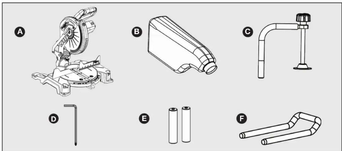
Illustration of six different mechanical components labeled A through F, including a motor, housing, and tubing (no text or symbols beyond labels)FIGURE 2
CONTENT DESCRIPTION (QTY)
A. SHOPMASTER #S26-263L 10-inch Sliding Compound Mitre Saw
B. Dust Collection Bag (1)
C. Horizontal Work Clamp (1)
D. Blade Wrench (1)
E. AAA Batteries (2)
F. Support Extensions (2)
MOUNTING AND TRANSPORTATION
WARNING:
WARNING: Before moving/transporting your saw it is important to make sure all of the following steps have been followed to ensure a safe condition for transportation. Failure to do so can result in serious personal injury.
WARNING:
• Always turn the power off and unplug saw before transporting.
- Secure power cord to avoid any snags or hang ups during transportation.
• Always lift using the strength of your legs to lift saw; never use your back muscles to lift saw.
- Do not use power On/Off switch handle or power cord to lift your saw.
• Always place the saw onto a stable and level surface with clearance for handling and maneuvering.
PREPARATIONS FOR TRANSPORTATION
- The saw is shipped with the arm secured in the down position as shown in Figure 3. To release the arm, push it down, cut the plastic tie and release the lock pin (A).
- Lock pin (A) is for storage and transport only. Saw is not to be locked in down position during cuts.
- Inspect the tool carefully to make sure no damage occurred during shipping.
- Do not discard the packaging material until you have carefully inspected and satisfactorily operated the tool.
WARNING:
WARNING: Saw Head lock pin is for storage and transport only. This saw should never be locked in the down position while making cuts.
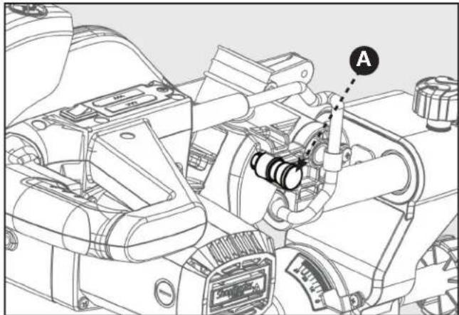
FIGURE 3
BASE WITH CARRY HANDLES
Use the carry handles which are designed into the base for safe and easy transportation of the saw. Shown in Fig. 4.
natural_image
Technical line drawing of a mechanical gun or weapon system with labeled component B (no text or symbols beyond label)FIGURE 4
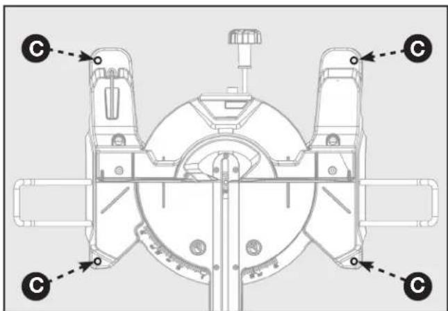
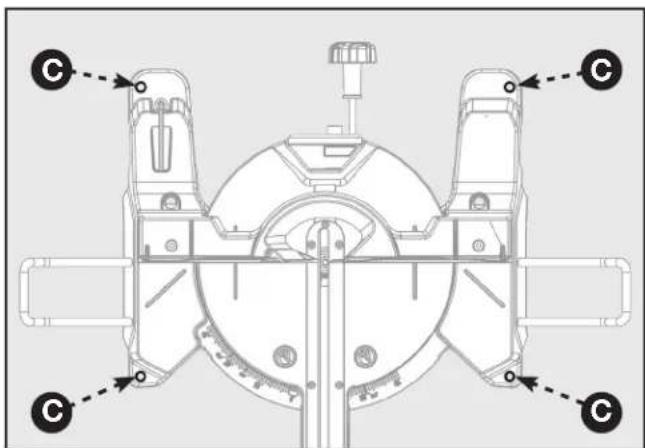
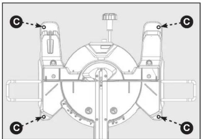
MOUNTING THE SAW TO A STABLE SURFACE
WARNING:
To ensure safe and accurate operation, this saw should be mounted to a stable
and level surface such as a workbench. To mount the tool to a stable surface, refer to Figure 5 and do the following:
- Locate the four mounting holes in the base of the saw (C).
- Secure the tool to the mounting surface using 3/8" diameter machine bolts, lock washers, and hex nuts (not included). Make sure the bolts are long enough to accommodate the saw base, lock washers, hex nuts, and the thickness of the workbench.
- Tighten all four bolts securely.
- Check to make sure that the saw is secure before operation.
natural_image
Technical line drawing of a mechanical assembly with no visible text or symbolsFIGURE 5
ASSEMBLY
WARNING:
- Do not attempt to modify this tool or create accessories not recommended for use with this tool. Any such alteration or modification is misuse and could result in a hazardous condition.
- Do not connect to power supply until assembly is complete. Failure to comply could result in accidental starting.
- Do not start the mitre saw without checking for interference between the blade and the mitre fence. Damage could result to the blade if it strikes the mitre fence during operation of the saw.
- The saw can tip over if the saw head is released suddenly and the saw is not secured to a work surface. ALWAYS secure this saw to a stable work surface before any use.
- If any parts are damaged or missing do not operate this tool until the parts are replaced. Please call Customer Care Center at 800-223-7278, for instructions.
SUPPORT EXTENSIONS
See Figure 6.
Table extensions have been provided for both the left and right side of the saw.
To install table extensions:
- Insert the ends of extension (A) into holes in the sides of the base (B).
- Thread Hex-Socket Cap Screw (C) into the end of extension (A). Tighten screw.
- Repeat for other extension.
- WARNING: Always fix and use workpiece support extensions during operation.
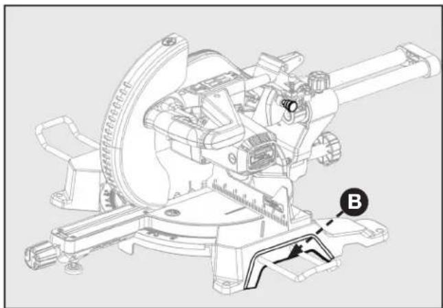
ATTACHING WORK CLAMP
The horizontal work clamp secures the workpiece to the fence to provide more stability and keeps the workpiece from creeping toward the saw blade. Depending on the cutting operation and the size of the workpiece, it may be preferable to use a C-clamp instead of the work clamp to secure the workpiece to the mitre table prior to making the cut.
To install the horizontal work clamp, see Figure 7 and do the following:
- Place the clamp shaft (D) in either hole (E) on the mitre table base.
- Rotate the knob (F) on the clamp clockwise to move it in or counter clockwise to move it out as needed.
INSTALL DUST COLLECTION BAG
The tool includes a dust collection bag that attached over the exhaust port on the upper blade guard. To install, slide the plastic collar (G) of the dust bag onto the dust port (H). See Figure 8.
NOTE: To remove the dust bag for emptying, simply reverse the above procedure.
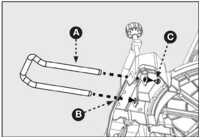
FIGURE 6
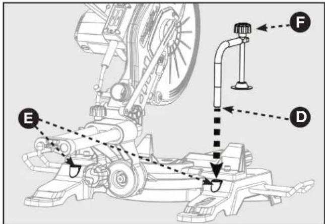
FIGURE 7
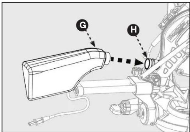
FIGURE 8
ASSEMBLY
INSTALL BATTERIES FOR LASER
- The battery compartment (A) is located in the control arm on the rear of the saw. See Figure 9.
- Using the Phillips end of the supplied blade wrench, remove the screw (B) securing the compartment cover and lift off the cover.
- Install two AAA batteries (supplied) as shown on the diagram in the compartment.
- Replace the cover and secure with the screw.
▲DANGER: Laser radiation. Avoid direct eye contact with light source.
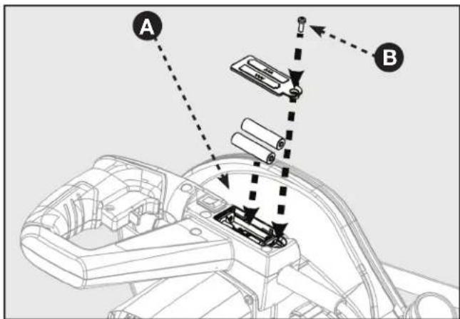
FIGURE 9
PREPARING YOUR SAW FOR USE
INSTALL/REPLACE THE BLADE
WARNING:
According to the markings on the saw a 10-inch blade is the maximum blade
capacity of the saw. Larger blades will come in contact with the blade guards. Only use blades which are rated for at least 5,500 RPM or higher. Only use blades with a maximum kerf width of 2.7mm or less.
- Make sure the saw is unplugged.
- Raise the saw arm to the full upright position.
- In Figure 10, Rotate the lower blade guard (C) up. Slightly loosen the blade bolt cover screw (D) until you can move the blade bolt cover (E) up to expose the blade bolt (F).
Refer to Figure 11. - Press the spindle lock button (G).
- If replacing the blade, carefully rotate the old blade until the spindle locks in place.
- Using the supplied blade wrench, remove the blade bolt (F) by turning it clockwise.
NOTE: The blade bolt has left-hand threads.
- Remove only the outer blade washer (H) and the blade (I), leaving the inner blade washer on the spindle.
WARNING:
If inner blade washer has been removed, replace it before placing blade on spindle.
Failure to do so could cause an accident since blade will not tighten properly.
- Carefully fit saw blade inside the lower blade guard and guide it onto spindle, ensuring the teeth of the blade are facing down at the front of the saw.
- Align the double "D" flats on the blade washer with the flats on the spindle and fit the washer onto the spindle.
- Lock the spindle by depressing the spindle lock button. Replace blade bolt, remembering to thread it counter clockwise. Tighten blade bolt securely.
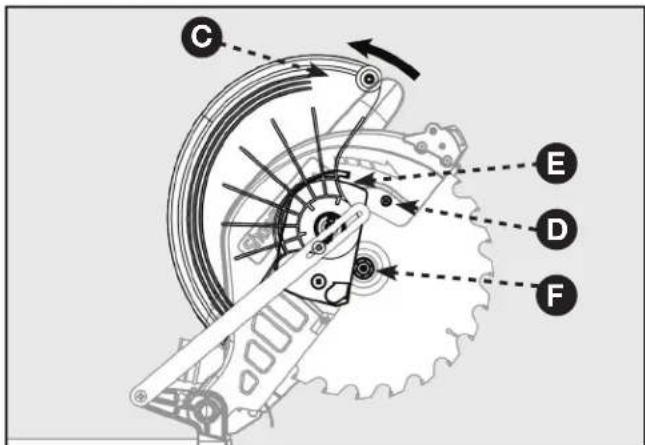
FIGURE 10
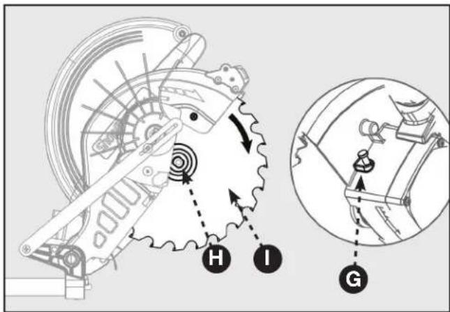
FIGURE 11
⚠ WARNING: Always install the blade with the blade teeth and the arrow on the side of the blade pointing down at the front of the saw. The direction of the blade rotation is also stamped with an arrow on the upper blade guard.
PREPARING YOUR SAW FOR USE
- Replace the blade bolt cover and tighten blade bolt cover screw securely. Lower blade guard.
- Raise and lower the saw arm to ensure that the arm and blade guard move freely.
WARNING:
Make sure the spindle lock button is not engaged before reconnecting saw to power source. Never engage spindle lock button when blade is rotating.
NOTE: Some illustrations in this manual indicate only portions of the saw. This is done in order to more clearly show key areas and components of the saw. Never operate the saw without all guards securely in place and in good operating condition.
ALIGN THE BLADE TO THE TABLE
Refer to Figure 12.
- Unplug the saw
- Lower the saw arm all the way down to the transport position and engage the lock pin to hold it in place.
- Rotate the mitre lock handle (A). Position the table so that the mitre scale indicator (B) reads 0°.
- Rotate the mitre lock handle to the locked position so that the table will not move.
- Loosen bevel lock knob (D) and adjust the angle of saw arm so that the bevel scale indicator (C) reads 0^ . This positions the blade at 90^ to the table.
- Securely tighten bevel lock knob.
- Place a combination square (E) against the table and the face of the saw blade (F).
NOTE: Make sure that the square contacts the flat part of the saw blade, not the blade teeth.
-
Rotate the blade by hand and check the blade-to-table alignment at several points.
-
The edge of the square and the saw blade should be parallel as shown in Figure 13.
-
If the top or bottom of the blade face is not flush with the square, refer to Figure 14 below and perform the following steps.
-
Loosen bevel lock knob (G).
-
Adjust positive stop adjustment screw (not shown) to bring saw blade into alignment with the square. See "Positive Stop Screw" in the Adjustment section.
-
Re-tighten bevel lock knob. Recheck blade-to-blade alignment.
NOTE: The above procedure can be used to check alignment of the blade to the mitre table at both 0° and 45° angles.
The saw has two scale indicators, one on the bevel scale and one on the mitre scale. After squaring adjustments have been made, it may be necessary to loosen the indicator screws and reset them to zero.
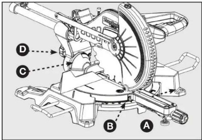
FIGURE 12
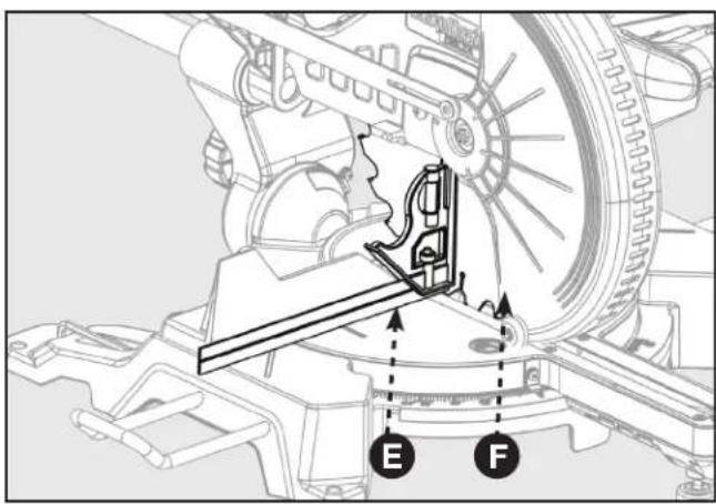
FIGURE 13

FIGURE 14
PREPARING YOUR SAW FOR USE
USING THE LASER GUIDE
Refer to Figure 15.
When the laser guide switch is turned on it projects a red line onto the work surface enabling you to see your cut before you make it. To ensure a true and straight cut:
- Make sure the saw is unplugged.
- Draw a line on the workpiece where you plan to cut.
- Flip the laser switch (A) on the "ON" position.
- The red line (B) indicates the path of the blade.
- Align the laser line and the mark with the blade at the uppermost position.
- Once both lines are in alignment, do not move the workpiece.
- Plug the saw into the power source.
- Make several practice cuts on different styles and thickness of material.
- Repeat the steps above is necessary.
TO REMOVE YOUR MARK:
Position the laser line near the left edge of your mark on the work surface in order to cut the mark.
TO CUT ON YOUR MARK:
Position the laser line near or over your mark on the work surface in order to cut the mark.
TO CUT WITHOUT REMOVING YOUR MARK:
Position the laser line near the right edge of your mark on the work surface in order to leave the mark,
After you have become familiar with using the laser guide, you will be able to remove, cut, or leave your mark on the work surface. Practice will teach you the correct position for aligning the laser line with your mark.
FREE WARNING LABEL REPLACEMENT
If your warning labels become illegible or are missing, user shall remake the label according to copy on manual and attach on the same location or call 1-800-223-7278 for a free replacement.
During operation and maintenance, human access to laser radiation in excess of the accessible emission limit is possible, so it should avoid direct eye exposure of laser radiation.
CAUTION:
Complies with 21 CFR 1040.10 and 1040.11 Use of controls or adjustments or performance of procedures other than those specified herein may result in hazardous radiation exposure.
CAUTION:
Metal instruments can cause a laser reflector. During operation and maintenance should avoid direct exposure in these instruments, as far as possible not to use reflective instruments. Action should be avoided with watches, necklaces, bracelets, it can be reflected laser accessories.
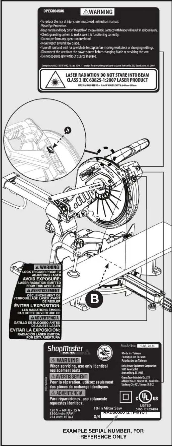
FIGURE 15
OPERATION
WARNING:
Do not allow familiarity with tools to make you careless. Remember that a careless fraction of a second is sufficient enough to inflict serious personal injury.
- Always wear eye protection with side shields and marked to comply with ANSI Z87.1 Failure to do so could result in objects being thrown into your eyes, resulting in possible serious personal injury.
- Do not use any attachments or accessories not recommended by the manufacturer of this tool. The use of attachments or accessories not recommended can result in serious personal injury.
- Before starting any cutting operation, clamp or bolt the compound mitre saw to a workbench. Never operate the mitre saw on the floor or in a crouched position. Failure to heed this warning can result in serious personal injury.
- To avoid serious personal injury, always tighten the mitre lock handle and bevel lock knob securely before making a cut. Failure to do so could result in movement of the control arm or mitre table while making a cut.
- To avoid serious personal injury, keep hands outside the no hands zone, at least 3 in. from blade. Never perform any cutting operation freehand (without holding workpiece against the fence). The blade could grab the workpiece if it slips or twists.
- When using a work clamp or C-clamp to secure the workpiece, clamp workpiece on one side of the blade only. The workpiece must remain free on one side of the blade to prevent the blade from binding in workpiece. The workpiece binding the blade will cause motor stalling and kickback. This situation could cause an accident resulting in serious personal injury.
- NEVER move the workpiece or make adjustment to any cutting angle while the saw is running and the blade is rotating. Any slip can result in contact with the blade causing serious personal injury.
- When cutting, do not force the blade against the workpiece. Forcing the blade will cause a drop in motor RPM and increase the risk of overheating the saw blade tips.
You may use this tool for the following purposes:
- Bevel cutting and compound cutting for crown moldings, etc.
• Cross cutting wood
• Cross cutting for moldings, door casings, picture frames, etc.
NOTE: This saw is for cutting wood. The blade provided is acceptable for wood cutting only.
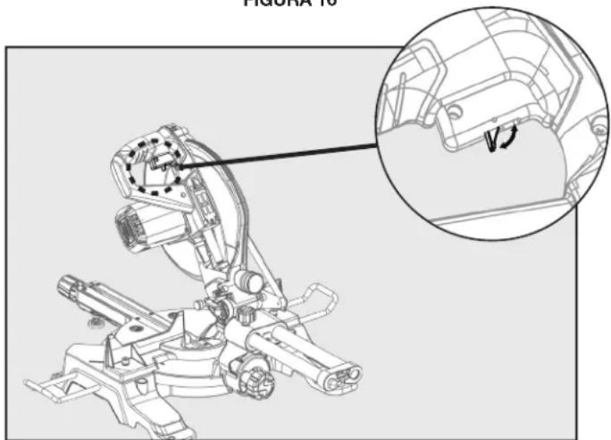
POWER SWITCH LOCK-OUT
To prevent any unauthorized person from operating this saw, a padlock (not included) should be installed into the Lock Hole located on the power switch, as shown in Figure 16. Be sure padlock is fully closed and locked before leaving this saw unattended.
WARNING:
Always disconnect the power supply before installing or removing a lock onto the power switch. Failure to do so could cause the power switch to engage by accident, resulting in serious injury.
POWER SAFETY TOGGLE
In order to turn the saw motor on, you must first engage the power safety toggle located on the power switch handle as shown in figure 17.
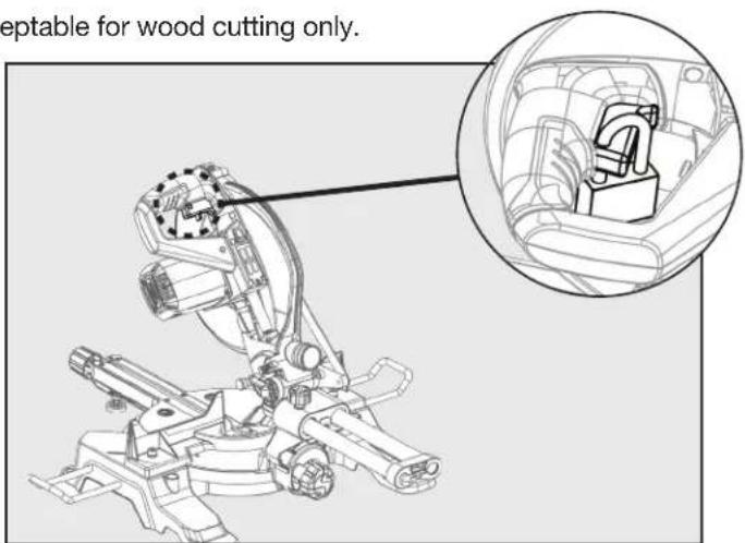

FIGURE 17
OPERATION
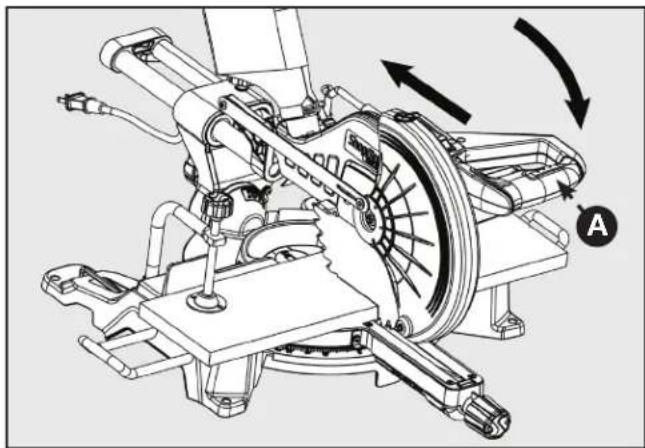
TO SLIDE CUT
WARNING:
Never make a cut by pulling the saw toward you. The blade can "climb" on
top of the workpiece and come toward you at an accelerated speed. Failure to heed this warning could result in serious personal injury.
See Figure 18.
With the saw off, pull the saw arm forward. Turn the saw on (wait for blade to reach full speed). push the blade down cutting into the workpiece, then back toward the rear of the saw to make a cut. Cuts must be made by pushing the saw blade away from you and toward the back of the saw stopping at the maximum rear position after each cut. While the saw is running, NEVER pull the saw blade toward you or toward the front of the saw. See warning above.
- Raise arm to its full height.
- Place the workpiece flat on the mitre table with one edge securely against the fence. If the board is warped, place the convex side against the fence. If the concave edge of a board is placed against the fence, the board could collapse on the blade at the end of the cut, jamming the blade.
- When cutting long pieces of lumber or molding, support the opposite end of the stock with a stand or with a work table level with the saw table.
- Align the cutting line on the workpiece with the blade or laser line.
- Loosen the slide lock knob.
- Hold the stock firmly with one hand, against the fence. Use the work clamp to secure the workpiece whenever possible.
- With the saw off, perform a dry run of the cut to make sure that no problems will occur when the actual cut is made.
- With the saw off, grasp the saw handle firmly then pull the saw forward until the center of the saw blade is over the front edge of the workpiece or until the saw is fully extended.
- Only use the saw handle (A) to place your hands. DO NOT place your hands on the motor housing.
- Squeeze the switch trigger. Allow the blade to reach maximum speed.
- Slowly lower the blade through the front edge of the workpiece.
- While holding the workpiece push the saw handle away from you and toward the back of the saw.
- Release the switch and allow the saw blade to stop rotating before raising the blade out of workpiece. After blade stops, remove the workpiece from mitre table.
NOTE: A cross cut is made by cutting across the grain of the workpiece. A straight cross cut is made with the mitre
natural_image
Technical line drawing of a mechanical assembly with rotating components and directional arrows (no text or symbols)FIGURE 18
table set at the 0^ position. Mitre cross cuts are made with the mitre table set at some angle other than 0^
BEVEL CUTS
A bevel cut is made across the grain with the blade angled to the workpiece. A straight bevel means the mitre scale indicator is set at 0^ and the bevel scale indicator is set at an angle other than 0^ .
COMPOUND MITRE CUTS
A compound mitre cut is made using a mitre angle and a bevel angle at the same time. Adjustments of mitre and bevel settings are interdependent. Each time you adjust the mitre setting change the effect of the bevel setting. Also, each time you adjust the bevel setting you change the effect of the mitre setting.
OPERATION
TIPS FOR CUTTING AND SUPPORTING WORKPIECES
TIPS FOR CUTTING CROWN MOLDING
- The two edges of the molding that contact the ceiling and the wall are at angles that, when added together, equal exactly 90°. Most crown molding has a top rear angle (the section that fits flat against the ceiling) of 52° and a bottom rear angle (the section that fits flat against the wall) of 38°.
- To accurately cut crown molding for a 90° inside or outside corner, lay the molding with its broad back surface flat on the mitre table and against the fence.
- The angles for crown moldings must be very precise. The bevel and mitre angles are interdependent; changing one angle changes the other angle as well.
- Since it is very easy for the work piece to shift, all settings should first be tested on scrap molding. Also most walls do not have angles of exactly 90°; therefore, you will need to fine-tune your settings.
- When cutting crown molding the bevel angle should be set at 33.85^ .
- The mitre angle should be set at 31.62° either right or left, depending on the desired cut for the application. See the chart below for correct angle settings and correct positioning of crown molding on the work table.
| Bevel Angle Setting Type of Cut Steps | ||
| 33.85° Left side, inside corner | 1. Top edge of molding against fence2. Mitre table set right 31.62°3. Save left end of cut | |
| 33.85° | Right side, inside corner | 1. Bottom edge of molding against fence2. Mitre table set left 31.62°3. Save left end of cut |
| 33.85° | Left side, outside corner | 1. Bottom edge of molding against fence2. Mitre table set left 31.62°3. Save right end of cut |
| 33.85° | Right side, outside corner | 1. Top edge of molding against fence2. Mitre table set right 31.62°3. Save right end of cut |
OPERATION
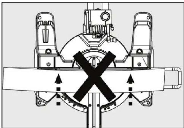
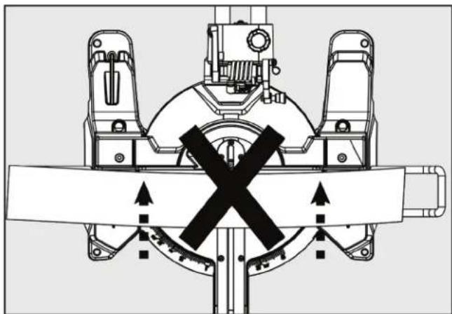
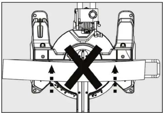
CUTTING WARPED MATERIAL
When attempting to cut warped material, the CONVEX face should be against the fence as shown in Figure 19. Never position a piece of warped material with the CONCAVE face or edge against the fence, as shown in Figure 20. It will pinch the blade near the completion of the cut.
⚠ WARNING: To avoid a kickback and to avoid serious personal injury, never position the concave edge of bowed or warped material against the fence.
natural_image
Technical line drawing of a mechanical assembly with no visible text or symbolsFIGURE 19
natural_image
Technical diagram of a mechanical device with cross-shaped component and directional arrows (no text or symbols)FIGURE 20
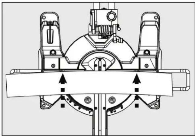
CLAMPING WIDE WORKPIECES
When cutting wide work pieces, such as 2 in. X 12 in., clamp the workpiece to the work table using a work clamp as shown in Figure 21.
⚠ WARNING: Keep clamps away from the path of the blade and blade guard assembly.
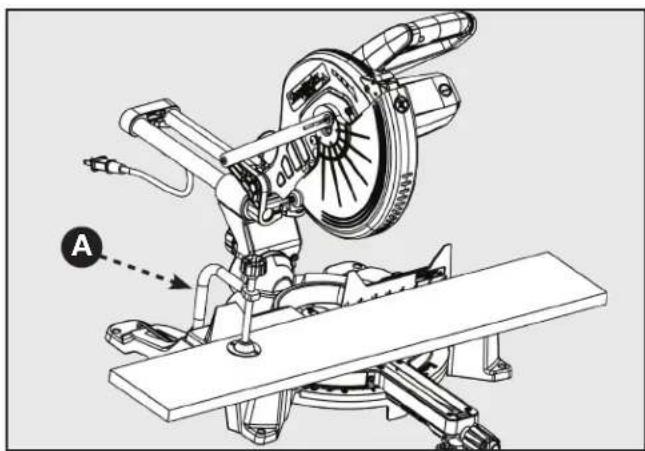
FIGURE 21
OPERATION
SUPPORTING LONG WORKPIECES
In most cases the included table extensions (workpiece supports) will be sufficient to support longer workpieces. If these are not long enough, the workpiece should be supported further out from the saw. Additional support (A) may be used to make the workpiece lay flat on the saw table. Use the included work clamp or a C-clamp (B) to secure the workpiece to the mitre saw table. See Figure 22.
WARNING:
Keep clamps away from the path of the blade and blade guard assembly.
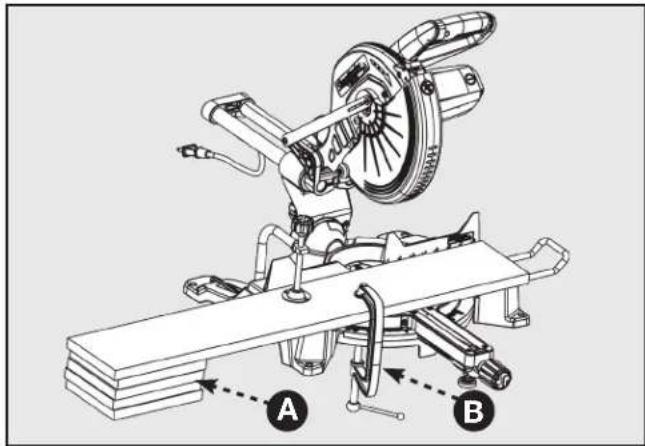
FIGURE 22
ADJUSTMENTS
WARNING:
Before performing any adjustment, make sure the tool is unplugged from the power supply. Failure to heed this warning could result in serious personal injury.
Your compound mitre saw has been properly adjusted at the factory. Due to shipping or normal use, it may be necessary to re-adjust some of the settings. Check the following adjustments periodically to assure proper accuracy and safe operation.
CAUTION:
Check for interference between the blade and the throat plate, before plugging the saw into the power source.
ARM PIVOT
The arm of the saw should raise and lower completely and freely. In the lowered position and with the lock pin removed, the arm should rise to the up position by itself. If the saw arm does not raise by itself or if there is play in the pivot joints, it will need to be professionally repaired at an AUTHORIZED SHOPMASTER SERVICE CENTER. Please call Company's Customer Care Center at 800-223-7278.
POSITIVE STOP SCREW
The position of the positive stop adjustment screw was set at the factory and normally will not require readjustment. If the blade is not square to the table, the positive stop adjustment screw must be re-adjusted.
To adjust refer to Figure 23.
- Unplug the saw
- Using the Phillips end of the blade wrench, loosen the positive stop adjustment screw (C) by turning it counterclockwise.
- Loosen the bevel lock knob (D) by turning it counterclockwise.
- Square the blade to the mitre table as described in the section entitled, ALIGN THE BLADE TO THE TABLE, found on page 12.
- Re-tighten bevel lock knob. Recheck blade-to-table alignment.
- The saw has two scale indicators, one on the bevel scale and one on the mitre scale. After squaring adjustments have been made, it may be necessary to loosen the indicator screws and reset them to zero.
NOTE: Use this procedure to check that the blade is square to the table at 0^ and 45^ angles.
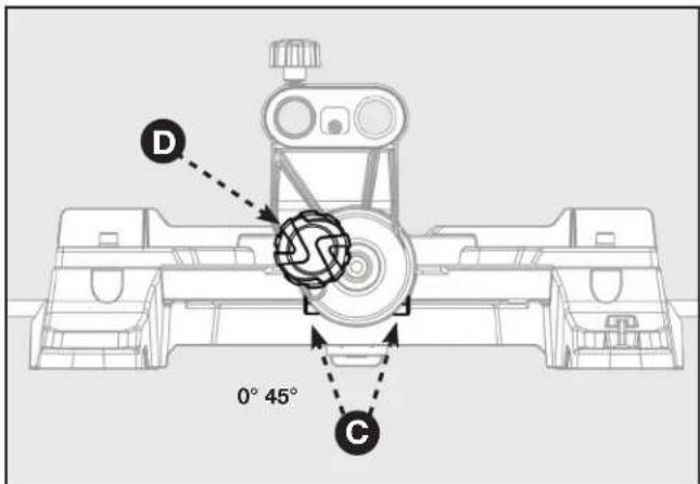
FIGURE 23
ADJUSTMENTS
BEVEL PIVOT
With the bevel lock knob loosened, the control arm of the saw should tilt easily from 0° and 45°. If it does not or if there is play in the pivot, the saw must be repaired by an AUTHORIZED SHOPMASTER SERVICE CENTER.
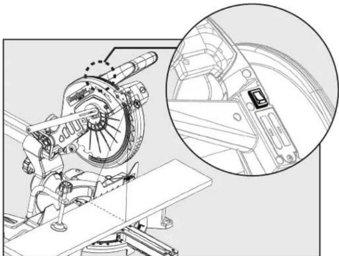
LASER ADJUSTMENTS
This saw is equipped with an adjustable laser which projects a red line onto the work piece surface, see Figure 24. Refer to the "Using Your Laser Guide" section on page 13 for more information on how to operate laser. This section will instruct you how to adjust the laser alignment for more accurate cuts.
DANGER:
Laser radiation. Avoid direct eye contact with light source.
WARNING:
- Avoid direct eye exposure to laser beam or reflection. Intense or prolonged exposure to laser radiation could permanently damage your eyes. Do not project or reflect the laser into anyone's eyes, including your own.
- Caution -- use of controls or adjustments or performance of procedures other than those specified herein may results in hazardous radiation exposure.
- Use or modification of the laser guide for anything other than its designed purpose may result in hazardous radiation exposure.
natural_image
Technical line drawing of a mechanical assembly with an inset close-up of the component (no text or symbols visible)FIGURE 24
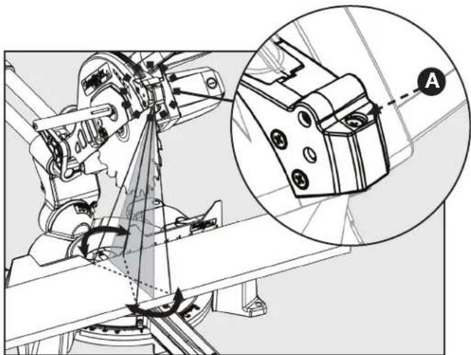
LASER PARALLEL ADJUSTMENT
If you notice the laser line is not perfectly parallel with the saw blade refer to Figure 25 and follow these instructions: using a Phillips head screwdriver turn screw (A) until the laser line is parallel with the saw blade.
natural_image
Technical diagram of a robotic arm with mechanical components and a magnified inset showing a close-up view of a mechanical component (no text or symbols present)FIGURE 25
ADJUSTMENTS
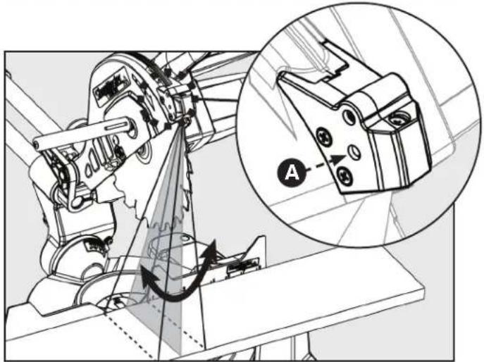
LASER VERTICAL ANGLE ADJUSTMENT
If you notice the laser line does not remain parallel to the blade as the saw head is lowered to make a cut refer to Figure 26 and follow these instructions: using a Phillips head screwdriver turn the screw (A) to adjust the vertical angle of the laser.
natural_image
Mechanical assembly diagram showing gear and motor components with a magnified inset highlighting a specific component (no text or symbols present)FIGURE 26
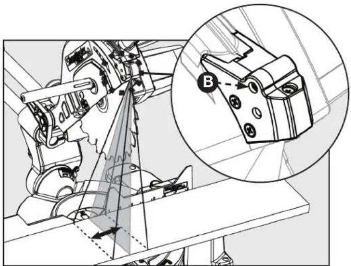
LASER OFFSET ADJUSTMENT
If you notice the laser line is offset from the actual cut line refer to Figure 27 and follow these instructions: using a Phillips head screwdriver turn the screw (B) to adjust the offset.
natural_image
Technical diagram of a mechanical assembly with an inset showing a close-up view of a component labeled B (no text or symbols present)FIGURE 27
DEPTH STOP ADJUSTMENT
This mitre saw is equipped with an adjustable depth stop for making through cuts and non-through cuts.
Refer to Figure 28 and follow these instructions in order to set the depth stop at a specific cut depth: use a Phillips head screwdriver to loosen screw (E) and then rotate the stop bracket (D) counterclockwise into the down position. Make sure to re-tighten screw (E). The cut depth can now be adjusted by turning the depth adjustment screw (C).
Refer to figure 28 and follow these instructions in order to make a through cut: use a Phillips head screwdriver to loosen screw (E) and then rotate the stop bracket (D) clockwise into the up position. Make sure to re-tighten screw (E).
▲DANGER: Always check to make sure screw (E) is tightened before making a cut. Failure to do so may result in injury.
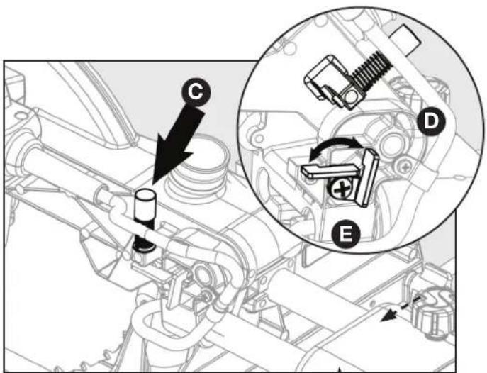
FIGURE 28
MAINTENANCE
⚠ WARNING: To reduce the risk of injury, turn unit off and disconnect it from power source
before cleaning or servicing, before installing and removing accessories, before adjusting when making repairs. An accidental start-up can cause injury.
KEEP MACHINE CLEAN
Periodically blow out all air passages with dry compressed air. All plastic parts should be cleaned with a soft damp cloth. NEVER use solvents to clean plastic parts. They could possibly dissolve or otherwise damage the material. Wear certified safety equipment for eye, hearing and respiratory protection while using compressed air.
Empty dust bag frequently.
⚠ WARNING: When servicing, use only identical replacement parts. Use of any other
parts may create a hazard or cause product damage.
GENERAL MAINTENANCE
Avoid using solvents when cleaning plastic parts. Most plastics are susceptible to damage from various types of commercial solvents and may be damaged by their use.
BRUSH REPLACEMENT
The motor on this saw features externally accessible brush assemblies that should be periodically checked for wear. If the brushes need to be replaced, refer to Figure 29 and proceed as follows:
- Unplug the saw.
⚠ WARNING: Failure to unplug the saw could result in accidental starting causing serious
personal injury.
- Using a screwdriver, carefully remove the brush cap (A).
NOTE: Remove the cap slowly. The brush assembly is spring-loaded and will pop out once the cap is removed.
-
Remove brush assembly (B).
-
Inspect both brushes. If either has less than 1/4 in. length of carbon remaining, both brushes should be replaced.
NOTE: Do not replace one side without replacing the other.
-
Insert both brushes into the brush tube (C), making sure the curvature of the brushes matches curvature of motor. Brush assembly should move freely within the tube.
-
Carefully replace the brush cap, ensuring that it is not cross-threaded.
-
Tighten brush cap securely. Do not over-tighten.
Use clean cloths to remove dirt, dust, oil, grease, etc.
⚠ WARNING: Do not at any time let brake fluids, gasoline, petroleum-based products, penetrating oils, etc., come in contact with plastic parts. Chemicals can damage, weaken or destroy plastic which may result in serious personal injury.
Electric tools used on fiberglass material, wallboard, spackling compounds, or plaster are subject to accelerated wear and possible premature failure because the fiberglass chips and grindings are highly abrasive to bearings, brushes, commutator, etc. Consequently, we do not recommend using this tool for extended work on these types of materials. However, if you do work with any of these materials, it is extremely important to clean the tool using compressed air.
LUBRICATION
All of the bearings in this tool are lubricated with a sufficient amount of high-grade lubricant for the life of the unit under normal operating conditions. Therefore, no further lubrication is required.
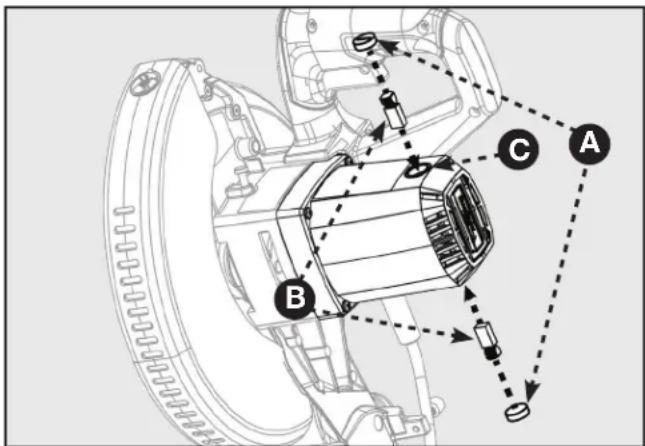
FIGURE 29
TROUBLESHOOTING
FAILURE TO START
If your machine fails to start, check to make sure the prongs on the cord plug are making good contact in the receptacle. Also, check for blown fuses or open circuit breakers in your power supply line. If the saw still does not start, call Company's Customer Care Center at 1-800-223-7278.
ACCESSORIES
For accessories please visit our Web Site for an on-line catalog or for the name or your nearest supplier.
WARNING:
Since accessories other than those offered by DELTA ^® have not been tested with this product, use of such accessories could be hazardous. For safest operation, only DELTA ^® /SHOPMASTER recommended accessories should be used with this product.
PARTS, SERVICE OR WARRANTY ASSISTANCE
All SHOPMASTER Machines and accessories are manufactured to high quality standards and are serviced by a network of DELTA® Authorized Service Centers. To obtain additional information regarding your product or to obtain parts, service, warranty assistance, or the location of the nearest service center, please call 1-800-223-7278.
Three Year Limited Warranty
- WHAT IS COVERED. Delta Power Equipment Corporation ("Company") will, at its option, repair or replace this SHOPMASTER product, if purchased at retail in the United States or Canada and the product, with normal use, has proven to be defective in workmanship or material, subject to the conditions stated in this Limited Warranty. This Limited Warranty covers only materials and labor. All transportation costs are Customer's responsibility.
- WARRANTY PERIOD. All warranty claims must be submitted within three years from the date of retail purchase. For all service parts and factory refurbished SHOPMASTER products, the warranty period is 180 days.
- HOW TO OBTAIN SERVICE. To obtain warranty service, you must return the defective product, at your expense, to a service center authorized by Company to perform warranty service (a "Company Authorized Service Center") within the applicable warranty period, together with acceptable proof of purchase, such as your original receipt bearing the date of purchase, or product registration number. Company reserves the right to restrict warranty claim service to the country where the purchase was made and/or to charge for the cost to export service parts or provide warranty service in a different country. For this purpose, on-line purchases are deemed made in the United States. For the location of your nearest Company Authorized Service Center, call Company's Customer Care Center at (800) 223-7278.
- EXCLUSIONS.
- Company does not offer any warranty on products purchased in used or damaged condition.
• Company does not warrant any products purchased outside the United States or Canada - Company will not be responsible for any damage that has resulted from normal wear, misuse, abuse or any repair or alteration made by anyone other than a Company Authorized Service Center or a designated representative of Company's Customer Care Center.
- All IMPLIED WARRANTIES are expressly limited to the warranty period identified above.
- Company will not be liable for INCIDENTAL OR CONSEQUENTIAL damages.
- This limited warranty is Company's sole warranty and sets forth the customer's exclusive remedy with respect to defective products; all other warranties, express or implied, whether of merchantability, fitness for purpose, or otherwise, are expressly disclaimed by Company, except as expressly stated in this warranty statement.
Some states do not allow the exclusion or limitation of incidental or consequential damages, or the limitation of implied warranties, so the above limitations or exclusions may not apply to you. This warranty gives you specific legal rights and you may have other rights which vary in certain states or provinces. For further details of warranty coverage and warranty repair information, call (800) 223-7278. To register your products on-line, we encourage you to visit our website and register for a FREE DELTA ^® Member Account at http://www.deltamachinery.com/register.
LATIN AMERICA: This warranty does not apply to products sold in Latin America. For products sold in Latin America, call the local company or see website for warranty information.
REPLACEMENT PARTS
The only user replaceable parts on this tool are:
1) Saw Blade
2) Motor Brushes
All other parts not listed above must be replaced by an authorized DELTA® agent. Use only identical replacement parts. For a parts list or to order parts, visit our website at www.DeltaMachinery.com/service. You can also order parts from your nearest Authorized Warranty Service Center or by calling Technical Service Manager at 1-800-223-7278 to receive personalized support from one of our highly-trained representatives.
FREE WARNING LABEL REPLACEMENT
If your warning labels become illegible or are missing, call 1-800-223-7278 for a free replacement.
SERVICE AND REPAIRS
All quality tools will eventually require servicing and/or replacement of parts. For information about Delta Power Equipment Corporation, its factory-owned branches, or to locate an Authorized Warranty Service Center, visit our website at www.DeltaMachinery.com/service or call Customer Care at 1-800-223-7278. All repairs made by our service centers are fully guaranteed against defective material and workmanship. We cannot guarantee repairs made or attempted by others. By calling this number you can also find answers to most frequently asked questions 24 hours/day. You can also write to us for information at Delta Power Equipment Corporation, 2651 New Cut Road, Spartanburg, SC 29303 - Attention: Technical Service Manager. Be sure to indicate all of the information shown on the nameplate of your saw (model number, type, serial number, date code, etc.).
ShopMaster
DELTA®
10-INCH SLIDING COMPOUND MITRE SAW
SCIE À ONGLET COMBINE
254 MM
SIERRA INGLETADORA
COMPUESTA DE 10
PULGADAS
Français (23)
Español (46)
www.DeltaMachinery.com
Instruction Manual
REMPLACEMENT DES BROSSES....43
DÉPANNAGE....44
ACCESSOIRES 44
ASSISTANCE POUR PIÈCES, SERVICES OU GARANTIE.... 44
CONSIGNES IMPORTANTES DE SÉCURITÉ
AVERTISSEMENT : LISEZ ATTENTIVEMENT LES AVERTISSEMENTS ET LES INSTRUCTIONS SUR VOTRE PRODUIT DANS CE GUIDE ET SUIVEZ-LES TOUS. CONSERVEZ CE GUIDE. ASSUREZ-VOUS QUE TOUS LES UTILISATEURS SONT FAMILIERS AVEC LES AVERTISSEMENTS ET INSTRUCTIONS
SPÉCIFICATIONS DU PRODUIT
FIGURE 1
APPRENEZ À CONNAÎTRE VOTRE SCIE À ONGLETS COMBINÉE
natural_image
Five technical illustrations of mechanical components labeled A through F, including a motor, battery, pipe fitting, and cylindrical tubes (no text or symbols beyond labels)DESCRIPTION DU CONTENU (QTÉ)
BASE WITH CARRY HANDLES
Use the carry handles which are designed into the base for safe and easy transportation of the saw. Shown in Fig. 4.
MONTAGE DE LA SCIE SUR UNE SURFACE STABLE
AVERTISSEMENT :
FIGURE 3

natural_image
Technical line drawing of a mechanical gun or weapon system with labeled component B (no text or symbols beyond label)FIGURE 4
natural_image
Technical line drawing of a mechanical assembly with no visible text or symbolsFIGURE 5
MONTAGE
AVERTISSEMENT :
FIGURE 7
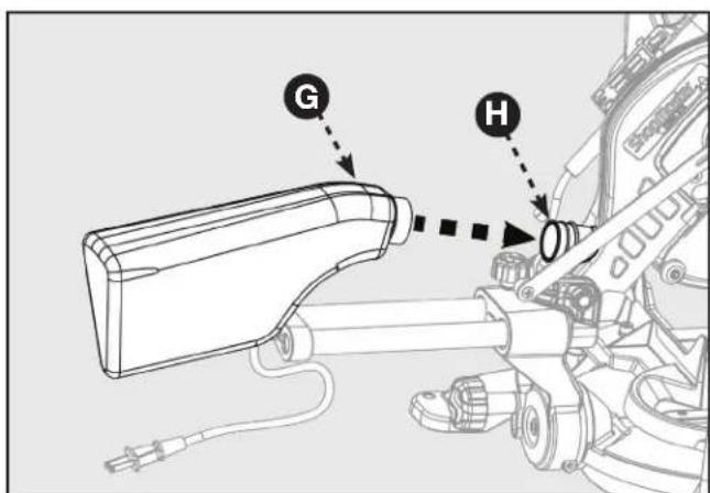
FIGURE 8
MONTAGE
INSTALLER LES PILES POUR LASER
INSTALLER/REEMPLACER LA LAME
FIGURE 11
FIGURE 12

FIGURE 13
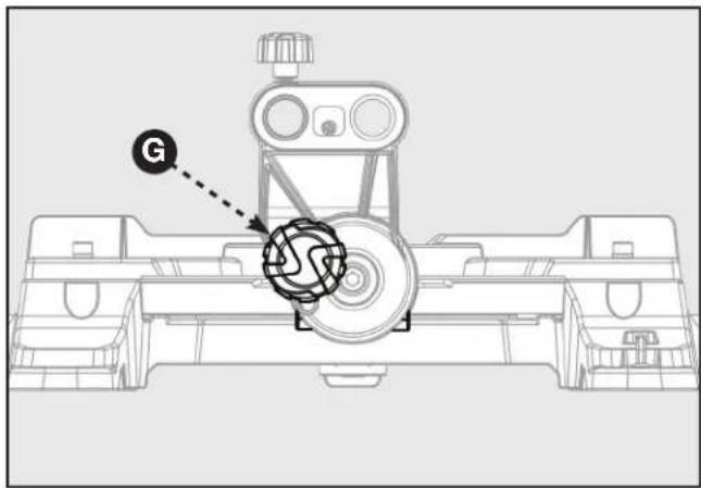
FIGURE 14
PRÉPARER VOTRE SCIE POUR L'UTILISATION
UTILISATION DU GUIDE LASER
FIGURE 15
UTILISATION
AVERTISSEMENT :
natural_image
Technical line drawing of a mechanical assembly with an inset showing a close-up of a component (no text or symbols present)FIGURE16
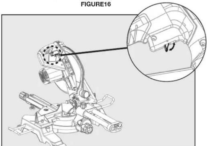
FIGURE 17
UTILISATION
FAIRE UNE COUPE EN GLISSIÈRE

AVERTISSEMENT :
natural_image
Technical line drawing of a mechanical assembly with rotating components and directional arrows (no text or symbols)FIGURE 18
COUPES EN BISEAU
natural_image
Technical line drawing of a mechanical assembly with no visible text or symbolsFIGURE 19
natural_image
Technical diagram of a mechanical device with no visible text, numbers, or symbolsFIGURE 20
SERRAGE DES GRANDES PIÈCES
FIGURE 21
UTILISATION
SOUTIEN DES LONGUES PIÈCES
FIGURE 22
RÉGLAGES
AVERTISSEMENT :
natural_image
Technical line drawing of a mechanical assembly with an inset close-up showing a component detail (no text or symbols)FIGURE 24
RÉGLAGE DU PARALLÈLE DU LASER
natural_image
Technical diagram of a mechanical assembly with an inset showing a close-up of a component labeled 'A' (no text or symbols present)FIGURE 25
RÉGLAGES
RÉGLAGE DE L'ANGLE VERTICAL DU LASER
natural_image
Technical diagram of a mechanical assembly with an inset showing a close-up of a component labeled 'A' (no text or symbols present)FIGURE 26
RÉGLAGE DU DÉPORT DU LASER
natural_image
Mechanical assembly diagram showing gear and motor components with a magnified inset highlighting a specific component (no text or labels present)FIGURE 27
AJUSTEMENT DE LA PROFONDEUR
TENIR LA MACHINE PROPRE
REPLACEMENT DES BROSSES
FIGURE 29
DÉPANNAGE
DÉMARRAGE IMPOSSIBLE
ASSISTANCE POUR PIÈCES, SERVICE OU GARANTIE
ASSISTANCE POUR PIÈCES, SERVICE OU GARANTIE
PIÈCES DE REMPLACEMENT
FIGURA 1
natural_image
Illustration of various mechanical components and parts, including a pump, battery, pipe fittings, and cylindrical tanks (no text or labels present)FIGURA 2
FIGURA 3
natural_image
Technical line drawing of a mechanical gun or weapon system with labeled component B (no text or symbols beyond label)FIGURA 4
natural_image
Technical line drawing of a mechanical component with no visible text or symbolsFIGURA 5
ENSAMBLE
ADVERTENCIA:
FIGURA 7

FIGURA 8
ENSAMBLE
FIGURA 11
FIGURA 12
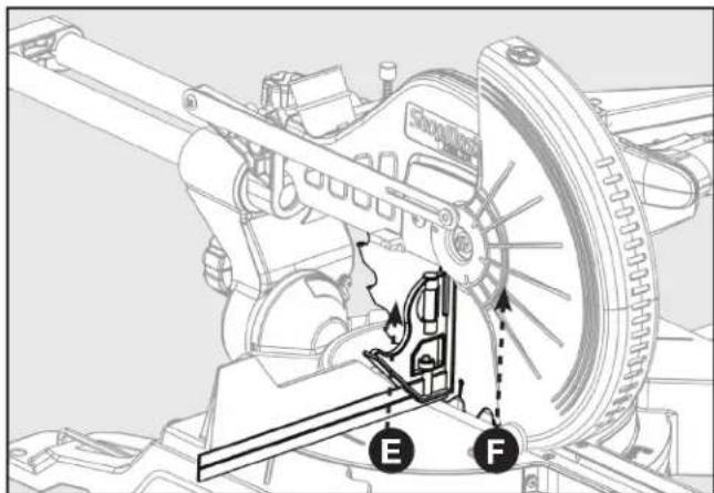
FIGURA13
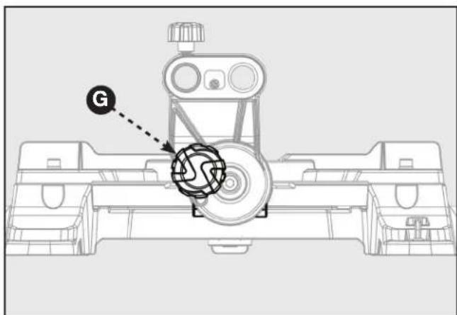
FIGURA 14
FIGURA 15
FUNCIONAMIENTO
ADVERTENCIA:
natural_image
Technical line drawing of a mechanical assembly with an inset showing a close-up of a component (no text or symbols present)FIGURA 16
natural_image
Technical line drawing of a mechanical assembly with an inset showing a close-up of a component detail (no text or symbols present)FIGURA 17
FUNCIONAMIENTO
CORTE DESLIZANTE
natural_image
Technical line drawing of a mechanical assembly with rotating components and directional arrows (no text or symbols)FIGURA 18
natural_image
Technical line drawing of a mechanical assembly with no visible text or symbolsFIGURA 19
natural_image
Technical diagram of a mechanical device with cross-shaped component and directional arrows (no text or symbols)FIGURA 20
FIGURA 21
FUNCIONAMIENTO
APOYO DE PIEZAS DE TRABAJO LARGAS
FIGURA 22
AJUSTES
ADVERTENCIA:
natural_image
Technical line drawing of a mechanical assembly with a magnified inset showing internal components (no text or symbols)FIGURA 24
AJUSTE PARA LOGRAR UN LÁSER PARALELO
natural_image
Technical diagram of a mechanical assembly with an inset close-up showing a component labeled 'A' (no text or symbols present)FIGURA 25
AJUSTES
AJUSTE DEL ÁNGULO VERTICAL DEL LÁSER
natural_image
Technical diagram of a mechanical assembly with an inset showing a close-up of a component labeled 'A' (no text or symbols present)FIGURA 26
natural_image
Mechanical assembly diagram showing gear and bracket components with an inset magnified view (no text or symbols)FIGURA 27
AJUSTE DE DEPTH STOP
MANTENIMIENTO
ADVERTENCIA:
FIGURA 29
Copyright © 2018 Delta Power Equipment Corporation
DPEC005213
Revision date: 05/10/2019
Rv.12


- IMPORTANT SAFETY INSTRUCTIONS
- SAFETY LOGOS
- GENERAL POWER TOOL SAFETY WARNINGS
- 1) Work area safety
- 2) Electrical safety
- 3) Personal safety
- 4) Power tool use and care
- GENERAL POWER TOOL SAFETY RULES
- 5) Service
- SAFETY INSTRUCTIONS FOR MITRE SAWS
- PROPOSITION 65 WARNING:
- WARNING:
- SAVE THESE INSTRUCTIONS.
- POWER CONNECTIONS
- DANGER:
- DOUBLE INSULATION
- ELECTRICAL CONNECTION
- POLARIZED PLUGS
- EXTENSION CORDS
- FEATURES
- PRODUCT SPECIFICATIONS
- KNOW YOUR COMPOUND MITRE SAW
- UNPACKING AND ASSEMBLY
- CONTENT DESCRIPTION (QTY)
- MOUNTING AND TRANSPORTATION
- PREPARATIONS FOR TRANSPORTATION
- BASE WITH CARRY HANDLES
- MOUNTING THE SAW TO A STABLE SURFACE
- ASSEMBLY
- SUPPORT EXTENSIONS
- ATTACHING WORK CLAMP
- INSTALL DUST COLLECTION BAG
- INSTALL BATTERIES FOR LASER
- PREPARING YOUR SAW FOR USE
- INSTALL/REPLACE THE BLADE
- ALIGN THE BLADE TO THE TABLE
- Refer to Figure 12.
- USING THE LASER GUIDE
- TO REMOVE YOUR MARK:
- TO CUT ON YOUR MARK:
- TO CUT WITHOUT REMOVING YOUR MARK:
- FREE WARNING LABEL REPLACEMENT
- CAUTION:
- OPERATION
- POWER SWITCH LOCK-OUT
- POWER SAFETY TOGGLE
- TO SLIDE CUT
- BEVEL CUTS
- COMPOUND MITRE CUTS
- TIPS FOR CUTTING AND SUPPORTING WORKPIECES
- TIPS FOR CUTTING CROWN MOLDING
- CUTTING WARPED MATERIAL
- CLAMPING WIDE WORKPIECES
- SUPPORTING LONG WORKPIECES
- ADJUSTMENTS
- ARM PIVOT
- POSITIVE STOP SCREW
- BEVEL PIVOT
- LASER ADJUSTMENTS
- LASER PARALLEL ADJUSTMENT
- LASER VERTICAL ANGLE ADJUSTMENT
- LASER OFFSET ADJUSTMENT
- DEPTH STOP ADJUSTMENT
- MAINTENANCE
- KEEP MACHINE CLEAN
- GENERAL MAINTENANCE
- BRUSH REPLACEMENT
- LUBRICATION
- TROUBLESHOOTING
- FAILURE TO START
- ACCESSORIES
- PARTS, SERVICE OR WARRANTY ASSISTANCE
- Three Year Limited Warranty
- REPLACEMENT PARTS
- SERVICE AND REPAIRS
- ShopMaster
- DELTA®
- 10-INCH SLIDING COMPOUND MITRE SAW
- SCIE À ONGLET COMBINE
- SIERRA INGLETADORA
- COMPUESTA DE 10
- PULGADAS
- CONSIGNES IMPORTANTES DE SÉCURITÉ
- SPÉCIFICATIONS DU PRODUIT
- APPRENEZ À CONNAÎTRE VOTRE SCIE À ONGLETS COMBINÉE
- DESCRIPTION DU CONTENU (QTÉ)
- MONTAGE DE LA SCIE SUR UNE SURFACE STABLE
- AVERTISSEMENT :
- MONTAGE
- INSTALLER LES PILES POUR LASER
- INSTALLER/REEMPLACER LA LAME
- PRÉPARER VOTRE SCIE POUR L'UTILISATION
- UTILISATION DU GUIDE LASER
- UTILISATION
- FAIRE UNE COUPE EN GLISSIÈRE
- COUPES EN BISEAU
- SERRAGE DES GRANDES PIÈCES
- SOUTIEN DES LONGUES PIÈCES
- RÉGLAGES
- RÉGLAGE DU PARALLÈLE DU LASER
- RÉGLAGE DE L'ANGLE VERTICAL DU LASER
- RÉGLAGE DU DÉPORT DU LASER
- AJUSTEMENT DE LA PROFONDEUR
- TENIR LA MACHINE PROPRE
- REPLACEMENT DES BROSSES
- DÉPANNAGE
- DÉMARRAGE IMPOSSIBLE
- ASSISTANCE POUR PIÈCES, SERVICE OU GARANTIE
- PIÈCES DE REMPLACEMENT
- ENSAMBLE
- ADVERTENCIA:
- FUNCIONAMIENTO
- CORTE DESLIZANTE
- APOYO DE PIEZAS DE TRABAJO LARGAS
- AJUSTES
- AJUSTE PARA LOGRAR UN LÁSER PARALELO
- AJUSTE DEL ÁNGULO VERTICAL DEL LÁSER
- AJUSTE DE DEPTH STOP
- MANTENIMIENTO
Brand : DELTA
Model : ShopMaster S26‑263LS
Category : Saw