
36-T30 - Saw DELTA - Free user manual and instructions
Find the device manual for free 36-T30 DELTA in PDF.

| Product Type | Guide system (fence) for table saw |
| Brand | Delta |
| Model | 36-T30 |
| Usage | Guiding workpieces during table saw cuts |
| Main Components | Front guide rail, rear guide rail, guide tube, fence, mounting hardware |
| Materials | Metal (steel or aluminum rails), plastic for some parts |
| Rail Dimensions (approx.) | 30-inch (76 cm) long rails (model 36-T30) |
| Weight (approx.) | Approximately 10 kg (depending on configuration) |
| Power | None (mechanical accessory) |
| Main Functions | Parallel guidance, alignment with table slots, square adjustment |
| Adjustments | Parallelism, perpendicularity, clamping lever tension, pointer position |
| Maintenance | Regular cleaning, waxing sliding surfaces, lubricating lock cams |
| Safety | Read manual, use protective equipment, unplug before adjustments |
| Spare Parts and Repairability | Parts available through Delta authorized service center, service number: 1-800-223-7278 |
| Warranty | 2-year limited warranty (materials and workmanship) |
| General Information | Accessory compatible with many Delta and other brand saw stands |
Frequently Asked Questions - 36-T30 DELTA
User questions about 36-T30 DELTA
0 question about this device. Answer the ones you know or ask your own.
Ask a new question about this device
Download the instructions for your Saw in PDF format for free! Find your manual 36-T30 - DELTA and take your electronic device back in hand. On this page are published all the documents necessary for the use of your device. 36-T30 by DELTA.
USER MANUAL 36-T30 DELTA
natural_image
Technical line drawing of a mechanical assembly with two parallel plates and a central shaft (no text or symbols)Français (14)
Español (26)
www.DeltaMachinery.com
Instruction Manual
To reduce risk of serious injury, thoroughly read and comply with all warnings and instructions in this manual and on product. KEEP THIS MANUAL NEAR YOUR SAW FOR EASY REFERENCE AND TO INSTRUCT OTHERS.
TABLE OF CONTENTS
FUNCTIONAL DESCRIPTION ......2
IMPORTANT SAFETY INSTRUCTIONS ....3
SAFETY GUIDELINES - DEFINITIONS ....3
GENERAL SAFETY RULES 4
CARTON CONTENTS 5
ASSEMBLY 6
OPERATION AND ADJUSTMENT....9
TROUBLESHOOTING ....12
MAINTENANCE 12
TROUBLESHOOTING 12
ACCESSORIES .... 13
WARRANTY 13
PARTS, SERVICES AND WARRANTY ASSISTANCE ..... 1 3
REPLACEMENT PARTS 13
FRENCH....14
SPANISH 26
FUNCTIONAL DESCRIPTION
The DELTA ^® 36-T30 r and the DELTA ^® 36-T50 r Fence Systems include the Fence Assembly, Front Rail, Rear Rail and Front Guide Tube along with the Mounting Hardware for assembling the Fence System to most DELTA ^® Table Saws and to some non-DELTA ^® Table Saws.
In addition, the DELTA ^® 36-T50 _tt Fence System also includes an Accessory Leg Kit, to be used with a Wooden Extension Table. The Wooden Extension Table is purchased separately or can be constructed by following the instructions in this manual.
NOTICE: The illustrations contained in this manual show the 36-T30 _1 fence system as it installs on the DELTA ^® 36-729 table saw. These figures are intended to illustrate technique only. The specific configurations and hardware needed to attach this fence to your particular saw may vary.
NOTICE: The manual cover illustrates the current production model. All other illustrations contained in the manual are representative only and may not be exact depictions of the actual labeling or accessories included. They are intended for illustrative purposes only.
PROPOSITION 65 WARNING:
⚠ WARNING: Some dust created by power sanding, sawing, grinding, drilling, and other construction activities contains chemicals known to the state of California to cause cancer, birth defects or other reproductive harm. Some examples of these chemicals are:
- Lead from lead-based paints
- Crystalline silica from bricks and cement and other masonry products
- Arsenic and chromium from chemically-treated lumber
Your risk from these exposures varies, depending on how often you do this type of work. To reduce your exposure to these chemicals: work in a well-ventilated area and work with approved safety equipment, such as dust masks that are specifically designed to filter out microscopic particles.
SAVE THESE INSTRUCTIONS.
Refer to them often and use them to instruct others.
If tool is loaned to someone, also loan them these instructions.
IMPORTANT SAFETY INSTRUCTIONS
WARNING: CAREFULLY READ AND FOLLOW ALL WARNINGS AND INSTRUCTIONS ON YOUR PRODUCT AND IN THIS MANUAL. SAVE THIS MANUAL. MAKE SURE ALL USERS ARE FAMILIAR WITH IT'S WARNING
AND INSTRUCTIONS WHEN USING THE TOOL. Improper operation, maintenance or modification of tools or equipment could result in serious injury and/or property damage.
If you have any questions or concerns relative to the use of your tool or the contents of this manual, stop using the tool and contact DELTA® Power Equipment Corporation Customer Care at 1-800-223-7278.
SAFETY LOGOS
This manual contains information that is important for you to know and understand. This information relates to protecting YOUR SAFETY and PREVENTING EQUIPMENT PROBLEMS. To help you recognize this information, we use the symbols below. Please read the manual and pay attention to these sections:
DANGER:
WARNING:
CAUTION:
CAUTION:
Indicates an imminently hazardous situation which, if not avoided, will result in death or serious injury.
Indicates a potentially hazardous situation which, if not avoided, could result in death or serious injury.
Indicates a potentially hazardous situation which, if not avoided, may result in minor or moderate injury.
Used without the safety alert symbol indicates potentially hazardous situation which, if not avoided, may result in property damage.
Additional information regarding the safe and proper operation of this tool is available from the following sources:
• Power Tool Institute, 1300 Sumner Avenue, Cleveland, OH 44115-2851 or on-line at www.powertoolinstitute.com
• National Safety Council, 1121 Spring Lake Drive, Itasca, IL 60143-3201
- American National Standards Institute, 25 West 43rd Street, 4^th floor, New York, NY 10036 www.ansi.org - ANSI 01.1 Safety Requirements for Woodworking Machines
• U.S. Department of Labor regulations www.osha.gov
| Some of the following symbols may be used on this tool. Please study them and learn their meaning. Proper interpretation of these symbols will allow you to operate the tool better and safer. | |||
| SYMBOL NAME DESIGNATION/EXPLANATION | |||
| [BG8K] | Safety Alert | Indicates a potential personal injury hazard. | |
 | Read Operator's Manual | To reduce the risk of injury, user must read and understand operator's manual before using this product. | |
 | Eye Protection | Always wear eye protection with side shields marked to comply with ANSI Z87.1. | |
 | No Hands Symbol | Failure to keep your hands away from the blade will result in serious personal injury. | |
 | Wet Conditions Alert | Do not expose to rain or use in damp locations. | |
 | Pinch Warning | Always watch for movement paying extra attention to potential areas where pinching could occur. | |
| V | Volts | Voltage | |
| A | Amperes | Current | |
| Hz | Hertz | Frequency (cycles per second) | |
| min | Minutes | Time | |
| ~ | Alternating Current | Type of current | |
| n_0 | No Load Speed | Rotational speed, at no load | |
| .../min | Per Minute | Revolutions, strokes, surface speed, orbits, etc., per minute | |
| A.C | Alternating Current | Type of current | |
| Kg | Kilograms | Unit of weight | |
| RPM | Revolutions Per Minute | Speed of rotation of machine | |
| PH:1 Phase 1 | This is a 1 phase motor | ||
GENERAL POWER TOOL SAFETY WARNINGS
WARNING:
Read all safety warnings, instructions, illustrations and specifications provided with this power tool.
Failure to follow all instructions listed below may result in electric shock, fire and/or serious injury.
Save all warnings and instructions for future reference.
The term "power tool" in the warnings refers to your main-operated (corded) power tool or BATTERY-operated (cordless) power tool.
1. Work area safety
a. Keep work area clean and well lit. Cluttered or dark areas invite accidents.
b. Do not operate power tools in explosive atmospheres, such as in the presence of flammable liquids, gases or dust. Power tools create sparks which may ignite the dust or fumes.
c. Keep children and bystanders away while operating a power tool. Distractions can cause you to lose control.
2. Electrical safety
a. Power tool plugs must match the outlet. Never modify the plug in any way. Do not use any adapter with earthed (grounded) power tools. Unmodified plugs and matching outlets will reduce risk of electric shock.
b. Avoid body contact with earthed or grounded surfaces, such as pipes, radiators, ranges and refrigerators. There is an increased risk of electric shock if your body is earthed or grounded.
c. Do not expose power tools to rain or wet conditions. Water entering a power tool will increase the risk of electric shock.
d. Do not abuse the cord. Never use the cord for carrying, pulling or unplugging the power tool. Keep cord away from heat oil, sharp edges or moving parts. Damaged or entangled cords increase the risk of electric shock.
e. When operating a power tool outdoors, use an extension cord suitable for outdoor use. Use of a cord suitable for outdoor use reduces the risk of electric shock.
f. If operating a power tool in a damp location is unavoidable, use a ground fault circuit interrupter (GFCI) protected supply. Use of an GFCI reduces the risk of electric shock.

3. Personal safety
a. Stay alert, watch what you are doing and use common sense when operating a power tool. Do not use a power tool while you are tired or under the influence of drugs, alcohol or medication. A moment of inattention while operating power tools may result in serious personal injury.
b. Use personal protective equipment. Always wear eye protection. Protective equipment such as dust mask, non-skid safety shoes, hard hat, or hearing protection and dust protection used for appropriate conditions will reduce personal injuries. Gloves are recommended when changing blades.
c. Prevent unintentional starting. Ensure the switch is in the off-position before connection to power source, picking up, or carrying the tool. Carrying power tools with your finger on the switch or energising power tools that have the switch on invites accidents.
d. Remove any adjusting key or wrench before turning the power tool on. A wrench or a key left attached to a rotating part of the power tool may result in personal injury.
e. Do not overreach. Keep proper footing and balance at all times. This enables better control of the power tool in unexpected situations.
f. Dress properly. Do not wear loose clothing or jewelry. Keep your hair, clothing and gloves away from moving parts. Loose clothes, jewelry or long hair can be caught in moving parts.
g. If devices are provided for the connection of dust extraction and collection facilities, ensure these are connected and properly used. Use of dust collection can reduce dust-related hazards.
h. Do not let familiarity gained from frequent use of tools allow you to become complacent and ignore tool safety principles. A careless action can cause severe injury within a fraction of a second.
4. Power tool use and care
a. Do not force the power tool. Use the correct power tool for you application. The correct power tool will do the job better and safer at the rate for which it was designed.
b. Do not use the power tool if the switch does not turn it on and off. Any power tool that cannot be controlled with the switch is dangerous and must be repaired.
c. Disconnect the plug from the power source before making any adjustments, changing accessories, or storing power tools. Such preventive safety measures reduce the risk of starting the power tool accidentally.
d. Store idle power tools out of the reach of children and do not allow persons unfamiliar with the power tool or these instructions to operate the power tool. Power tools are dangerous in the hands of untrained users.
e. Maintain power tools and accessories. Check for misalignment or binding of moving parts, breakage of parts and any other condition that may affect the power tool's operation. If damaged, have the power tool repaired before use. Many accidents are caused by poorly maintained power tools.
f. Keep cutting tools sharp and clean. Properly maintained cutting tools with sharp cutting edges are less likely to bind and are easier to control.
g. Use the power tool, accessories and tools bits etc. in accordance with these instructions, taking into account the working conditions and the work to be performed. Use of the power tool for operations different from those intended could result in a hazardous situation.
h. Keep handles and grasping surfaces dry, clean and free from oil and grease. Slippery handles and grasping surfaces do not allow for safe handling and control of the tool in unexpected situations.
5. Service
a. Have your power tool serviced by a qualified repair person using only identical replacement parts. This will ensure that the safety of the power tool is maintained.
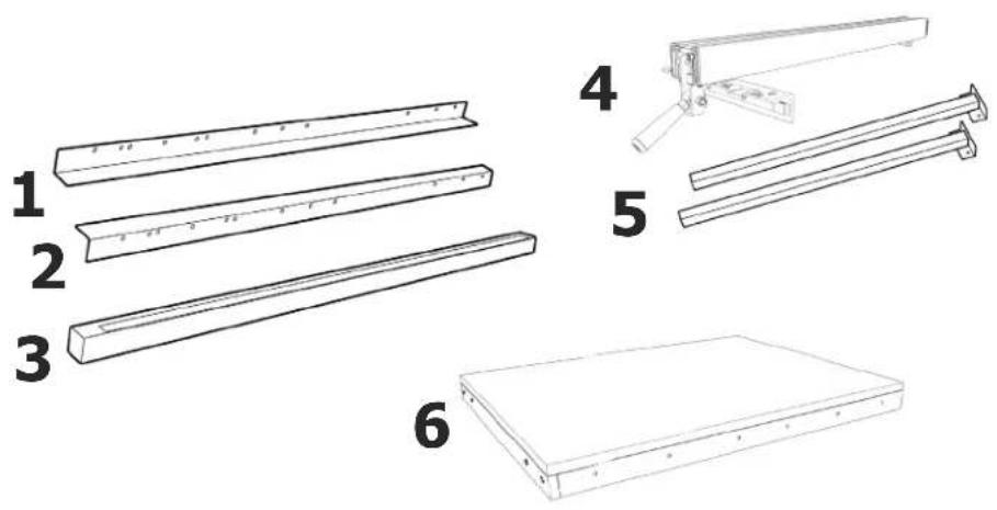
CARTON CONTENTS
CARTON CONTENTS
- Front Guide Rail (1)
- Rear Guide Rail (1)
- Guide Tube (1)
- Fence (1)
- Support Legs (36-T50 Only) (2)
- Extension Table (36-T50 _TA Only) (1)
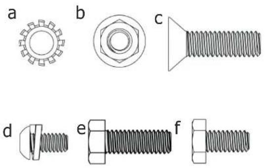
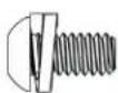
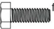
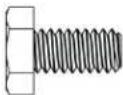
HARDWARE PACKAGE
(included with the 36-T30 _T3 )
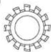
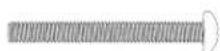
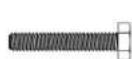
a. 5/16" External Tooth Lockwasher (14)
b. 5/16" Hex Flange Nut (17)
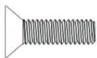
c. 5/16" Countersunk Screw (8)
d. 1/4" Pan Head Screw with Washer (4)
e. 5/16" Hex Socket Screw (17)
f. 1/4-20 x 1/2" Hex Cap Screw (2)
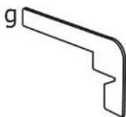
g. Rail Alignment Gauge (1)
HARDWARE PACKAGE
(included with the 36-T50 _13 )
a. 5/16" External Tooth Lock Washer (10)
b. 5/16" Hex Flange Nut (13)
c. 5/16" Countersunk Screw (6)
d. 1/4" Pan Head Screw with Washer (6)
e. 5/16" Hex Socket Screw (13)
f. 1/4-20 x 1/2" Hex Cap Screw (2)
g. Rail Alignment Gauge (1)
h. 7/32 x 1/2" Flat Washers (4)
i. 1/4-20" Hex Nut (12)
j. 3/8-16" Hex Nut (2)
k. #10-32" Hex Nut (4)
I. 5/16" x 5/8" Flat Washer (12)
m. 10-32 x 1 3/4" Pan Head Bolts (4)
n. #8 x 3/4" Wood Screws (8)
o. 1/4-20 x 1-1/2" Hex Head Screw (6)
p. 1/4-20 x 1 1/2" Countersunk Screw (6)
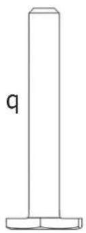
q. Leveling Feet (2)
natural_image
Illustration of six different types of bolts and fasteners, labeled a through f, with no text or symbols present.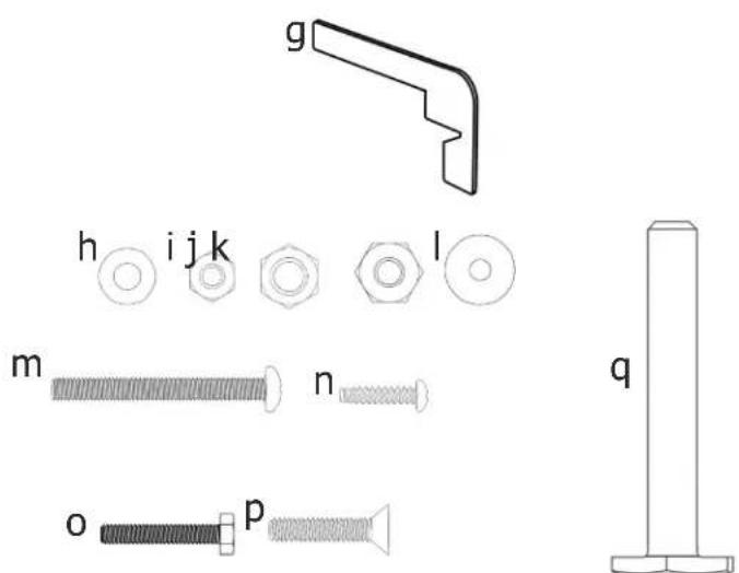
NOTE: The DELTA® 36-T30 13 and 36-T50 13 are designed to be used with a variety of DELTA® table saws. It is also possible to install this fence on non-DELTA® saws. This kit contains a variety of hardware types and sizes, not all of which are necessary to attach this fence to your specific saw. Use the hardware that best fits your saw and enables you to attach the fence rails and guide tube securely to the saw.
ASSEMBLY
UNPACKING AND CLEANING
Carefully unpack the machine and all loose items from the shipping container(s). Remove the rust-preventative oil from unpainted surfaces using a soft cloth moistened with mineral spirits, paint thinner or denatured alcohol.
CAUTION:
Do not use highly volatile solvents such as gasoline, naphtha, acetone or lacquer thinner for cleaning your machine. After cleaning, cover the unpainted surfaces with a good quality household paste wax.
WARNING:
To reduce the risk of injury, turn unit off and disconnect it from power source before installing/removing accessories, adjusting, or making repairs. An accidental start-up can cause injury.
TOOLS REQUIRED
5/32" Hex Wrench (supplied)
3/16" Hex Wrench (supplied)
Rail Alignment Gauge (supplied)
Standard Screwdriver (not supplied)
Phillips Screwdriver (not supplied)
Adjustable Wrench (not supplied)
1/4" Drill and Drill Bit (not supplied)
INSTALL FRONT GUIDE RAIL
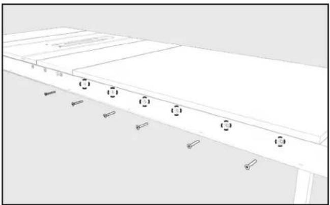
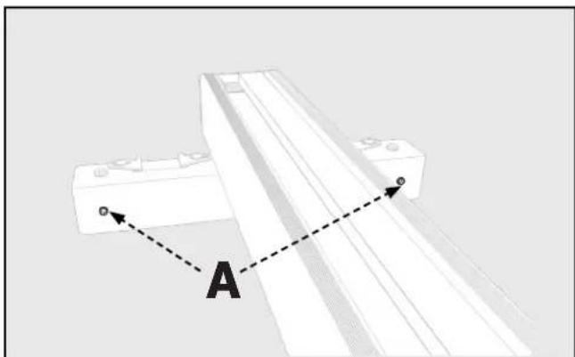
- With the left edge of the Front Guide Rail (1) near the edge of the Left Extension Wing, align the Two Holes in the table with the Two Holes in the Front Guide Rail, as indicated at location "A" in Figure 3.
- Secure the Front Guide Rail to the table with two 5/16" Countersunk Screws (c), 5/16" External Tooth Lock Washers (a), and 5/16" Hex Flange Nuts (b). Finger tighten only.
- Ensure the Front Guide Rail is parallel to the cast iron Table Top by using the rail Alignment Gauge (g) to check the distance from the top surface of the Front Guide Rail to the top of the table at both sides of the Saw Table.
- Attach the remaining Countersunk Screws (c) through the holes in the Front Guide Rail and Extension Wings using External Tooth Lock Washers (a) and Hex Flange Nuts (b) as needed. Ensure the Extension Wings are level with the cast iron Table Top.
- Tighten all hardware securing the Front Guide Rail to the Table Top.
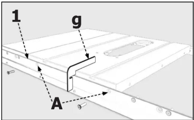
FIGURE 3
NOTE: The Front Guide Rail and Rear Guide Rail of the 36-T50, have additional holes in the Extension End that are used to attach an Extension Table. If you plan to install an Extension Table to your Table Saw, install it before attaching the Guide Tube. Based on your saw model some holes in the Front Guide Rail and Rear Guide Rail may not be used.
ATTACH REAR GUIDE RAIL
- With the edge of the Rear Guide Rail (2) near the edge of the Left Extension Wing, align the Two Holes in the table with the Two Holes in the Rear Guide Rail, as indicated at location "A" in Figure 4.
- Secure the Rear Guide Rail to the table with two 5/16" Hex Socket Screws (e), 5/16" External Tooth Lock Washers (a), and 5/16" Hex Flange Nuts (b). Finger tighten only.
- Ensure the Rear Guide Rail is parallel to the cast iron Table Top by using the rail Alignment Gauge (g) to check the distance from the top surface of the Rear Guide Rail to the top of the table at both sides of the Saw Table.
- Attach the remaining Hex Socket Screws (e) through the holes in the Rear Guide Rail and Extension Wings using External Tooth Lock Washers (a) and Hex Flange Nuts (b) as needed. Ensure the Extension Wings are level with the cast iron Table Top.
- Tighten all hardware securing the Rear Guide Rail to the Table Top.
RE-ATTACHING AN EXISTING EXTENSION WING
If your table saw has an extra extension wing that was removed when you disassembled the old fence rails, re-install it now.
ATTACHING AN ADDITIONAL EXTENSION WING
If you purchased an additional Extension Wing, install it now using the hardware included with the fence.
- Fasten the new Extension Wing to the existing wing using three 5/16" Hex Socket Screws (e), 5/16" External Tooth Lock Washers (a), and 5/16" Hex Flange Nuts (b).
- Secure the Front Guide Rail to the new Extension Wing with 5/16" Countersunk Screws (c).
- Attach the Rear Guide Rail to the new Extension Wing using Hex Socket Screws (e), External Tooth Lock Washers (a), and Hex Flange Nuts (b) as needed.
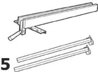
CONSTRUCTING AND ATTACHING A WOODEN TABLE SUPPORT
(For use with the DELTA® 36-T50 _T3 Fence Kit only)
Due to the extended length of the DELTA ^® 36-T50 _th rails, it is necessary to build a Wooden Table support to position and support oversized workpieces.
To build a Wooden Table support, refer to Figure 5.
Accessory Extension Table 36-T53 is available for use with the 36-T50 _T3 only.
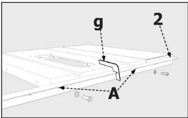
FIGURE 4
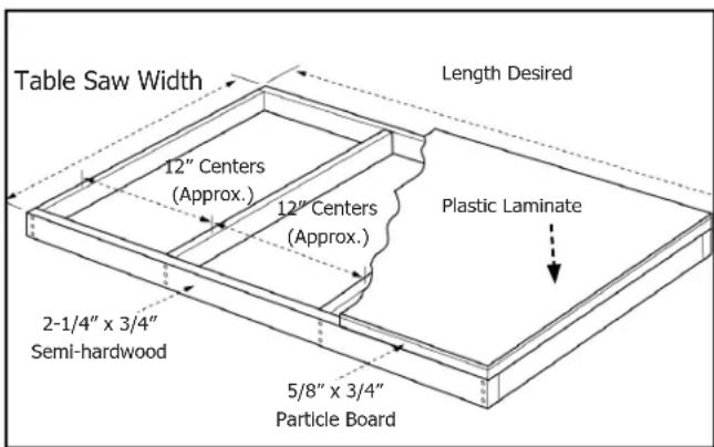
FIGURE 5
ASSEMBLY
Attach the Table Legs (5) to the Extension Table (6) as shown in Figure 6.
- Lay the Extension Table (6) upside down on the floor or on a bench.
- Position the Table Leg (5) in the corner of the Extension Table (6) as shown in Figure 6.
- Attach the Table Leg to the Table Board with four #8 x 3/4" Wood Screws (n). Drill a 1/4" hole through the two holes in the Bracket (A) and through the Table Skirt. Secure the Table Leg to the Table Skirt using 10-32 x 1-3/4" Pan Head Bolts (m), 7/32 x 1/2" Flat Washer (h), and #10-32" Hex Nut (k).
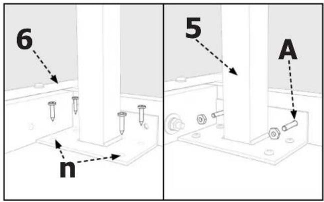
FIGURE 6
Next, attach the Threaded Leveling Feet to each leg as shown in Figure 7.
- Assemble the 3/8-16" Hex Nut (j) onto Leveling Feet (q).
- Thread the Leveling Feet into bottom of Table Leg (5).
- Repeat Steps 1 & 2 for the other Foot Assembly.
NOTE: Height adjustment will be made later.
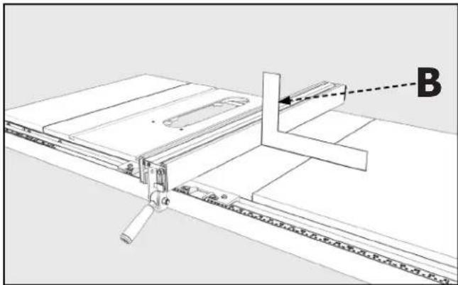
- Place Table Assembly (6) in position between the two rails as shown in Figure 8. Make sure the Saw Table Edge (B) is flush against edge of the Extension Table.
- Using a Straight Edge (C), make sure the Extension Table is in the same plane and level with Saw Table. If necessary, lightly tap up or down and adjust Leveling Feet to bring Extension Table level with Saw Table.
- Use Bar Clamps to secure the Extension Table to the Front and Rear Guide Rails as shown in Figure 9.
- Using the Holes in the Front and Rear Guide Rails, shown in Figure 9, as a template, drill 1/4" holes through the front and rear of the Extension Table.
- Secure the Extension Table to the Front Guide Rail using 1/4-20 x 1-1/2" Countersunk Screws (p), 5/16 x 5/8" Flat Washers (l), and 1/4-20" Hex Nuts (i). Secure the Extension Table to the Rear Guide Rail using 1/4-20 x 1-1/2" Hex Head Screw (o) with the same Flat Washers (l) and Hex Nuts (i) that were used for the Front Guide Rail.
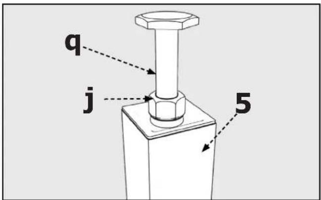
FIGURE 7
natural_image
Architectural floor plan showing a building facade with windows and doorways (no text or labels)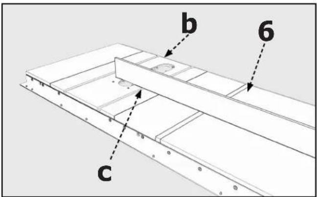
FIGURE 8FIGURE 9
ASSEMBLY
ATTACH GUIDE TUBE
- Attach the Fence Guide Tube (3) to the Front Guide Rail (1) using four (for 30" versions) or six (for 52" versions) 1/4" Pan Head Screw With Washer (d) through the Holes (B) on the bottom side of the Front Rail.
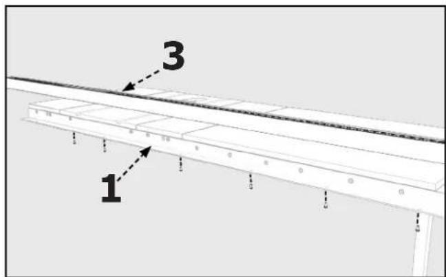
FIGURE 10
NOTE: If you removed the Spreader Bar when disassembling the old fence system, re-install it now.
INSTALL THE FENCE
- Place the Fence (4) on the Guide Tube (3) and lift the Clamping Lever (A).
- Guide the Fence over the Rear Guide Rail (2), as shown in Figure 11, and gently push the Fence on the Guide Tube (3).
Make sure that the clip on the back of the Fence engages the Rear Guide Rail.
- Push down on fence Clamping Lever to lock the Fence in place.
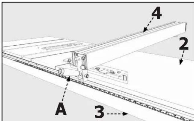
FIGURE 11
OPERATION AND ADJUSTMENTS
⚠ WARNING: To reduce the risk of injury, turn unit off and disconnect it from power source before installing/removing accessories, adjusting, or making repairs. An accidental start-up can cause injury.
ALIGNING THE FENCE TO THE MITER GAUGE SLOTS
- Move the Fence (4) until the bottom edge of the Fence is in line with the edge of one of the Miter Gauge Slots (C).
- Push down on the Fence Clamping Lever (B) to lock the Fence in place. The edge of the Fence should be parallel to the Miter Gauge Slot.

FIGURE 12
OPERATION AND ADJUSTMENTS
TO ADJUST:
- Lift the fence Clamping Lever and remove the Fence.
- Slightly tighten or loosen one of the two Set Screws (A) shown in Figure 13, using a 3mm Hex Wrench (not supplied).
IMPORTANT: Very little movement of the set screws is necessary to adjust the Fence.
- Place the Fence on the Guide Tube and check the alignment again.
- Repeat Steps 1-3 until the Fence edge is parallel to the Miter Gauge Slot.
natural_image
Pure mechanical assembly diagram showing a bracket with labeled point A and dashed line indicating alignment (no text or symbols beyond labels)FIGURE 13
SQUARING THE FENCE TO THE TABLE
WARNING:
To reduce the risk of injury, turn unit off and disconnect it from power source before installing/removing accessories, adjusting, or making repairs. An accidental start-up can cause injury.
- Lock the Fence in place on the Table.
- Using a T-Square (B) placed against the middle of the fence, check to see if the Fence is perpendicular to the table as shown in Figure 14.
natural_image
Technical line drawing of a mechanical assembly with labeled component B (no text or symbols beyond label)FIGURE 14
TO ADJUST:
- To adjust, locate the two Nylon Set Screws (C) on top of the Fence shown in Figure 15.
- Using a Flat-Head Screwdriver, rotate the Nylon Set Screws to bring the Fence perpendicular to the Table.
- Re-check the alignment and continue to adjust the Screws until the Fence edge is perpendicular to the Table.
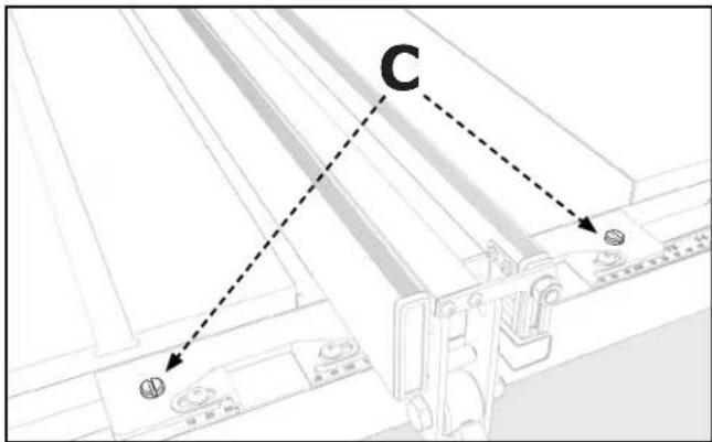
FIGURE 15
OPERATION AND ADJUSTMENTS
ADJUSTING TENSION ON THE FENCE CLAMPING LEVER
WARNING:
To reduce the risk of injury, turn unit off and disconnect it from power source before installing/removing accessories, adjusting, or making repairs. An accidental start-up can cause injury.
When the Fence is in place against the Guide Tube and the Fence Clamping Lever (A) is locked, the Fence Assembly (4) should not move. If the Fence does move or if the Lever must be forced down, the tension on the Fence Clamping Lever must be adjusted. Do the following:
- Lift the Fence Clamping Lever and remove the Fence.
- Locate the two Adjusting Screws (A), shown in Figure 13.
- Use a 3mm Hex Wrench (not supplied) to adjust the Screws.
a. If the Fence Clamping Lever is too loose, tighten the Adjusting Screws.
b. f the Fence Clamping Lever is too tight, loosen the Adjusting Screws.
NOTE: Both Screws need to be adjusted in an equal amount.
- Place the Fence on the Guide Tube and check again to see if the Fence Assembly clamps easily and holds securely.
- Continue to make adjustments as needed.
IMPORTANT: After adjusting the Fence Clamping Lever, ensure the Fence is parallel to the Miter Gauge Slot. Adjust as necessary.
ADJUSTING THE SCALE POINTER
The Pointer (C) indicates the distance between the inside face of the Fence and the Blade. To check the position of the Pointer:
- Place the fence on the Guide Tube and note the position indicated on the Pointer.
- Lock the Fence in place by pushing down on the Fence Clamping Lever.
- Following the safety instructions in your Table Saw Manual, make a sample cut.
- Measure the cut piece to ensure it to be the same as the distance indicated by the Pointer. If the piece is incorrect, the Pointer position must be adjusted. To do this:
NOTE: Do not unlock the Fence Clamping Lever or attempt to move the Fence.
a. Loosen the two Screws (D) and manually move the Pointer so that it matches the length of your sample cut.
b. Tighten the two Screws and move the Fence to the opposite side of the blade to repeat above steps with the second Pointer.
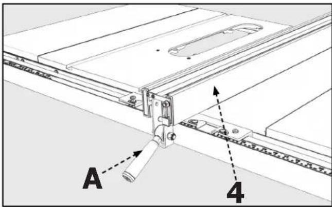
FIGURE 16
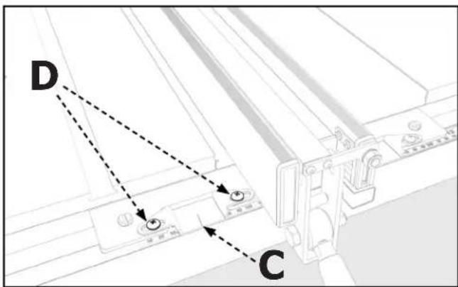
FIGURE 17
TROUBLESHOOTING
For assistance with your machine, visit our website at www.DeltaMachinery.com for a list of service centers or call Delta Power Equipment Customer Care at 1-800-223-7278.
MAINTENANCE
To reduce the risk of injury, turn unit off and disconnect it from power source before installing/removing accessories, adjusting, or making repairs. An accidental start-up can cause injury.
KEEP MACHINE CLEAN
Periodically blow out all air passages with dry compressed air. All plastic parts should be cleaned with a soft damp cloth. NEVER use solvents to clean plastic parts. They could possibly dissolve or otherwise damage the material.
Wear certified safety equipment for eye, hearing and respiratory protection while using compressed air.
For best performance use a shop vacuum or blower to keep saw blade area, the dust collection system, the guarding system and rails free of saw dust and other debris.
Wear certified safety equipment for eye, hearing and respiratory protection while using compressed air.
Specific areas which require regular maintenance include:
RIVING KNIFE CLAMP PLATE: Keep this area free of dust and debris buildup. Blow out area regularly with compressed air.
NOTE: If the riving knife clamp can't move freely, have the saw serviced by authorized DELTA® Power Equipment Corporation service center personnel.
WORM GEARS: Keep the worm gears free of dust and debris buildup. Blow out area regularly with compressed air. Use a lithium-based multipurpose grease as needed on these gears.
CLEAN SAWDUST BUILDUP OUT OF CABINET PERIODICALLY: NOTE: Debris can also be removed from the saw from below the throat plate, inside the dust port.
LUBRICATION & RUST PROTECTION
Apply hardwood flooring paste wax to the machine table occasionally or use a commercially available protective product designed for this purpose. Follow the manufacturer's instructions for use and safety.
To clean cast iron tables of rust, you will need the following materials: a medium sized scouring pad, a can of spray lubricant and a can of degreaser. Apply the spray lubricant and polish the table surface with the scouring pad. Degrease the table, then apply the protective product as described above.
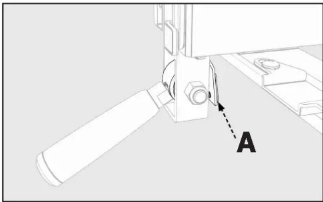
FENCE LUBRICATION
- Apply Paste Wax to the Fence and the Guide Tube sliding surfaces weekly.
- Occasionally apply Grease to the Cam Lock, and the Cam Foot (A), shown in Figure 18, to prevent wear.
natural_image
Technical diagram of a mechanical assembly with labeled component A (no text or symbols beyond label)FIGURE 18
ACCESSORIES
For accessories please visit our Web Site for an on-line catalog or for the name or your nearest supplier.
⚠ WARNING: Since accessories other than those offered by DELTA® have not been tested with this product, use of such accessories could be hazardous. For safest operation, only DELTA® recommended accessories should be used with this product.
PARTS, SERVICE OR WARRANTY ASSISTANCE
All DELTA ^® Machines and accessories are manufactured to high quality standards and are serviced by a network of an Authorized Service Centers. To obtain additional information regarding your product or to obtain parts, service, warranty assistance, or the location of the nearest service center, please call 1-800-223-7278.
Two Year Limited Warranty
- WHAT IS COVERED. Delta Power Equipment Corporation ("Company") will, at its option, repair or replace this product, if purchased at retail in the United States or Canada and the product, with normal use, has proven to be defective in workmanship or material, subject to the conditions stated in this Limited Warranty. This Limited Warranty covers only materials and labor. All transportation costs are Customer's responsibility.
- WARRANTY PERIOD. All warranty claims must be submitted within two years from the date of retail purchase. For all service parts and factory refurbished products, the warranty period is 180 days.
- HOW TO OBTAIN SERVICE. To obtain warranty service, you must return the defective product, at your expense, to a service center authorized by Company to perform warranty service (a "Company Authorized Service Center") within the applicable warranty period, together with acceptable proof of purchase, such as your original receipt bearing the date of purchase, or product registration number. Company reserves the right to restrict warranty claim service to the country where the purchase was made and/or to charge for the cost to export service parts or provide warranty service in a different country. For this purpose, on-line purchases are deemed made in the United States. For the location of your nearest Company Authorized Service Center, call Company's Customer Care Center at (800) 223-7278.
4. EXCLUSIONS.
- Company does not offer any warranty on products purchased in used or damaged condition.
- Company does not warrant any products purchased outside the United States or Canada.
- Company will not be responsible for any damage that has resulted from normal wear, misuse, abuse or any repair or alteration made by anyone other than a Company Authorized Service Center or a designated representative of Company's Customer Care Center.
All IMPLIED WARRANTIES are expressly limited to the warranty period identified above.
Company will not be liable for INCIDENTAL OR CONSEQUENTIAL damages.
This limited warranty is Company's sole warranty and sets forth the customer's exclusive remedy with respect to defective products; all other warranties, express or implied, whether of merchantability, fitness for purpose, or otherwise, are expressly disclaimed by Company, except as expressly stated in this warranty statement.
Some states do not allow the exclusion or limitation of incidental or consequential damages, or the limitation of implied warranties, so the above limitations or exclusions may not apply to you. This warranty gives you specific legal rights and you may have other rights which vary in certain states or provinces. For further details of warranty coverage and warranty repair information, call (800) 223-7278. To register your products on-line, we encourage you to visit our website and register for a FREE DELTA® Member Account at http://www.deltamachinery.com/register.
LATIN AMERICA: This warranty does not apply to products sold in Latin America. For products sold in Latin America, call the local company or see website for warranty information.
REPLACEMENT PARTS
Use only identical replacement parts. For a parts list or to order parts, visit our website at www.DeltaMachinery.com/service. You can also order parts from your nearest Authorized Warranty Service Center or by calling Technical Service Manager at 1-800-223-7278 to receive personalized support from one of our highly-trained representatives.
FREE WARNING LABEL REPLACEMENT
If your warning labels become illegible or are missing, call 1-800-223-7278 for a free replacement.
SERVICE AND REPAIRS
All quality tools will eventually require servicing and/or replacement of parts. For information about Delta Power Equipment Corporation, its factory-owned branches, or to locate an Authorized Warranty Service Center, visit our website at www.DeltaMachinery.com/service or call Customer Care at 1-800-223-7278. All repairs made by our service centers are fully guaranteed against defective material and workmanship. We cannot guarantee repairs made or attempted by others. By calling this number you can also find answers to most frequently asked questions 24 hours/day.
You can also write to us for information at Delta Power Equipment Corporation, 2651 New Cut Road, Spartanburg, SC 29303 Attention: Technical Service Manager. Be sure to indicate all of the information shown on the nameplate of your saw (model number, type, serial number, date code, etc.).
SOMMAIRE
DESCRIPTION FONCTIONNELLE 14
INSTRUCTIONS DE SECURITE IMPORTANTES .....15
CONSIGNES DE SECURITE – DEFINITIONS .....15
REGLES GENERALES DE SECURITE ....16
CONTENU DES CARTONS ....17
ASSEMBLAGE ....18
UTILISATION ET REGLAGES 21
DEPANNAGE 24
ENTRETIEN 24
ACCESSOIRES 25
GARANTIE 25
SERVICE APRES-VENTE ET REPARATIONS ....2 5
PIÈCES DE REMPLACEMENT 25
FRENCH....14
SPANISH 26
DESCRIPTION FONCTIONNELLE
natural_image
Technical line drawings of two mechanical components labeled 4 and 5 (no text or symbols on the parts themselves)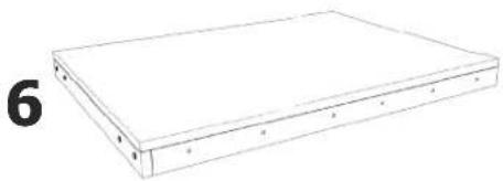
natural_image
Simple line drawing of a rectangular electronic device with labeled pins (no text or symbols on the device itself)PACKET DE MATÉRIEL
natural_image
Architectural floor plan showing a building with windows and door placements (no text or labels)FIGURE 9
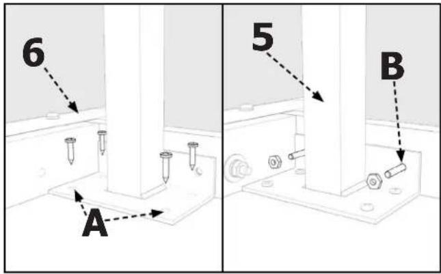
FIGURE 6
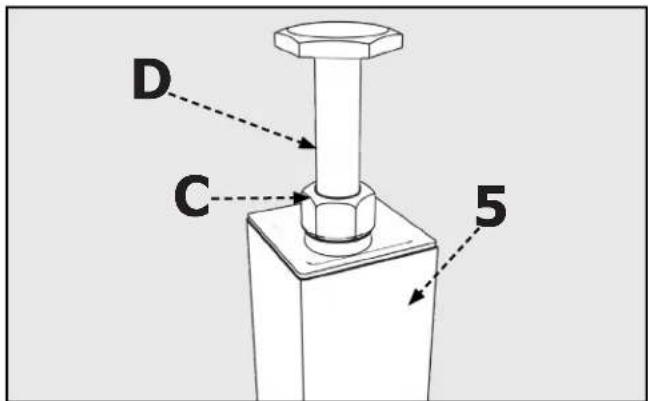
FIGURE 7
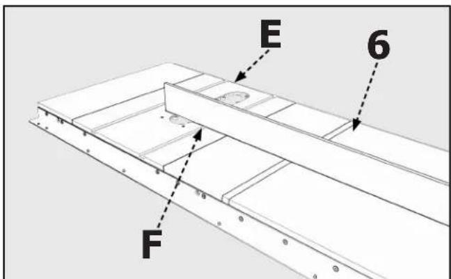
FIGURE 8
ASSEMBLAGE
ATTACHER LE TUBE DU GUIDE
natural_image
Diagram of a mechanical assembly with labeled component 'A' and directional arrows (no text or symbols beyond labels)FIGURE 13
REGLAGE PERPENDICULAIRE DU GUIDE SUR L'ETABLI
AVERTISSEMENT :
natural_image
Technical line drawing of a mechanical assembly with labeled component B (no text or symbols beyond label)FIGURE 14
REGLAGE:
natural_image
Technical diagram of a mechanical assembly with labeled component A (no text or symbols beyond label)FIGURA 18
ACCESSOIRES
ASSISTANCE POUR PIÈCES, SERVICE OU GARANTIE
natural_image
Simple line drawing of a rectangular electronic device with mounting holes (no text or symbols)a
b

C
d
e
1
h

ijk


1
m
n

0
p

4
natural_image
Technical line drawings of two mechanical components: a flat beam and a flanged rod (no text or symbols)ENSAMBLAJE
CONTENIDO DE LA CAJA
natural_image
Architectural floor plan showing horizontal beam and supports with circular markers (no text or labels)FIGURA 9
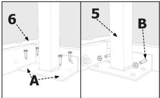
FIGURA 6
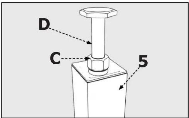
FIGURA 7
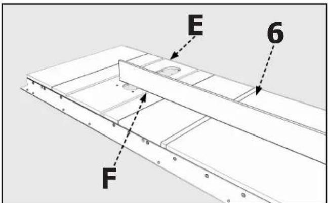
FIGURA 8
ENSAMBLAJE
ACOPLAR EL TUBO GUÍA
natural_image
Technical diagram showing a mechanical assembly with labeled point A and dashed line indicating alignment (no text or symbols beyond labels)FIGURA 13
CUADRAR LA GUÍA CON LA MESA
natural_image
Technical line drawing of a mechanical assembly with labeled component B (no text or symbols beyond label)FIGURA 14
PARA AJUSTAR:
natural_image
Technical diagram of a mechanical assembly with labeled component A (no text or symbols beyond label)FIGURA 18
ACCESORIOS
©Copyright 2020 Delta Power Equipment Corporation
DPEC006280
Rev:3
03/05/2020


- TABLE OF CONTENTS
- FUNCTIONAL DESCRIPTION
- PROPOSITION 65 WARNING:
- IMPORTANT SAFETY INSTRUCTIONS
- WARNING: CAREFULLY READ AND FOLLOW ALL WARNINGS AND INSTRUCTIONS ON YOUR PRODUCT AND IN THIS MANUAL. SAVE THIS MANUAL. MAKE SURE ALL USERS ARE FAMILIAR WITH IT'S WARNING
- SAFETY LOGOS
- DANGER:
- WARNING:
- CAUTION:
- GENERAL POWER TOOL SAFETY WARNINGS
- Work area safety
- Electrical safety
- Personal safety
- Power tool use and care
- Service
- CARTON CONTENTS
- HARDWARE PACKAGE
- (included with the 36-T30 _T3 )
- (included with the 36-T50 _13 )
- ASSEMBLY
- UNPACKING AND CLEANING
- TOOLS REQUIRED
- INSTALL FRONT GUIDE RAIL
- ATTACH REAR GUIDE RAIL
- RE-ATTACHING AN EXISTING EXTENSION WING
- ATTACHING AN ADDITIONAL EXTENSION WING
- CONSTRUCTING AND ATTACHING A WOODEN TABLE SUPPORT
- ATTACH GUIDE TUBE
- INSTALL THE FENCE
- OPERATION AND ADJUSTMENTS
- ALIGNING THE FENCE TO THE MITER GAUGE SLOTS
- TO ADJUST:
- SQUARING THE FENCE TO THE TABLE
- ADJUSTING TENSION ON THE FENCE CLAMPING LEVER
- ADJUSTING THE SCALE POINTER
- TROUBLESHOOTING
- MAINTENANCE
- KEEP MACHINE CLEAN
- LUBRICATION & RUST PROTECTION
- FENCE LUBRICATION
- ACCESSORIES
- PARTS, SERVICE OR WARRANTY ASSISTANCE
- Two Year Limited Warranty
- EXCLUSIONS.
- REPLACEMENT PARTS
- FREE WARNING LABEL REPLACEMENT
- SERVICE AND REPAIRS
- SOMMAIRE
- DESCRIPTION FONCTIONNELLE
- PACKET DE MATÉRIEL
- ASSEMBLAGE
- ATTACHER LE TUBE DU GUIDE
- REGLAGE PERPENDICULAIRE DU GUIDE SUR L'ETABLI
- AVERTISSEMENT :
- REGLAGE:
- ACCESSOIRES
- ASSISTANCE POUR PIÈCES, SERVICE OU GARANTIE
- ENSAMBLAJE
- CONTENIDO DE LA CAJA
- ACOPLAR EL TUBO GUÍA
- CUADRAR LA GUÍA CON LA MESA
- PARA AJUSTAR:
- ACCESORIOS
Brand : DELTA
Model : 36-T30
Category : Saw