Edge 2Bike - Bike accessory Saris - Free user manual and instructions
Find the device manual for free Edge 2Bike Saris in PDF.

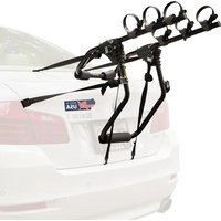
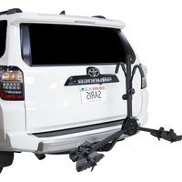
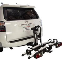
| Product type | Hitch bike rack |
| Brand | Saris |
| Model | Edge 2Bike |
| Capacity | 2 bikes |
| Maximum load per bike | 36 kg (80 lbs) |
| Total supported weight | 72 kg (160 lbs) |
| Minimum wheel size | 24 inches |
| Maximum wheel size | 29 x 3 inches or 27.5 x 5 inches |
| Maximum wheelbase | 135 cm (53 inches) |
| Hitch type | Standard hitch receiver (class II/III) |
| Foldable | Yes, with tilt lever |
| Locking system | Hitch pin + integrated locking cables |
| Warranty | Limited lifetime (original purchaser, North America) |
| Recommended maintenance | Soap and water cleaning every 90 days; wax-based lubricant for arms |
| Use | Road only, max 113 km/h (70 mph) |
| Country of origin | Not specified |
Frequently Asked Questions - Edge 2Bike Saris
User questions about Edge 2Bike Saris
0 question about this device. Answer the ones you know or ask your own.
Ask a new question about this device
Download the instructions for your Bike accessory in PDF format for free! Find your manual Edge 2Bike - Saris and take your electronic device back in hand. On this page are published all the documents necessary for the use of your device. Edge 2Bike by Saris.
USER MANUAL Edge 2Bike Saris
| LETTER QTY PART DESCRIPTION | ||
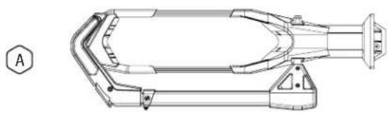
| A 1 Front tray A | ||
| B 1 Rear tray B | ||
| C 1 Rear tray C | ||
| D 1 Front tray D | ||
| E 1 Spine | ||
| F 16 M8 x 1.25 – 25mm bolt | ||
| G 1 5mm hex wrench | ||
| H 1 Hitch pin | ||
| I 1 Hich pin lock | ||
| J 2 | Keys | |
natural_image
Technical line drawing of a mechanical component with no visible text or symbols
natural_image
Technical line drawing of a mechanical component with no visible text or symbols
natural_image
Technical line drawing of a mechanical component with no visible text or symbols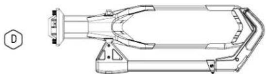
natural_image
Technical line drawing of a mechanical component with no visible text or symbols
natural_image
Technical line drawing of a mechanical lever assembly (no text or symbols)
natural_image
Three technical diagrams showing a bolt, a nut, and a bent pipe (no text or labels)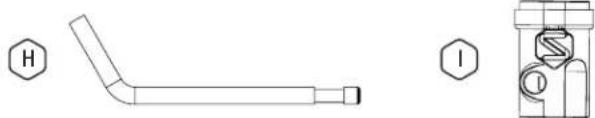
natural_image
Technical drawing of a bent pipe with cross-section view showing internal components (no text or labels)
FOLLOW INSTRUCTIONS

VIEW OUR INSTALLATION VIDEO
Saris.com/en/instructional-videos-1.html

REGISTER YOUR PRODUCTS FOR UPDATES
Saris.com/registration

RELEVANT PATENTS
Saris.com/patents

TELL US WHAT YOU THINK
Saris.com/feedback

CUSTOMER SUPPORT
1-800-783-7257
support@saris.com
saris.com
LOT CODE
ASSEMBLE RACK ATTACH TO VEHICLE
NOTE: Assembly of this rack may be easier while the spine is in your vehicle's hitch.
text_image
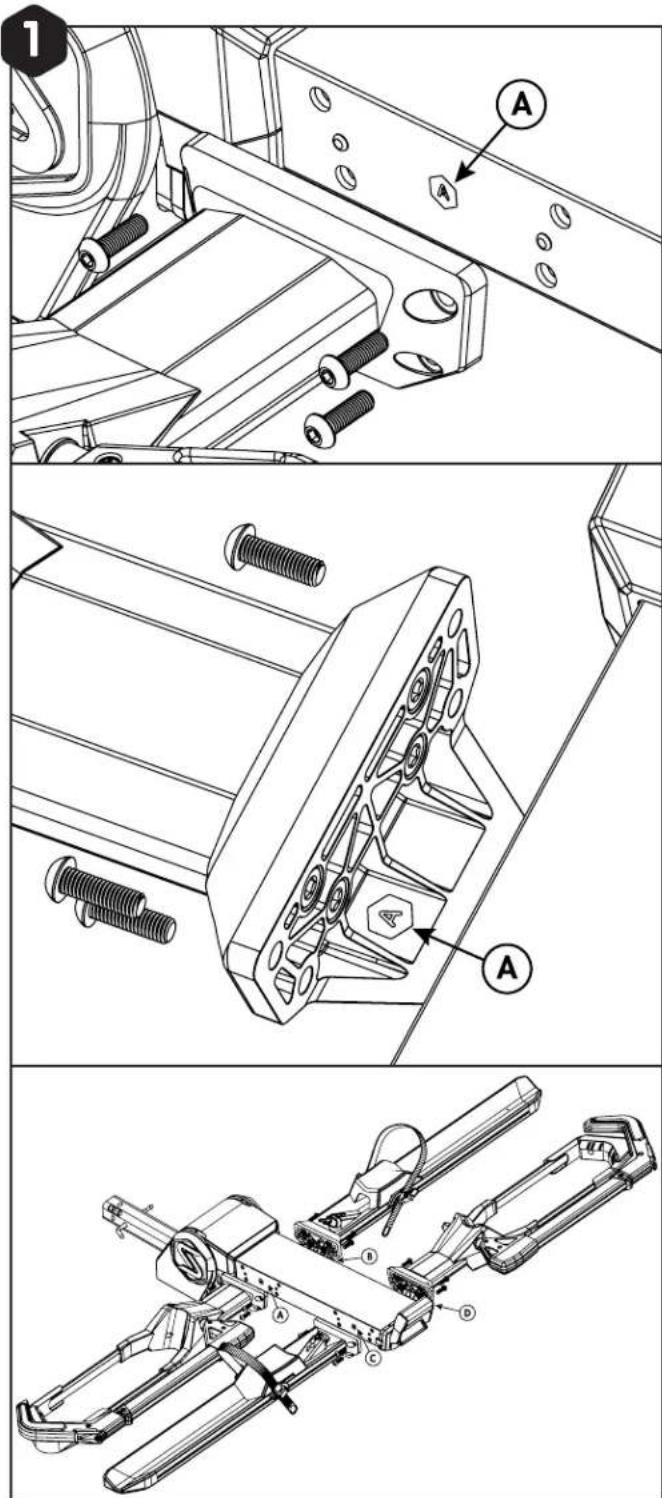
Technical diagram showing mechanical assembly steps with labeled parts A and B, including exploded and assembled views.Match the letters on the end of each tray to the letters on the side of the hitch spine. Secure with M8 bolts and torque to 12N•M, as shown.
natural_image
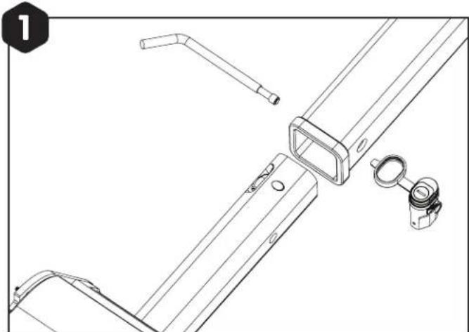
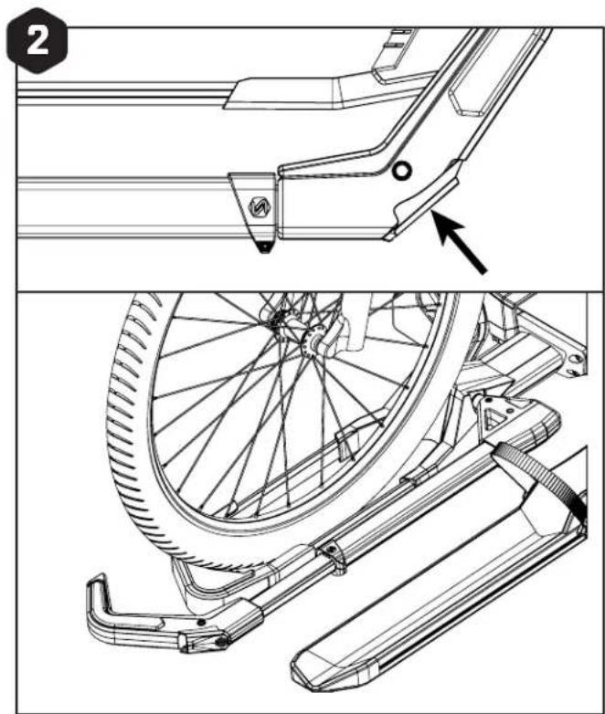
Technical line drawing of a mechanical bracket assembly with mounting holes and a separate inset view (no text or symbols)Insert the rack into your hitch, matching the holes on your vehicle's receiver to the holes in the rack.
natural_image
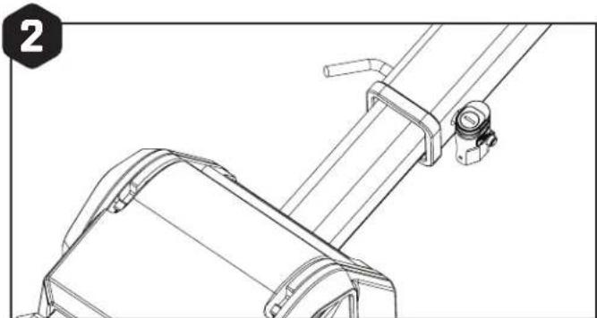
Technical line drawing of a mechanical assembly with no visible text or symbolsInstall the hitch pin through the receiver pinhole and attach the lock.
natural_image
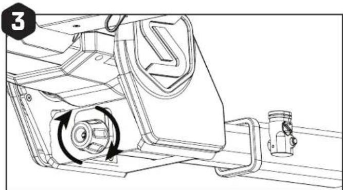
Technical line drawing of a mechanical assembly with rotating components (no text or symbols)Tighten the knob at the end of the rack base until the rack is tight in the vehicle's receiver. An extra lift on the rack while tightening the knob will ensure there is no wobble once the bikes are loaded.
natural_image
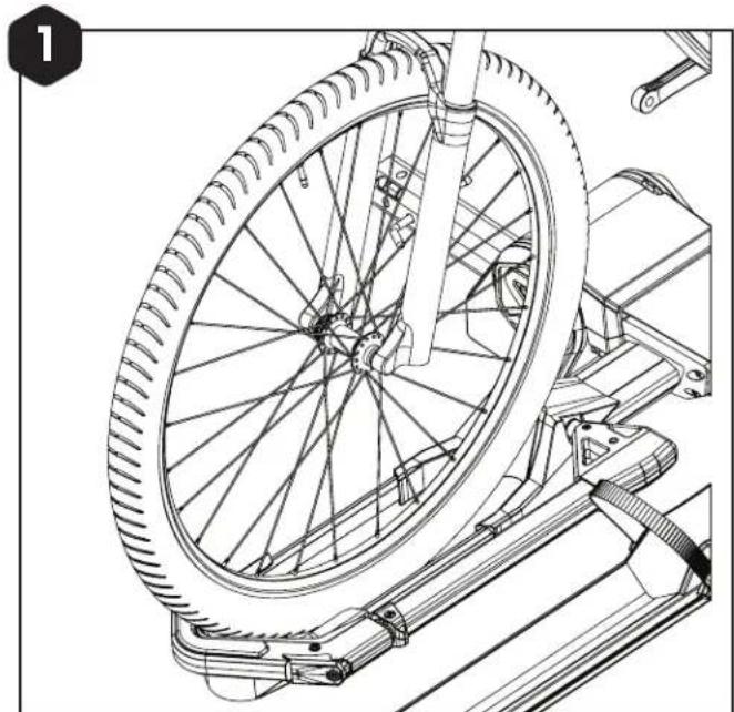
Technical line drawing of a bicycle wheel assembly with mounting bracket (no text or symbols)Place the front wheel in the wheel scoop.
Ensure tire is straight and centered between support bars.
natural_image
Technical line drawing of a bicycle wheel assembly with mounting bracket and side panel (no text or symbols)Press and hold the button at the top of the wheel hook and pull the arm out.
natural_image
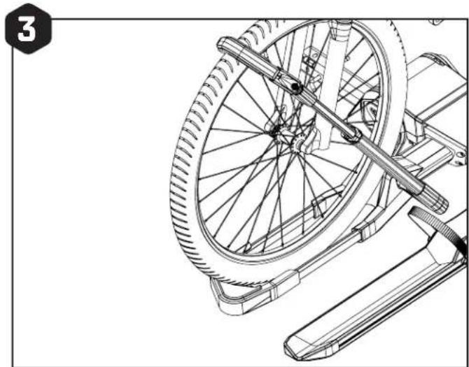
Technical line drawing of a bicycle wheel assembly with a lever mechanism (no text or symbols)Bring the arm towards the bike until it stops. Then, release the hook and press tightly against the tire.
REAR WHEEL STRAP ATTACHMENT
natural_image
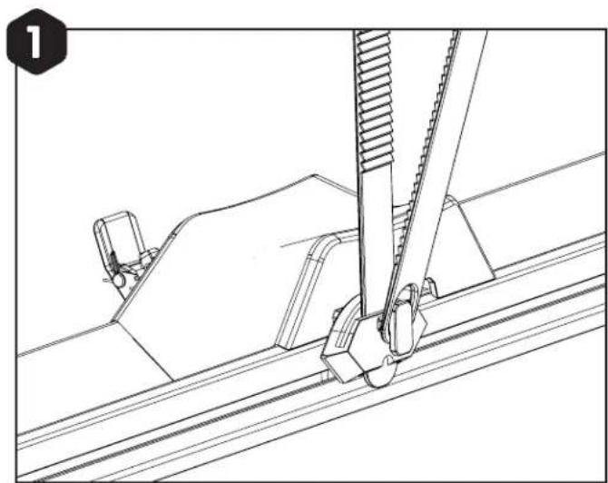
Technical line drawing of a mechanical assembly with a tool and bracket (no text or symbols)NOTE: For easy strap management while loading bikes, loop the end of the strap around the hook to get it out of the way.
Clean any mud, dirt, and debris from the rim before tightening the strap.
REAR WHEEL STRAP ATTACHMENT HATCH ACCESS
natural_image
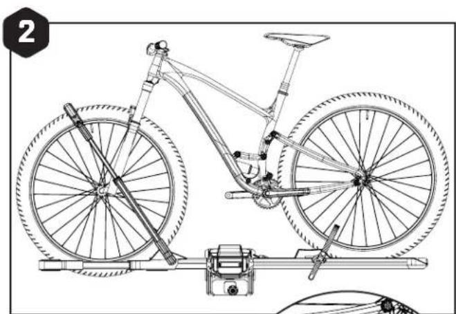
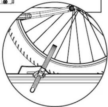
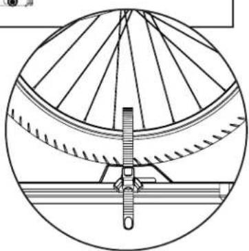
Line drawing of a bicycle mounted on a wheeled platform with visible wheel and suspension components (no text or symbols)Slide rear wheel block against the inside of tire. Slide strap carriage toward the tire until it stops. Insert strap through buckle. Pull tight to secure.
natural_image
Technical line drawing of a bicycle wheel assembly (no text or symbols)
natural_image
Technical line drawing of a mechanical device with gears and levers (no text or symbols)For hatch access with bikes installed on the rack, pull the lever at the end of the rack to tilt away. Use caution and be sure to support the weight of the bikes and rack when tilting away.
NOTE: We strongly recommend a second person to help with lowering the rack with bikes installed.
Folding: Pull lever and lift rack to fold up against the vehicle.
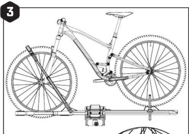
natural_image
Line drawing of a bicycle with front wheel, suspension frame, and support structure (no text or symbols)For additional handlebar clearance, set the rear wheel on top of the block and secure the strap. Be sure strap carriage is centered on the wheel.
natural_image
Technical line drawing of a mechanical assembly with radial blades and a central pivot (no text or symbols)LOCK BIKES
text_image
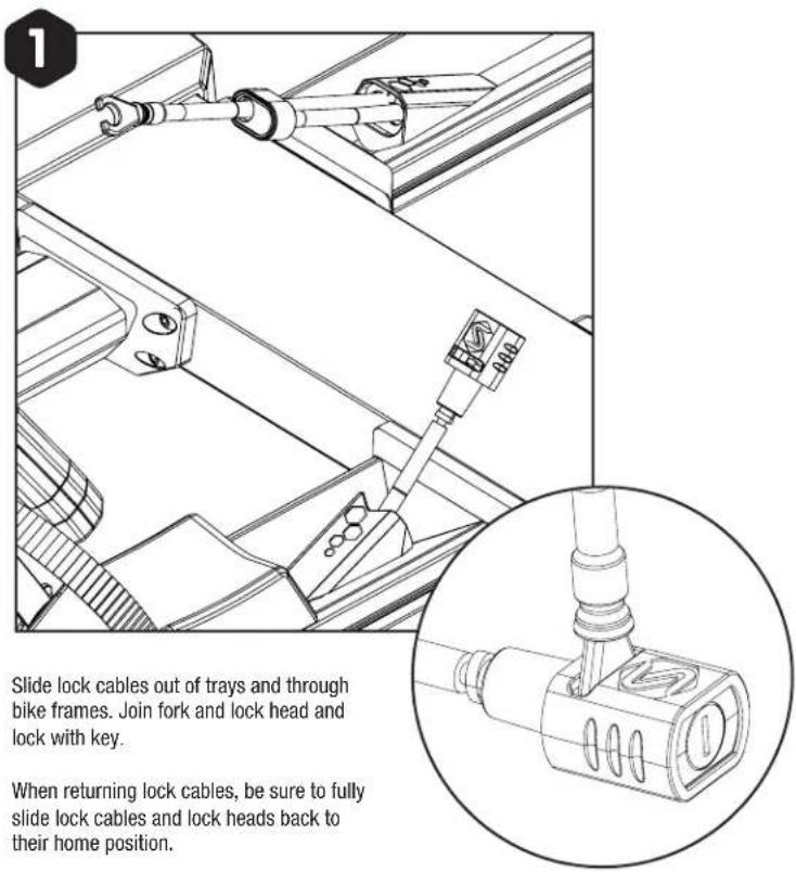
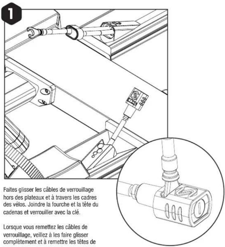
Slide lock cables out of trays and through bike frames. Join fork and lock head and lock with key. When returning lock cables, be sure to fully slide lock cables and lock heads back to their home position.Slide lock cables out of trays and through bike frames. Join fork and lock head and lock with key.
When returning lock cables, be sure to fully slide lock cables and lock heads back to their home position.
TECHNICAL SPECIFICATIONS:
Maximum bike weight per position: 80 lb.
Minimum wheel size: 24"
Maximum wheel size: 27.5 x 5" / 29" x 3"
Maximum wheelbase: 53"
MAINTENANCE AS NEEDED:
If hook arms become sticky, difficult to move, or do not retract on their own:
- Pull hook to fully extended position and clean inner arm tube.
- Flush water down inner arm tube and into the outer arm collar.
- Repeat until arm moves freely.
- Allow to dry, apply light, wax-based lubricant around the arm collar, and cycle the arm to allow the lubricant to reach the lower bushing surface.
- Wipe any excess lubricant off of the arm and collar area to prevent dirt build-up.
RECOMMENDED MAINTENANCE:
Each use:
- Check for signs of wear
- Check bike cradles and wheel scoops
- Check for loose bolts
Every 90 days:
- Clean with water and mild soap
- Lubricate locks if applicable (use wet, oil-based lubricant; NO WD-40)
CAUTIONS:
- All requirements for compatibility/fit as stated in the current Saris vehicle/carrier compatibility guide must be followed. (Available at any Saris dealer or www.saris.com). If your vehicle is not listed or you have any questions, please call our customer service at 800-783-7257 or visit www.saris.com.
- Read and follow instructions carefully. Save owner's manual for future reference or parts information. Ensure that any other users of the bicycle carrier are familiar with their content.
- Drive slowly over speed bumps, 5 to 10 mph max speed.
- It is the end user's responsibility to ensure that use of this product meets all local and state laws.
- When cleaning vehicle and rack, use only water-soluble cleaners. Do not take rack through car wash.
- Ensure rack trays are a minimum of 12" from the ground when installed on the vehicle.
- Make sure bike tires are not directly behind exhaust pipe.
- Rack must be installed directly into vehicle hitch receiver or approved Saris accessory. Do not modify the hitch receiver or use hitch extenders.
• Approved for use on Class, A, B, and C Motorhomes or RV's. The receiver hitch must directly attached to the motorhome chassis, not just to the bumper. - Not approved for use on tow-behind campers or trailers.
- Prior to usage on the road, remove all loose parts from bicycle, including (but not limited to) child seat, basket, lock, light, pump, etc.
- This carrier is not recommended for off-road use or use at speed exceeding 70 mph (113 km/h).
- The handling characteristics of a vehicle will change when a rear bicycles carrier is fitted and especially when it is loaded (in particular crosswind sensitivity, handling on bends and braking). Driving techniques should be altered to allow for these changes – reduce speed, especially on bends, and allow for longer braking distances.
- The vehicle's total length increases when the bike carrier is attached. The bikes themselves may increase the vehicle's total width and height. Take care when reversing and/or entering garages, ferries, etc.
- Remove carrier from vehicle when not in use.
- Tighten straps regularly during the journey.
- Vehicle should be in good condition in the area at which the hitch is located.
- Saris absolves itself of responsibility for any personal injuries or consequential damage to property or wealth caused by incorrect fitting or use.
- Do not exceed maximum load capacity of carrier (80 lbs max per bike tray) Secure properly and adjust for even load distribution, loading the heaviest/biggest bike first and closest to the vehicle. Minimum compatible wheel size 24". Maximum compatible wheel size: 29"x3" and 27.5" x 5". Maximum compatible wheelbase: 53".
OFFICIAL WARRANTY TERMS:
Saris Equipment, parent company of Saris Racks, warrants our products to the original consumer to be free from defects in materials and workmanship. Your purchase includes the following warranty which is in lieu of all other express warranties. This warranty is extended only to the initial consumer purchaser. This warranty gives you specific legal rights. You may have other legal rights which vary from state to state. Please retain your sales slips for your records, as proof of purchase will be required.
WARRANTY TERM:
Car Racks Limited Lifetime*
Home Storage/Bike Racks Limited Lifetime*
Parking Racks 1 year
* Warranty only valid for original purchaser. Limited lifetime warranty available in North America only.
Manufacturing defects are most likely to be identified on new products or early in the product's lifespan. Each warranty claim is unique, and it is solely up to Saris Equipment to determine if a product can be covered by the limited lifetime warranty due to defects, or if the product has suffered wear and tear.
Any product or part thereof found to be defective within the term as set forth above will be replaced without charge provided that: (1) its failure resulted from a defect in material or workmanship and not from normal wear and tear expected in the use of the product; (2) the product was not abused, misused, Improperly assembled, Improperly maintained or damaged by accident or installation of parts or accessories not originally intended or compatible with the racks as originally sold; (3) there was no failure to follow instructions or warnings in the Owner's Manual; (4) no alterations or modifications were made; and (5) the product or part is delivered, freight prepaid, to Saris Equipment or an authorized service center. Please call 1-800-783-7257 to obtain return authorization prior to return. Any other claims not included in the statements above are void and will not be honored. Saris Equipment reserves the right to inspect any product before issuing a replacement. Saris Equipment's only obligation shall be to replace such products or parts that it determines are defective.
LIMITATIONS:
THE FOREGOING WARRANTIES ARE THE ONLY WARRANTIES MADE BY SARIS EQUIPMENT. THERE ARE NO OTHER WARRANTIES. ANY WARRANTY THAT MIGHT OTHERWISE BE IMPLIED BY LAW INCLUDING, BUT NOT LIMITED TO ANY IMPLIED WARRANTY OF MERCHANTABILITY OR FITNESS FOR A PARTICULAR PURPOSE ARE LIMITED STRICTLY TO THE APPLICABLE LENGTH OF THIS LIMITED WARRANTY.
Saris Equipment shall not be liable for incidental or consequential losses, damages, or expenses in connection with its products. Saris Equipment's liability hereunder is expressly limited to the replacement of goods not complying with this warranty or, at Saris Equipment's election, to the repayment of an amount of the purchase price of the product in question.
EXCLUSIONS:
- If consumer does not comply with all warnings, cautions, or instructions listed in Instruction Manual, damage is not covered under warranty
- Impact/collision damage is not covered under warranty
- Cradles and strap damage due to improper arm placement are not covered under warranty
- Carrying anything other than a bicycle is not covered under warranty
- Rust is wear and tear and is preventable with rack maintenance
• Weather impact (UV, salt air/water)
• Damage to mounting surface - Damage or loss resulting from failure to replace/maintain consumable items not covered
• Not following Recommended Rack Maintenance -
Consumable parts are not covered by warranty. Including but not limited to:
-
Arm and wheel tray adjustment knobs
- Frame and wheel straps
- Vehicle attachment straps
- Molded wheel trays
- Frame cradles
- Threaded assemblies
- Ratcheting assemblies
© 2024 SARIS EQUIPMENT
QUÉ HAY EN LA CAJA
natural_image
Technical line drawing of a mechanical component with no visible text or symbols
natural_image
Technical line drawing of a mechanical component with no visible text or symbols
natural_image
Technical line drawing of a mechanical component with no visible text or symbols
natural_image
Technical line drawing of a mechanical component with no visible text or symbols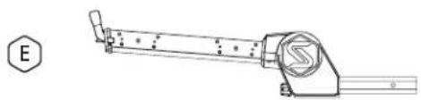
natural_image
Technical line drawing of a mechanical lever assembly (no text or symbols)
natural_image
Three technical diagrams showing a bolt, a nut, and a bent pipe (no text or labels)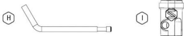
natural_image
Technical line drawing of a bent pipe with cross-section view showing internal components (no text or symbols)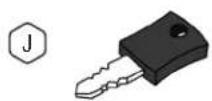
text_image
Technical diagram showing assembly steps of a mechanical component with labeled parts A and numbered annotations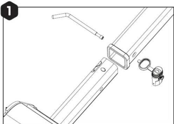
natural_image
Technical line drawing of a mechanical bracket assembly with mounting holes and a handle (no text or symbols)natural_image
Technical line drawing of a mechanical assembly with no visible text or symbolsnatural_image
Technical line drawing of a mechanical assembly with no visible text or symbolsnatural_image
Technical line drawing of a bicycle wheel assembly with mounting bracket (no text or symbols)natural_image
Technical line drawing of a bicycle wheel assembly with mounting bracket and side panel (no text or symbols)natural_image
Technical line drawing of a bicycle wheel assembly with a lever handle (no text or symbols)natural_image
Technical line drawing of a mechanical assembly with a tool and bracket (no text or symbols)natural_image
Line drawing of a bicycle mounted on a wheeled platform with visible wheel and suspension components (no text or symbols)natural_image
Technical line drawing of a bicycle wheel assembly (no text or symbols)
natural_image
Technical line drawing of a mechanical device with gears and levers (no text or symbols)natural_image
Line drawing of a bicycle with front wheel, suspension frame, and support structure (no text or symbols)natural_image
Technical line drawing of a mechanical assembly with a circular base and radial components (no text or symbols)natural_image
Technical line drawing of a mechanical component with no visible text or symbols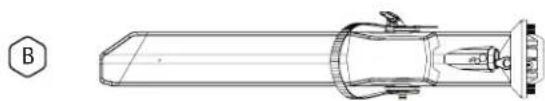
natural_image
Technical line drawing of a mechanical component with no visible text or symbols
natural_image
Technical line drawing of a mechanical component with no visible text or symbols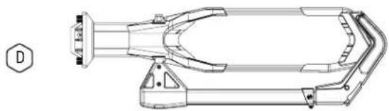
natural_image
Technical line drawing of a mechanical component with no visible text or symbols
natural_image
Technical line drawing of a mechanical lever assembly (no text or symbols)
natural_image
Three technical diagrams showing a bolt, a nut, and a bent pipe (no text or labels)
natural_image
Technical line drawing of a bent pipe with cross-section view showing internal components (no text or symbols)
SUIVRE LES INSTRUCTIONS

VOIR NOTRE VIDÉO D'INSTALLATION
Saris.com/en/instructional-videos-1.html

ENREGISTREZ VOS PRODUITS POUR
OBTENIR DES MISES À JOUR
Saris.com/registration

BREVETS PERTINENTS
Saris.com/patents

DITES-NOUS CE QUE VOUS PENSEZ
Saris.com/feedback

SOUTIEN À LA CLIENTÈLE
1-800-783-7257
support@saris.com
saris.com
CODE DU LOT
ASSEMBLER LE SUPPORT FIXATION AU VÉHICULE
text_image
Technical diagram showing assembly steps of a mechanical component with labeled parts A and numbered annotationsnatural_image
Technical line drawing of a mechanical bracket assembly with mounting holes and a handle (no text or symbols)natural_image
Technical line drawing of a mechanical assembly with no visible text or symbolsnatural_image
Technical line drawing of a mechanical assembly with no visible text or symbolsnatural_image
Technical line drawing of a bicycle wheel assembly with mounting bracket (no text or symbols)natural_image
Technical line drawing of a bicycle wheel assembly with mounting bracket and side panel (no text or symbols)natural_image
Technical line drawing of a bicycle wheel assembly with a lever handle (no text or symbols)natural_image
Technical line drawing of a mechanical assembly with a tool and bracket (no text or symbols)natural_image
Line drawing of a bicycle mounted on a wheeled platform with visible wheel and suspension components (no text or symbols)natural_image
Technical line drawing of a bicycle wheel assembly (no text or symbols)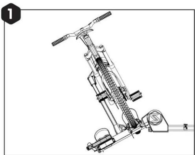
natural_image
Technical line drawing of a mechanical device with gears and levers (no text or symbols)natural_image
Line drawing of a bicycle with front wheel, suspension frame, and support structure (no text or symbols)natural_image
Technical line drawing of a mechanical assembly with no visible text or symbolsVERROUILLER LES VÉLOS
Supports de parking 1 an