DTR700 - Talkie Walkie MOTOROLA - Free user manual and instructions
Find the device manual for free DTR700 MOTOROLA in PDF.
User questions about DTR700 MOTOROLA
0 question about this device. Answer the ones you know or ask your own.
Ask a new question about this device
Download the instructions for your Talkie Walkie in PDF format for free! Find your manual DTR700 - MOTOROLA and take your electronic device back in hand. On this page are published all the documents necessary for the use of your device. DTR700 by MOTOROLA.
USER MANUAL DTR700 MOTOROLA
PROFESSIONAL DIGITAL TWO-WAY RADIO DTR600/DTR700 LIMITED KEYPAD PORTABLE RADIO USER GUIDE
en-USfr-CA
October 2019
© 2019 Motorola Solutions, Inc. All rights reserved.

MN004869A01-AB

MOTOROLA SOLUTIONS
English
Contents
Product Safety and RF Exposure Compliance. 5
Acoustic Safety. 5
Introduction. 6
Package Contents. 6
Notice to Users (FCC and Industry Canada)
Batteries and Chargers Safety Information. 8
Operational Safety Guidelines. 8
Chapter 1: Radio Overview. 10
Radio Parts. 10
Radio Specifications. 11
Status Indicators. 12
Icons. 12
Battery Features. 14
About Li-Ion Battery. 14
Battery Recycling and Disposal. 15
Installing the Li-Ion Battery. 15
Removing the Li-Ion Battery. 17
Holster. 18
Power Supply and Drop-In Tray SUC....19
Battery Life. 20
Battery Status Information. 20
Charging with the Drop-In Tray SUC.... 20
Charging a Stand-Alone Battery. 21
Estimated Charging Time. 22
Charging a Radio and Battery using a
MUC. 22
LED Indicator of Chargers. 23
Chapter 2: Getting Started. 25
Turning the Radio On or Off. 25
Adjusting Volume. 25
Browsing and Selecting Channels. 25
Chapter 3: Radio Call Features. 27
Push-To-Talk (PTT) Button 27
Talk Permit Tone (TPT) 27
Home Channel. 27
PROFILE ID. 27
Setting the Non-Interference or Privacy
Feature 28
Talk Range. 28
Programmable Button Options. 28
Private Reply. 29
English
Starting a Private Reply 29
Canceling Queues 29
Direct Call. 29
Making a Direct Call. 30
Call All Available. 30
Starting Call All Available. 31
Page All Available. 31
Starting Page All Available. 32
Scan 32
Enabling Scan. 33
Chapter 4: Contacts Management. 34
Contact List. 34
Adding New Contacts. 34
Contacts. 34
Making Calls. 35
Ending Calls. 35
Call Log. 35
Storing Call Log. 35
Chapter 5: Radio Contacts Feature. 37
Call Alert. 37
Sending Call Alerts. 37
Text Messages. 37
Sending Quick Text. 37
Receiving Messages. 38
Chapter 6: Radio Settings. 39
Adjusting Display Brightness 39
Setting Backlight Timer. 39
Setting Menu Timer. 39
Enabling All Tones. 39
Enabling Ringer Volume. 40
Enabling Vibrate. 40
Enabling Ringer Tone. 40
Enabling Keypad Tone. 41
Enabling Power Up Tone. 41
Selecting Mic Gain for Radio. 41
Selecting Mic Gain for Accessory. 41
Setting Languages. 42
Configuring the Channel List. 42
Chapter 7: Advanced Settings. 43
PowerSave Mode. 43
Enabling PowerSave Mode. 43
Changing Profile ID Number. 43
English
Configuring the Programmable Button. 44
Selecting Home Channel. 44
Clone Mode. 45
Cloning with a MUC (Optional)
Accessory). 45
Cloning Radio Using Two SUCs and a
Radio-to- Radio Cloning Cable
(Optional Accessory). 47
What To Do If Cloning Fails. 48
Cloning PROFILE ID Number Through
Wireless. 49
Over The Air Contact Cloning. 50
Contact Cloning Remote Add....50
Contact Cloning Remote Delete.. 51
Manager Mode and Features. 52
Remote Disable. 52
Remote Enable. 53
Remote Monitor. 53
Chapter 8: Rental Timer. 54
Rental Expiry Reminder. 54
Chapter 9: Resetting to Factory Defaults. 55
RadioFactoryDefaultSettings. 55
Chapter 10: Customer Programming Software (CPS)
Programming the Radio to CPS. 57
CPS Basic Menu Instructions. 57
Chapter 11: Troubleshooting. 62
Symptoms and Solutions. 62
Contact Cloning Failures 66
Chapter 12: Use and Care. 68
Chapter 13: Motorola Solutions Limited Warranty for
the United States and Canada 69
Warranty. 69
Products and Accessories. 69
Exclusions. 70
Software. 71
Warranty Coverage. 71
How to Obtain Warranty Service or Other
Information. 71
Patent Notice. 72
Export Law Assurances. 72
Appendix A: Accessories. 73
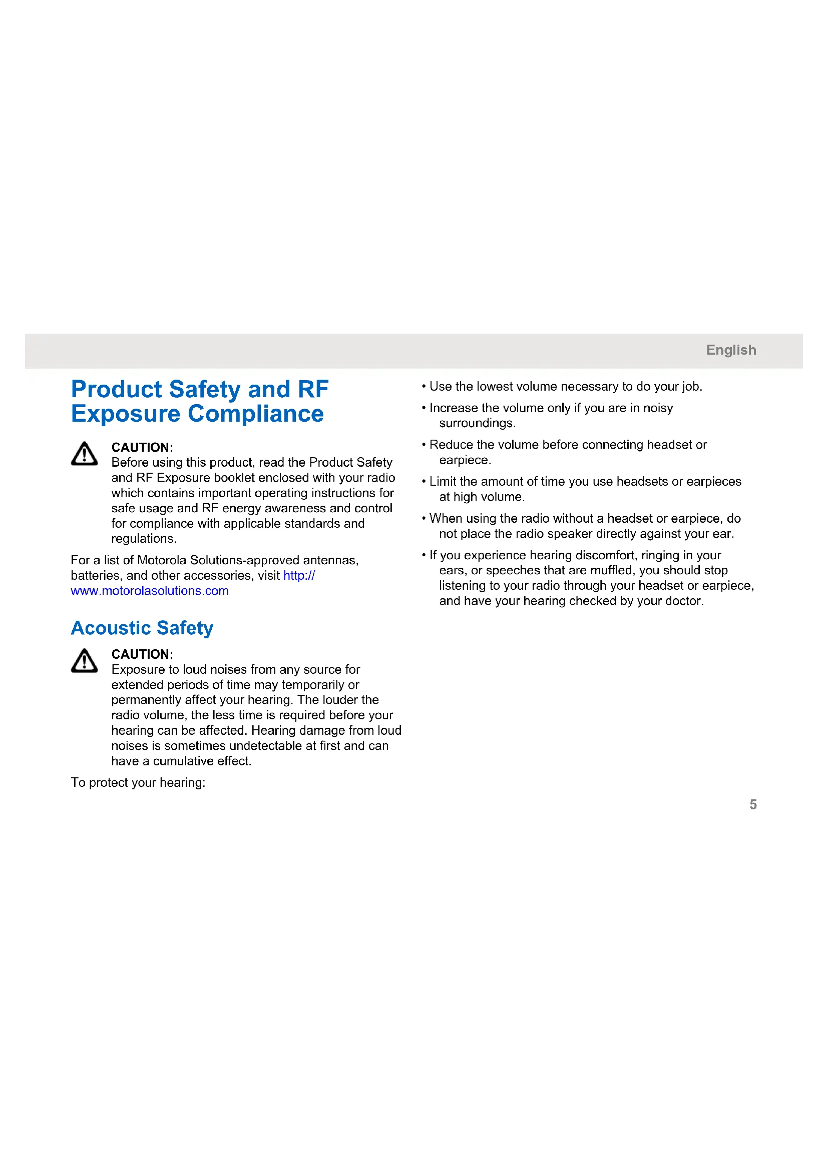
Product Safety and RF Exposure Compliance

CAUTION:
Before using this product, read the Product Safety and RF Exposure booklet enclosed with your radio which contains important operating instructions for safe usage and RF energy awareness and control for compliance with applicable standards and regulations.
For a list of Motorola Solutions-approved antennas, batteries, and other accessories, visit http://www.motorolasolutions.com
Acoustic Safety

CAUTION:
Exposure to loud noises from any source for extended periods of time may temporarily or permanently affect your hearing. The louder the radio volume, the less time is required before your hearing can be affected. Hearing damage from loud noises is sometimes undetectable at first and can have a cumulative effect.
To protect your hearing:
- Use the lowest volume necessary to do your job.
- Increase the volume only if you are in noisy surroundings.
- Reduce the volume before connecting headset or earpiece.
- Limit the amount of time you use headsets or earpieces at high volume.
- When using the radio without a headset or earpiece, do not place the radio speaker directly against your ear.
- If you experience hearing discomfort, ringing in your ears, or speeches that are muffled, you should stop listening to your radio through your headset or earpiece, and have your hearing checked by your doctor.
English
Introduction
This user guide covers the operation of your radios.
This radio is a product of Motorola Solutions' 90 years of experience as a world leader in the designing and manufacturing of communications equipment. This series provides cost-effective communications for businesses such as retail stores, restaurants, schools, construction sites, manufacturing, property and hotel management, and more. Motorola Solutions professional two-way radios are the perfect communications solution for all modern fast-paced industries.
Your dealer or system administrator may have customized your radio for your specific needs. Check with your dealer or system administrator for more information.

NOTICE:
Read this user guide carefully to ensure that you know how to properly operate the radio before use.
For product-related questions, contact: 1-800-448-6686 or visit us at: http://www.motorolasolutions.com/DTR600 and http://www.motorolasolutions.com/DTR700.
Package Contents
The following list encompasses the package content available:
Antenna
Radio
- Holster
Lithium-lon Battery
- Power Supply
- Quick Reference Guide
- Drop-in Tray Charger
Product Safety & RF Exposure Booklet
Notice to Users (FCC and Industry Canada)
The business two-way radios operate in the license-free 900 MHz ISM Band and are subject to the Rules and Regulations of the Federal Communications Commission (FCC).
This device complies with Part 15 of the FCC rules and Industry Canada's license-exempt RSS's per the following conditions:
- This device may not cause harmful interference.
- This device must accept any interference received, including interference that may cause undesired operation.
Changes or modifications made to this device, not expressly approved by Motorola Solutions, could void the authority of the user to operate this equipment.
To comply with FCC/IC requirements, transmitter adjustments should be made only by or under the supervision of a technically qualified person to perform transmitter maintenance and repairs. Replacement of any transmitter component such as crystal, semiconductor, and
other that are not authorized by the FCC/IC equipment authorization for this radio violates FCC/IC rules.

NOTICE:
Use of this radio outside the country where it was intended to be distributed is subject to government regulations and may be prohibited.
English
Batteries and Chargers Safety Information
This document contains important safety and operating instructions. Read these instructions carefully and save them for future reference. Before using the battery charger, read all the instructions and cautionary markings on:
the charger
the battery
- the radio attached with battery
- To reduce risk of injury, charge only the rechargeable Motorola Solutions-authorized batteries. Charging the other batteries may cause explosion, personal injury, and damage.
- Use of accessories not recommended by Motorola Solutions may result in fire, electric shock, or injury.
- To reduce damage to the electric plug and cord, pull by plug rather than the cord when disconnecting the charger.
An extension cord should not be used unless necessary. Use of an improper extension cord may result in fire and electric shock. If an extension cord must be used, make sure that the cord size is 18 AWG
for lengths up to 100 ft (30.48 m), and 16 AWG for lengths up to 150 ft (45.72 m).
- Do not operate the charger if it has been broken or damaged in any way. Take it to any qualified Motorola Solutions service representatives.
- Do not disassemble the charger; it is not repairable and replacement parts are not available. Disassembly of the charger may result in risk of electrical shock or fire.
- To reduce risk of electric shock, unplug the charger from the AC outlet before attempting any maintenance or cleaning.
Operational Safety Guidelines
- Turn off the radio while charging.
- The charger is not suitable for outdoor use. Use only in dry locations/conditions.
- Connect charger to an appropriately fused and wired supply of the correct voltage (as specified on the product only).
-
Disconnect charger from line voltage by removing main plug.
-
Connect the equipment to an outlet which is easy to access and near.
- For equipment using fuses, replacements must comply with the type and rating specified in the equipment instructions.
Maximum ambient temperature around the power supply equipment must not exceed 40^ (104^) - Power output from the power supply unit must not exceed the ratings stated on the product label located at the bottom of the charger.
- Make sure the cord is not stepped on, tripped over, subjected to water, damage or stress.
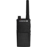
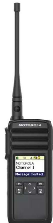
Radio Overview
This chapter explains the buttons and functions to control the radio.
Radio Parts
This chapter describes the buttons and functions of the radio.
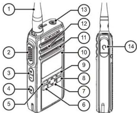
Figure 1: Radio Overview
Table 1: Radio Parts
| Label Item Description | |
| 1 Antenna Provides the needed RF amplification when transmitting or receiving. | |
| 2 Push-To-Talk (PTT) button | Press to transmit to other radios. |
| 3 Volume Up/ Down Control buttons | Press to adjust the volume level and to mute the radio. |
| 4 Programmable button | This button is field programmable by using the Customer Programming Software (CPS). |
| 5 P1 button Press to enter Message screen. | |
| 6 Menu/OK button Press to enter Menu and to confirm selection. | |
| 7 4-Way Navigation button | Press to toggle to the left/right/up/down of the selections available in the menu. |
| 8 Home/Back but- ton | Press to cancel and re- turn to a previous menu level; press and hold to return to Home screen. |
| 9 P2 button Press to view the con- tacts set in the radio. | |
| 10 Display A display that provides visual information about radio features. | |
| 11 Microphone Speak clearly into the mi- crophone when transmit- ting. | |
| 12 Speaker Outputs all tones and au- dio that are generated by the radio (for example, keypad tones and voice audio). | |
| 13 Power button Press to turn on and off your radio. | |
| 14 Audio Accessory Connector | Used to connect compat- ible audio accessories. |
Radio Specifications
The radio model is printed on the back of the radio with the following information.
Table 2: Radio Specifications
| Model Fre-quency Band | Trans-mit Power (Watts) | Number of Channels | Antenna |
| DTR600 ISM 900 MHz | 130 Remov- | able | |
| DTR700 ISM 900 MHz | 150 Remov- | able |
English
Status Indicators
This chapter explains the status indicators and audio tones used in the radio.
Icons
Your radio display shows radio status, text entries, and menu entries. The following are the icons that appear on the radio display.
Table 3: Display Icons
The following icons appear on the status bar at the top of the radio display.
| Battery These icons indicate the charge re- maining in the battery. The icon blinks when the battery is low. | |
| Mute Mode Mute Mode is enabled and speaker is muted. | |
| Ring Only Ringing mode is enabled. |
| Z | Scan Scan feature is enabled. |
| Silent Ring Silent ring mode is enabled. | |
| X | Tones Disable Tones are turned off. |
| Vibrate Vibrate mode is enabled. | |
| Vibrate and Ring Vibrate and Ring mode is enabled. | |
| Call Alert A call alert is received. | |
| Messages A text message is received. |
Table 4: Menu Icons
The following icons appear beside menu items that offer a choice between two options or as an indication that there is a sub-menu offering two options.
| Call Log Radio call log. | |
| Call Alert Message Read Call alert is read. | |
| Check box (Checked) Indicates that the option is selected. | |
| Check box (Empty) Indicates that the option is not select- ed. | |
| Individual or Group Message Read The text message has been read. |
| or Individual or Group Message Unread The text message has not been read. |
Table 5: Call Icons
The following icons appear on the display during a call. These icons also appear in the Contacts list to indicate the alias or ID type.
| Private Call Indicates a Private Call in progress. In the Contacts list, it indicates a sub-scriber alias (name) or ID (number). | |
| Group Call/All Call Indicates a Group Call or All Call in progress. In the Contacts list, it indicates a group alias (name) or ID (number). |
English
Table 6: Mini Notice Icons
The following icons appear momentarily on the display after an action to perform a task is taken.

Failed Transmission (Negative)
Failed action taken.

Successful Transmission (Positive)
Successful action taken.

Transmission in Progress (Transitional)
Transmitting. This is seen before indication for Successful Transmission or Failed Transmission.
| Contact Deleted Contact deleted from the contact list. | |
| + | Contact Added Contact added to the contact list. |
| → | Sender Info Indicates clone request sender infor- mation. |
Table 7: OTA Cloning
The following icons appear on the display during a call. These icons also appear in the Contacts list to indicate the alias or ID type.

OTA Cloning
Radio receives OTA contact cloning data.
Battery Features
The radio comes with standard Lithium-1on (Li-1on) batteries.
About Li-Ion Battery
The radio comes with a rechargeable Li-1on battery. This battery should be fully charged before initial use to ensure optimum capacity and performance.
Battery life is determined by several factors. The critical ones are overcharging of batteries and the average depth of discharge each cycle. Typically, the greater the
overcharge and the deeper the average discharge, the fewer cycles a battery will last. For example, a battery which is overcharged and discharged 100% for several times a day, lasts fewer cycles than a battery that overcharges less and is discharged to 50% per day. Battery with minimal overcharge and has an average of 25% discharge, lasts even longer.
Motorola Solutions batteries are designed specifically to be used with a Motorola Solutions charger and vice versa. Charging batteries with non-Motorola Solutions equipment may lead to battery damage and void the battery warranty. Whenever possible, maintain the battery temperature to 77^ (25^) (room temperature). Charging a cold battery (below 50^ [10^] ) may result in leakage of electrolyte and ultimate failure of the battery. Charging a hot battery (above 95^ [35^] ) results in reducing discharge capacity and affecting the performance of the radio. Motorola Solutions rapid-rate battery chargers contain a temperature-sensing circuit to ensure that batteries are charged within the temperature limits stated above.
Battery Recycling and Disposal
Li-ion rechargeable batteries can be recycled. However, recycling facilities may not be available in all areas. Under various U.S. state laws and the laws of several other
countries, batteries must be recycled and cannot be disposed of in landfills or incinerators. Contact your local waste management agency for specific requirements and information in your area. Motorola Solutions fully endorses and encourages the recycling of Li-Ion batteries.
In the U.S. and Canada, Motorola Solutions participates in the nationwide Call2Recycle program for battery collection and recycling. Many retailers and dealers participate in this program. For the location of the drop-off facility closest to you, access Call2Recycle's Internet web site at https:// www.call2recycle.org/ or call 1-800-8-BATTERY. This internet site and telephone number also provide other useful information concerning recycling options for consumers, businesses, and governmental agencies.
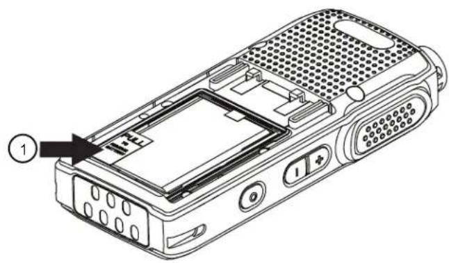
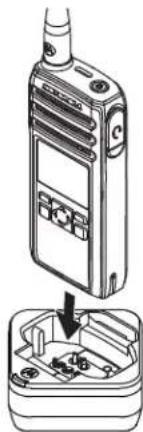
Installing the Li-Ion Battery
- Align the battery contacts with the contacts inside the battery compartment. Insert the contact side of the battery first. Gently push the battery into place and ensure the position of the battery flap is on top of the battery.
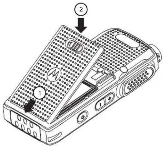
English
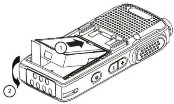
2 To attach battery cover, align it in place and slide the battery latch until it snaps into place.
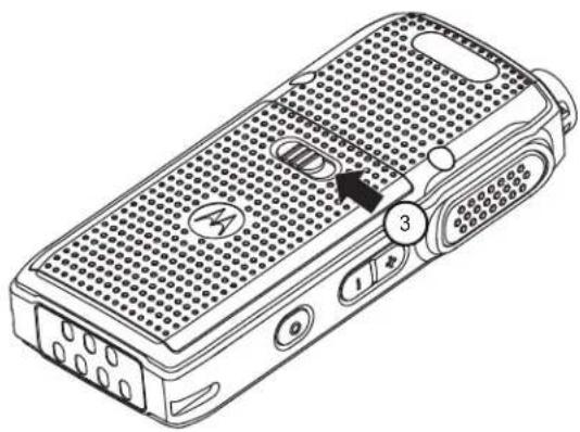
3 Slide battery latch into lock position.
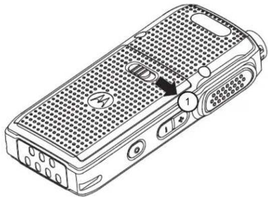
Removing the Li-Ion Battery
Ensure that the radio is turned off.
1 Move the battery latch to the unlock position.
2 Remove the battery cover by lifting the battery cover up.
English
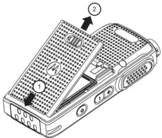
3 Pull the battery flap to remove the battery from the radio.
Holster
The following steps explain how to use a holster.
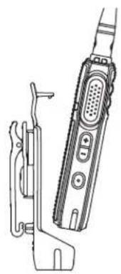
1 To insert the radio into the holster, press the radio against the back of the holster until the hook on the holster are inserted in the top recess.
2 To remove the radio from the holster, detach the hook of the holster from the top recess using the top tab and slide the radio out from the holster.
Power Supply and Drop-In Tray SUC
The radio is equipped with one power supply, and one single unit charger.
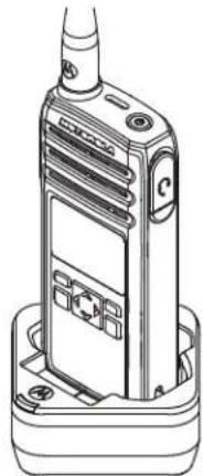
Figure 2: Charging with SUC
English
Battery Life
The battery lasts longer when Battery Save feature is set to on (enabled by default).
Table 8: Li-Ion Battery Life
| Battery Type Battery Save ON |
| Standard 16.5 hours |

NOTICE:
Battery save is enabled by default. Battery life is estimated based on 5% transmit/ 5% receive/ 90% standby standard duty cycle.
Battery Status Information
Battery status icon displays on the top left of the radio screen.
Table 9: Battery Status
| Battery Status Battery Level Battery Icon | ||
| High 71%-10 | 0% | |
| Medium 41%-70% | ||
| Low 11%-40% | ||
| Critical 0%-10% | ||
| Shutdown1 | 0% | |
Charging with the Drop-In Tray SUC
The radio comes with a standard power supply and a Single Unit Charger.

NOTICE:
Turn off the radio before charging and fully charge the battery before first use. It is best to charge at room temperature.
1 Place the SUC on a flat surface.
2 Insert the connector of the power supply into the port on the side of the SUC.
3 Plug the AC adapter into a power outlet.
4 Insert the radio into the SUC with the front of the radio facing the LED of the SUC. Ensure the radio is securely inserted all the way into the charger.

NOTICE:
For more information, see LED Indicator of Chargers on page 23 and Operational Safety Guidelines on page 8.
The charger LED flashes a few times to indicate the current battery capacity when the radio is inserted in the tray rails. The light on the charger is red to indicate that the battery is charging and turns green indicates that the battery is fully charged.
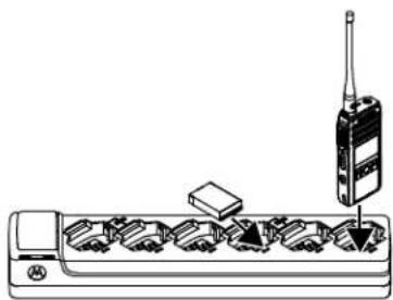
Charging a Stand-Alone Battery
Insert the battery into the charging pocket with the front of the battery facing the LED of the Single Unit Charger (SUC).
The charger LED flashes a few times to indicate the current battery capacity when the radio is inserted in the tray rails. The light on the charger is red to indicate that the battery is charging and turns green indicates the battery is fully charged.
For more information, see LED Indicator of Chargers on page 23.
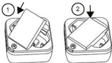
Figure 3: Charging a Stand-Alone Battery
Estimated Charging Time
The following table provides the estimated charging time of the battery. For more information, see Accessories on page 73.
Table 10: Estimated Charging Time
| Charging Solutions Estimated Charging Time | |
| Single-Unit Charger with 3 W Power Supply | 5 hours 15 minutes |
| Single-Unit Charger with 5 W Power Supply | 4 hours 15 minutes |
Charging Solutions Estimated Charging Time
Multi-Unit Charger 4 hours 15 minutes
Charging a Radio and Battery using a MUC
The Multi-Unit Charger (MUC) is an optional accessory and it has six charging pockets, which allows charging up to six radios or batteries. The batteries can be charged together with or without the radios or placed in the MUC separately.

NOTICE:
Turn off the radios before charging and it is best to charge at room temperature.
1 Place the MUC on a flat surface.
2 Insert the power cord plug into the dual pin connector at the bottom of the MUC.
3 Connect the power cord into an AC outlet.
4 Insert the radio or battery into the charging pocket with the front of the radio or battery facing the LED of the MUC.
The charger LED flashes a few times to indicate the current battery charge when the radio is inserted in the tray rails. The light on the charger is red to
indicate that the battery is charging and turns green indicates that the battery is fully charged.
LED Indicator of Chargers
The following table explains the LED Indicator shown on the chargers.
Table 11: Indicators
| Status LED Indicator Descrip- | tion | |
| Power On | Green for approxi- mately one second | - |
| Charging Steady red - | ||
| Charged Steady green - | ||
| Error2 | Fast-blinking red - | |
English
| Status LED Indicator Descrip- tion | ||
| Standby3 | Slowly blinking amber - | |
| Battery Level Status | Blinks red once Battery low | |
| Blinks amber twice Battery medium | ||
| Blinks green three Battery times high | ||
If there is no LED Indication:
-
Ensure that the radio with battery, or the battery alone, is inserted correctly.
-
Ensure that the power supply cable is securely plugged into the charger socket using the correct AC outlet and there is power to the outlet.
- Ensure that only Motorola Solutions authorized battery is used.
Getting Started
This section helps you to get familiar with the basic operation of the radio.
Turning the Radio On or Off
- To turn on the radio, press and hold the Power button until the radio vibrates and the display shows Motorola Logo.
- To turn off the radio, press and hold the Power button (~3 seconds) until the power down screen is shown and the power down tone is heard.
Adjusting Volume
There are 16 increments of volume. As the (+)/(-) buttons are pressed, you hear a beep at the current volume level. If device is receiving during volume interaction, received audio is heard at the new volume instead of beeps.
- Press the (+) button to increase the volume, or the (-) button to decrease the volume,
-
To mute, press, and hold the (-) button (~2 seconds) and the display shows Mute icon.
-
To unmute, press any volume button, the radio restores the previous volume.
- To maximize the volume, press and hold the (+) button (~2 seconds). The volume scrolls up fast to maximum volume. You hear the volume beeps increment as the volume increases.
NOTICE:
- Do not hold the radio too close to the ear when the volume is high or when adjusting the volume.
- When using radio with earpiece, make sure to adjust the radio volume to the lowest volume before putting on the earpiece. For more information, refer to Acoustic Safety on page 5. Use only Motorola Solutions approved accessories. For more information, refer to Accessories on page 73.
Browsing and Selecting Channels
To select a channel, press the Up or Down button on the home screen.
English

NOTICE:
Costumer Programming Software (CPS) limits the maximum number of characters for a Channel Name to 20 characters. However the color display width is limited by pixel size.
Radio Call Features
This chapter explains all radio call features available in this radio.
Push-To-Talk (PTT) Button
The PTT button is the primary button used to initiate voice transmissions.
To talk, press the PTT button. A short alert tone which is the Talk Permit Tone (TPT) sounds. Wait for the TPT tone to end before talking. Hold the radio vertically 1 in. to 2 in. (2.5cm to 5cm) from mouth when talking. Release the PTT to listen.
While a call is not in progress, the PTT button is used to make a new call (see Making Calls on page 35).
Talk Permit Tone (TPT)
Talk Permit Tone (TPT) is a quick distinctive double beep tone that sounds after you press the PTT button, indicating the channel is free to talk.
TPT is useful in ensuring orderly communications by preventing radios from transmitting over ongoing conversations.

NOTICE:
To ensure that your words are not cut off, always wait for the TPT before you start to speak.
Home Channel
The Home Channel feature returns the radio to a predefined channel, known as the home channel after a specified idle time (see Selecting Home Channel on page 44).
Channel
The current channel that you selected to use.
PROFILE ID
Profile ID Number
The default Profile ID number for all radios is 0000. All radios in your group have to use the same Profile ID number in order to communicate. You need to make sure self contact hopset is matching to the Profile ID hopset.
English
To change the group Profile ID number, refer to the Advanced Settings on page 43.
Setting the Non-Interference or Privacy Feature
This feature ensures improved private communications by configuring an appropriate PROFILE ID number.

IMPORTANT:
By default, the PROFILE ID number is "0000". Ensure that all your radios are configured with the same PROFILE ID number and is easy to remember.
The Profile ID feature is enabled through Customer Programming Software (CPS) configuration.
1 Press Menu/OK Advanced PROFILE ID.
2 Enter a four-digit radio PROFILE ID number.
Talk Range
Talk range is the distance or the communication range of radios. Key considerations that affect range are: signal type, antenna, and obstructions. You can communicate
with a radio or a group of radios with the same configuration.
Table 12: Talk Range
| Model Steel or Con-crete Industrial Buildings | Multi-Level Buildings |
| ISM 900 MHz Up to 350,000 ft2 | Up to 30 floors |
Programmable Button Options
The Programmable button comes pre-programmed with the Private Reply feature.
By using Customer Programming Software (CPS) or the Advanced Settings of your radio, you can also configure the Programmable button to allow other call features, such as Page All Available, Call All Available, Direct Call, and Mute. You can also configure the button to disable these options.
For more details on how to configure the Programmable Button, refer to Configuring the Programmable Button on page 44 or Customer Programming Software (CPS) on page 57.
Private Reply
This feature allows two people to instantly connect privately after a group transmission.
Push the Programmable button to capture the radio ID of the person currently talking to your group and right after the transmission is over, push the PTT button to talk privately to that person.
Starting a Private Reply
The Programmable button is set to Private Reply feature by default. This feature allows two people to instantly connect privately after a group transmission is over.

NOTICE:
There is a channel Hangtime after a Private transmission. By default, the Hangtime is set to 10 seconds.
1 To initiate a Private Reply, press the Programmable button during a group call.
The display shows Private Reply On.
2 After a group call, press PTT button to call privately.
The display shows Private Reply.
3 Wait for the Talk Permit Tone to end and speak.
Canceling Queues
To exit queue mode, long press the Programmable button.
A tone sounds. Your radio exits queue mode and returns to the home screen.
Direct Call
The Direct Call Feature allows a user to call another predetermined user that has been mapped into the radio Programmable button one-on-one privately (this feature needs to be pre-programmed via CPS*).Users also have the option to assign the Private Contact feature to any radio channel instead of the Programmable button.This allows the radio Programmable button to be available for other radio features (for example: Private Reply or Mute) and
English
Direct Call to be set up in a special channel. (You can set up different direct calls in different channels).

NOTICE:
To set up the Direct Call function for the first time in your radio you must use the CPS (Customer Programming Software) which is available for free download at http://www.motorolasolutions.com. Once in the CPS, you must read and upload the radio IDs (identified in CPS as "privates") into the CPS in order to enable Direct Call and assign direct calls to specific radios. For more information refer to CPS Basic Menu Instructions on page 57.
Making a Direct Call
1 Press the Programmable button.
The display shows Direct Call Queue message and that you are in queue.
2 To call, press the PTT button.
The distinctive Private Talk Permit Tone (TPT) is heard.
3 Wait for the Talk Permit Tone to end and speak.
Call All Available
The Call All Available feature is functional for devices with more than one channel.
Call All Available feature allows a communication with all available radio users at once in a temporary "super channel group", without having to change through each channel individually. Call All Available is a group call to all users available on different channels and users who are not currently tied up in an on-going radio conversation4.
A user who wants to respond to a Call All Available transmission should press the PTT button before talking.
If someone initiates a Call All Available transmission, all users engaged in the Call All Available will have their Programmable button disabled (no Private Reply or Direct Call are allowed during this period).
The radio times out a Call All Available communication after four seconds of inactivity. The time out prevents all users from being tied up indefinitely in an unnecessary group conversation. Call All Available option can be assigned either to the Programmable button or to an extra channel5.
Starting Call All Available
By default, the Programmable button is set to Private Reply feature.

NOTICE:
Programmble button must be pre-programmed to Call All Available using Advanced Settings or Customer Programming Software (CPS).
1 Press the Programmable button.
The display shows Call All Available On, indicating that you are in a queue.
2 When your radio is in a queue, press the PTT button.
The display shows Call All Available.
3 Wait for the Talk Permit Tone to end and speak.
Page All Available
The Page All Available feature is functional for devices with more than one channel.
Page All Available allows a communication with all available radio users at once without having to change through each channel individually. Page All Available is a one-way group voice announcement to all users on different channels who are not currently tied up in an ongoing radio conversation6.
A user who wants to respond to a Page All Available transmission can reply privately by pressing the Programmable button before talking). The Page All Available feature prevents users from getting tied up in an unwanted ongoing group conversation.
English
The page All Available Mode is terminated once the PTT button is released. Page All Available option can be assigned either to the Programmable button or to a channel7.
Starting Page All Available

NOTICE: Programmble button must be pre-programmed to Page All Available using Advanced Settings or Customer Programming Software (CPS).
1 To turn on the Page All Available feature, press the Programmable button.
The display shows Page All Available On, indicating that you are in queue.
2 Press the PTT button.
The display shows Page All Available.
3 Wait for the Talk Permit Tone (TPT) to end and speak.
Scan
This feature allows your radio to cycle through the programmed Public Groups scan list and the Private Groups that your radio is a member of, looking for voice activity.
Scan only works for the same hopset of the current channels. The radio unmutes to the group that is being scanned only when a call is initiated and not during a late entry.
Public Groups and Private Groups scan lists are configured and enabled through Customer Programming Software (CPS).

NOTICE: All Private Groups that your radio is a member are scanned. You cannot choose the groups to be scanned.
English
Enabling Scan
Press the Menu/OK Advanced Scan Menu/OK.
A tick indicates that Scan is enabled.
English
Contacts Management
This chapter explains the contacts management functions in your radio.
Contact List
This feature allows you to save contacts. Each entry corresponds to an alias or ID that you use to initiate a call.
Each entry, depending on context, associates with a different contact type: Private Contact, Private Group, and Public Group.
Each entry within Contacts displays the following information:
- Contact Alias
- Contact ID
- Hopset
Adding New Contacts
1 To add a new contact, press P2 New Contact.
2 Enter the new Radio ID.
The display shows a positive mini notice.
3 Select frequency Hopset.
The display shows a positive mini notice.
Contacts
This section explains the operations for receiving, responding, making, and ending calls from contact list.
There are three types of contacts, which are:
1 Private
2 Private Group
3 Public Group
Private Group is created using a unique Radio ID of each radio and added into a group of people. Only this group of people is unmute to the conversation.
Public Group is unmute to all if they are in the same channel and same Profile ID pin.
Making Calls
1 To call, press P2 Contact Alias/Contact ID PTT.
The display shows the call icon, call type, and the contact alias or contact ID.
2 Wait for the Talk Permit Tone to end and speak.

NOTICE:
If you receive a busy tone and your radio display shows Call Failed, the contact is either not available, busy, or no users are reachable within transmission range.
3 Release the PTT button to listen.
Ending Calls
To end a call, perform one of the following actions:
a Release the PTT button.
b Wait for the hang time to expire.
The Home Screen appears.
Call Log
Your radio keeps track of recent incoming and outgoing calls. Call log feature is used to view and manage recent calls.
You can perform the following actions in each of your call lists:
- Delete
- Store
View Details
Storing Call Log
1 To scroll through a list of menu items, press the Menu/OK button.
2 Perform one of the following actions:
- To store incoming call log, select Call Log → Incoming → Call 1 → Store → OK
- To store outgoing call log, select Call Log → Outgoing → Call 1 → Store → OK
A tick indicates that the call log is saved.
English

NOTICE:
Only Private Call can be stored. Do not use this method to store Group Call.
Radio Contacts Feature
These features are to allow radio user to alert their contacts and view messages.
Call Alert
Call Alert enables you to pre-alert a specific radio user to call you back.
Sending Call Alerts
1 Select Contact by pressing P2 button. Radio displays the contact list.
2 Select the required contact and press Menu/OK button.
3 Scroll to Call Alert and press Menu/OK button. If the Call Alert acknowledgment is received, the display shows a positive mini notice. If the Call Alert acknowledgment is not received, the display shows a negative mini notice.
The receiving radio vibrates and displays Data Receiving momentarily, followed by alert notice with the calling radio ID.
The receiving radio plays ringer tone periodically and shows alert notice until you clear the notice or the notice is overridden by other display.
Text Messages
This feature allows the user to view received text messages and send text messages to other radio users. The pre-defined Quick Texts are programmed using Customer Programming Software (CPS).
Sending Quick Text
1 Press P1 Quick texts Menu/OK.
2 Scroll to the desired Quick Text message and press the Menu/OK button. The radio displays a list of contacts in Contact List.
English
3 Scroll to the desired contact and press Menu/OK.
If the Quick Text is received, the display shows a positive mini notice, plays ringer tone that was configured, and the radio vibrates.
If the Quick Text acknowledgment is not received, the display shows a negative mini notice.
To read the unread messages, press Messages Inbox.
The display shows the received messages.
Receiving Messages
- To read the text message, press the Menu/OK button.
The display shows the message at the Home screen. After reading the message, radio changes the message status to read and clears the message icon from the home screen.
To read the text message at another time, press the Back button.
The radio return to home screen and the message status remains unread.
Radio Settings
This section describes the basic radio operations.
Adjusting Display Brightness
1 Press the Menu/OK Settings Display Brightness
2 Select the level of brightness by pressing the Left/Right button.
The level of the brightness is adjusted.
Setting Backlight Timer
If the backlight setting is set to enabled, backlight turns on and restarts the timeout timer upon any button presses except PTT and long press to on or off button.
1 Press the Menu/OK Settings Display Backlight Timer.
2 Scroll Up/Down to the required setting.
3 Press the Menu/OK button.
A tick indicates the current selected timer.
Setting Menu Timer
Menu timer is the timer for the time duration that the Menu is shown after the last action by user.
1 Press the Menu/OK Settings Display Menu Timer.
2 Scroll Up/Down to the required setting.
3 Press the Menu/OK button. A tick indicates the current selected timer.
Enabling All Tones
When All Tone is set to enabled, all the radio tones sounds including Talk Permit Tone (TPT).
1 Press the Menu/OK Settings Tones/Alerts All Tones.
English
2 Select All Tones by pressing the Menu/OK button. A tick indicates that All Tones is enabled.
Enabling Ringer Volume
This feature allows the user to set the loudness of the Ringer Tone that sound due to receiving of message or call alert.
1 Press the Menu/OK Settings Tones/Alerts Ring Volume
2 Adjust the volume by pressing the Left/Right button. The ringer tone plays to indicate the increase or reduction of the volume.
Enabling Vibrate
Vibrate feature allows the user to enable vibration upon radio response for incoming voice calls, call alert, or messages.
1 Scroll through a list of menu items by pressing the Menu/OK button.
2 To enable Vibrate, select the Settings Vibrate.
3 Press the Menu/OK button. A tick indicates that Vibrate is enabled.
Enabling Ringer Tone
You hear a ringer tone when the radio receives either a text message or call alert according to user selection.
1 Press the Menu/OK Settings Tones/Alerts Ringer Tone.
2 Scroll through the four Ringer Tones and select the Ringer Tone by pressing the Left/Right button.
Enabling Keypad Tone
Radio generates a tone when a button is pressed, except PTT and Power ON/OFF button.
1 Press the Menu/OK Settings Tones/Alerts Keypad Tone.
2 Press the Menu/OK button. A tick indicates that Keypad Tone is enabled.
Enabling Power Up Tone
Radio sounds a tone when radio powers up.
1 Press the Menu/OK Settings Tones/Alerts Power Up.
2 Press the Menu/OK button. A tick indicates that Power Up Tone is enabled.
Selecting Mic Gain for Radio
Radio mic gain refers to the audio gain of the radio internal microphone.
1 Press the Menu/OK Settings Mic Gain Radio.
2 Press Up/Down to the required setting.
3 Press the Menu/OK button. A tick indicates the current selected Mic Gain.
Selecting Mic Gain for Accessory
Radio mic gain refers to the audio gain of the radio accessory microphone.
1 Press the Menu/OK Settings Mic Gain Accessory.
2 Press Up/Down to the required setting.
English
3 Press the Menu/OK button.
A tick indicates the current selected Mic Gain.
Setting Languages
You can choose the language for text display in the radio.
1 Press the Menu/OK Settings Language.
2 Press Up/Down to the required setting.
3 Press the Menu/OK button.
A tick indicates the current selected language.
Configuring the Channel List
Configure channel list is a feature that allows you to choose which channel can be shown in the home screen channel selection.
1 Press the Menu/OK Settings Config CH List.
2 Press Up/Down to the required channel.
3 Press the Menu/OK button.
A blue bullet point indicates that the selected channel has been enabled.
Advanced Settings
The Advanced settings allow you to configure special settings in your radio without the need of programming cables or additional software.
PowerSave Mode
PowerSave Mode reduces radio power consumption.
PowerSave Mode can be configured in Customer Programming Software (CPS) or radio Menu. It disables the settings of the backlight and the vibration of the radio.
Enabling PowerSave Mode
1 Press the Menu/OK Advanced PowerSave.
2 Select Power Save Mode by pressing the Menu/OK button.
A tick indicates that PowerSave Mode is enabled.
Changing Profile ID Number
The Profile ID number improves the privacy of communication. The Profile ID feature is enabled through Customer Programming Software (CPS) configuration.
The following table refers to the backward compatibility naming with legacy DTR. Hopset in the new DTR is Channel in Legacy DTR. The last digit of Profile ID is tied to Hopset number.
The allowable Profile ID number is within 0000-9999. Changes in Profile ID number affects the hopset number.
Profile ID number setting is a sequence loop back of a number of available hopset.
Table 13: Backward Compatibility Naming with Legacy DTR
| Hopset Profile ID Num- ber | Channel (Lega- cy DTR) |
| 1 xxx0, xxx1 1 | |
| 2 xxx2 2 | |
| 3 xxx3 3 | |
| 4 xxx4 4 |
English
| Hopset Profile ID Num- ber | Channel (Lega- cy DTR) |
| 5 xxx5 5 | |
| 6 xxx6 6 | |
| 7 xxx7 7 | |
| 8 xxx8 8 | |
| 9 xxx9 9 | |
| 10 xx10 10 |
Configuring the Programmable Button
Programmable button allows you to assign a feature onto it using Customer Programming Software (CPS) or radio Menu.
1 Press the Menu/OK Advanced Programmable button.
2 To scroll through a list of feature to set for the Programmable button, press the Up/Down button.
3 Press the Menu/OK button.
A tick indicates the current selected feature for the Programmable button.
Selecting Home Channel
The purpose of the Home Channel feature is to return the radio to a predefined channel (home channel) after a specified idle time in the homescreen when radio is not on the Home Channel.
1 Press the Menu/OK Advanced Home Channel.
2 To scroll through a list of Home Channel, press the Up/Down button.
3 Select Home Channel by pressing the Menu/OK button.
A tick indicates the current selected Home Channel.
Clone Mode
You can clone radio profiles from a Source radio to a Target radio by using any one of these four methods:
Multi-Unit Charger (MUC- optional accessory)
- Two Single Unit Chargers (SUC) and a Radio-to-Radio cloning cable (optional accessory)
- Wireless PIN cloning
- Customer Software Programming (CPS)-(free software download)
Cloning with a MUC (Optional Accessory)
To clone radios using the Multi-Unit Charger, you must obtain at least two radios:
- A fully charged battery in each of the radios.
- a Source radio (radio from which the profiles are cloned or copied).
- a Target radio (radio to which the profiles are cloned from the source radio).
The Source radio has to be in Pocket 1 and 2, while the Target radio has to be in Pocket 4 and 5, matching in the MUCs pockets by pairs as follows:
-1 and 2
-4 and 5
MUC pockets numbers should be read from left to right with the Motorola Solutions logo facing front.
Paired Target radios and Source radios must be of the same band type in order for the cloning to run successfully.
When cloning, the MUC does not need to be plugged into a power source, but all radios require charged batteries.
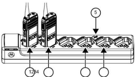
Figure 4: Multi-Unit Charger
| Label Item |
| 1 Pocket 1 |
| 2 Pocket 2 |
| 3 Pocket 4 |
| 4 Pocket 5 |
| 5 "CLONE" symbol |
1 Turn on the Target radio and place it into one of the MUC Target Pockets.
2 Power the Source radio by performing the following actions:
a Press the Menu/OK Advanced Cloning Radio Cloning
b Put the radio inside the MUC pocket.
c Press the Menu/OK button.
The display shows Cloning....
If successful:
The display shows Cloned Successfully.
If unsuccessful:
The display shows Cloning Failed.

NOTICE:
After completing the cloning process, user can replace the Slave Radio with another Slave Radio and by pressing the Menu/OK button on the Master radio to clone on second Slave Radio.
3 Exit the 'cloning' mode by long pressing the Home/ Back button.
4 If cloning fails, refer to What To Do If Cloning Fails on page 48.
When ordering the MUC, refer to P/N# PMPN4465.

NOTICE:
User should not remove the radios from the MUC when cloning is on-going.
Cloning Radio Using Two SUCs and a Radio-to- Radio Cloning Cable (Optional Accessory)
Before starting the cloning process, ensure that you have the following hardware:
- A Cloning Cable (P/N# HKKN4028_).
- A fully charged battery in each of the radios.
- Two Single-Unit Chargers (SUC) for radio cloning.
- Ensure that the radios are turned on.
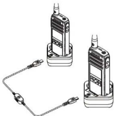
Figure 5: Radio to Radio Cloning
1 Plug one side of the cloning cable micro-USB connector to the first SUC and the other end to the second SUC.

NOTICE:
During the cloning process, no power is being applied to the SUC. The batteries are not charged. Only data communication is being established between the two radios.
2 Turn on the Target Radio and place it into one of the SUCs.
English
3 For the Source Radio, perform the following actions:
a Press the Menu/OK Advanced Cloning Radio Cloning
b Place the Source Radio in its SUC.
c Press the Menu/OK button.
The display shows Cloning...
If successful:
The display shows Cloned Successfully.
If unsuccessful:
The display shows Cloning Failed.
4 After completing the cloning process, exit the 'cloning' mode by long pressing the Home/Back button.
What To Do If Cloning Fails
In the event that the cloning fails, perform each of the following steps before attempting to start cloning process again:
1 Ensure that the batteries on both radios are fully charged and engaged properly on the radio.
2 Check the cloning cable connection on both SUCs.
3 Ensure that there is no debris in the charging tray or on the radio contacts and the radio contact is touching the SUC/MUC contact firmly.
4 Ensure that the Target radio is turned on.
5 Ensure that the Source radio is in cloning mode.
6 Ensure that the two radios are both from the same frequency band, and same region.
English

NOTICE:
This cloning cable is designed to operate only with compatible Motorola Solutions SUC.
When ordering Cloning Cable Kit, please refer to P/N# HKKN4028_. For more information about the accessories, see.
Cloning PROFILE ID Number Through Wireless
The PROFILE ID Number Wireless Cloning feature is useful when you want to clone the PROFILE ID Number for all the radios in your fleet but you do not want to clone particular radio settings that may be unique for each radio (like Programmable button configuration, Microphone Gain, Radio Name and others). It is also useful if you do not have a programming cable, or PC available to use with the Customer Programming Software (CPS) configuration.
The Profile ID feature is enabled through CPS configuration.
1 Power the Target Radio and perform the following actions:
a Press the Menu/OK Advanced Cloning Prof. ID Cloning.
b Press the Menu/OK button.
The display shows Profile Clone Mode On.
2 Power the Master Radio and perform the following actions:.
a Press the Menu/OK Advanced Cloning Prof. ID Cloning.
b Press the Menu/OK button.
The display shows Profile Clone Mode On.
c Press the Menu/OK button.
The display shows Profile ID Cloning...
If successful:
The display shows Cloned Successfully.
If unsuccessful:
The display shows Cloning Failed.
English

NOTICE:
- If target radio shows Cloning Failed using Wireless Cloning feature, try again with distance of at least 1 ft away from source radio.
Over The Air Contact Cloning
Over the Air (OTA) Contact Cloning feature allows you to add or delete contacts to or from another radio wirelessly without connecting the radios by cable.
You can clone over either private, private group, or public group while the targeted slave radio contact can be either private or private group. OTA contact cloning feature is enabled through Customer Programming Software (CPS) configuration.
Cloned contact replaces the contact in the slave radio if the existing contact has the same private ID, channel ID, or same name.
If a contact is mapped to a channel and Direct Call, removing the contact resets the channel to default channel ID and name.
Contact Cloning Remote Add
1 Press the Menu/OK Advanced Cloning Contact Cloning Remote Add. The radio displays the contact list to be added.
2 Do one of the followings:
- Scroll to select the contact and press Menu/OK.
- To clone all the contacts in the master radio, select All and press Menu/OK. Radio displays the Remote Send to screen.
3 Scroll to the target contact and press Menu/OK. Radio displays the Confirm Add? screen.
4 To confirm remote add, press Menu/OK. If cloning takes more than 10 minutes, radio displays Cloning takes min, OK?.
5 To continue, press Menu/OK. If successful, radio displays Cloned Successfully.
English
If unsuccessful, radio displays Cloning Failed followed by the list of contacts that failed cloning.
The receiving radio displays Data Receiving momentarily, followed by the contact to be cloned and the clone request sender information.
6 To retry cloning, select the private contact in the Cloned Failed screen and press Menu/OK If successful, radio displays Cloned Successfully.
Contact Cloning Remote Delete
1 Press the Menu/OK Advanced Cloning Contact Cloning Remote Delete. The radio displays the contact list to be deleted.
2 Scroll to select the contact and press Menu/OK. Radio displays the Remote Send to screen.
3 Scroll to the target contact and press Menu/OK. Radio displays the Confirm Delete? screen.
4 To confirm remote delete, press Menu/OK. If deleting takes more than 10 minutes, radio displays Cloning takes min, OK?
5 To continue, press Menu/OK. If successful, radio displays Cloned Successfully. If unsuccessful, radio displays Cloning Failed followed by the list of contacts that are not deleted. The receiving radio displays Data Receiving momentarily, followed by the contact to be cloned and the clone request sender information.
6 To retry deleting, select the failed contact in the Cloned Failed screen and press Menu/OK If successful, radio displays Cloned Successfully.
English
Manager Mode and Features
Manager mode allows the supervisor to use the radio to monitor and control the subordinate's radio.
The following features are available in the Manager mode radios:
- Remote Enable and Disable
Remote Monitor
This feature is enabled through Customer Programming Software (CPS) configuration. Once enabled, radio shows both the remote control features.
Remote Disable
Radios configured as Manager are able to disable a working radio from functioning.
1 Press the Menu/OK Advanced Manager Mode.
2 To disable the target radio, press Remote Disable Menu/OK
The radio displays the contact list.
3 Scroll to the required contact and press Menu/OK.
If successful, the Manager radio displays a positive mini notice.
If unsuccessful, the Manager radio displays a negative mini notice.
Receiving radio displays Data Receiving momentarily followed by power cycle, and then displays Radio Disabled.

NOTICE:
The remote disable fails if the followings happen:
- Target radio is out of range.
- Target radio is transmitting or receiving data or call.
- Target radio is disabled or is powered down.
- Manager radio records a wrong hopset of the target radio.
A disabled radio can only power up, off, or accept remote enable message.
Remote Enable
Radios configured as Manager allows a disabled radio to be enabled.
1 Press Menu/OK Advanced Manager Mode.
2 To enable the target radio, press Remote Enable Menu/OK.
The radio displays the contact list.
3 Scroll to the required contact and press Menu/OK.
If successful, the Manager radio displays a positive mini notice.
If unsuccessful, the Manager radio displays a negative mini notice.
Remote Monitor
Radios configured as Manager Mode are able to remotely monitor and listen to the environment of the other radio for 30 seconds provided the target radio is in the range.
1 Press the Menu/OK Advanced Manager Mode Remote Monitor.
2 Press the Menu/OK button.
The radio displays the remote monitor contact list.
3 Scroll to the required contact and press Menu/OK.
If successful, the Manager radio sounds a tone and the display shows a positive mini notice.
If unsuccessful, the Manager radio sounds a tone and the display shows a negative mini notice.
The receiving radio displays Remote Monitoring and make private call to the Manager radio.

NOTICE:
If the monitored radio is turned off while being monitored, remote monitor is terminated.
English
Rental Timer
The Rental Timer feature allows the radio rental company to set a permitted rental period to your radio and to disable the radio beyond the duration of specified time.
The radio can be programmed with a maximum rental period of 999 hours. The timer calculates the radio usage time and disables the radio when the usage time reaches the predetermined rental period. After the rental period expires, the radio ceases to function until the dealer resets the rental timer.
The radio displays the remaining rental duration in radio info screen if Rental Timer feature is enabled. Rental Timer feature can only be enabled or reset through Customer Programming Software (CPS) configuration.

NOTICE:
This feature is only applicable to DTR 600.
Rental Expiry Reminder
Rental Expiry Reminder feature provides reminders when the rental period is expiring.
This feature triggers the reminder hourly for the remaining eight hours before expiry.
6-8 hours before expiry
A tone sounds and the radio displays the remaining rental timer with green notice.
This reminder repeats every following hour.
2 hours before expiry
A tone sounds and the radio displays the remaining rental timer with red notice.
This reminder repeats the following hour.
Radio will power cycle and then displays Radio Disabled when the rental period expires. Radio is then disabled.
Resetting to Factory Defaults
- To reset your radios to the original factory defaults, power up using the Power button while pressing PTT, Volume (-) and Volume (+) buttons simultaneously.
The display shows Factory Reset.
Radio Factory Default Settings
Table 14: Radio Basic Feature Defaults
| Radio Basic Feature | Default |
| Number of channels | Default number of channels supported by radio model supported by the radio model |
| MIC Gain Medium | |
| Contacts All contacts will be deleted and re-store to factory default settings. | |
| Language As per region | |
Table 15: Advanced Settings Defaults
| Advanced Settings Default | |
| Radio PROFILE ID Num- ber | 0000 |
| Direct Call Off | |
| Home Channel Disabled | |
| Battery Save On | |
| PowerSave Off | |
| Programmable button Private Reply | |
| PROFILE ID Number lock On | |
Table 16: Radio Special Mode Defaults
| Radio Special Mode Default | |
| Enable restore Factory Default reset | On |
| Enable Cloning Mode On | |
| OTA Contact Cloning Mode Off | |
English

NOTICE:
For all other radio defaults, please refer to the Customer Programming Software (CPS).
Customer Programming Software (CPS)
To program or change a feature, a CPS must be installed on a computer.
The CPS allows programming features such as Direct Call, Private Groups, and Contacts. You are allowed to set up a password for your radio profile on your CPS for security purpose.
The CPS software is available for free at: http:// www.motorolasolutions.com/DTR600 and http:// www.motorolasolutions.com/DTR700.
Programming the Radio to CPS
1 To configure the radio using Customer Programming Software (CPS), place the radio into the Single Unit Charger (SUC).
2 Connect the CPS Programming Cable one side to the SUC and another to the computer.
3 Turn the switch on the CPS Programming Cable to the digital position.
CPS Basic Menu Instructions
1 Open the Customer Programming Software and click on the RADIO top tab.
2 Perform one of the following actions:
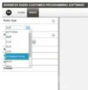
a Click on the READ tab to read the radio. 8
b If you want to open a new profile or an existing file, from the drop-down menu Radio Type, select DTR690/DTR790.
English
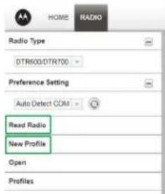
3 Perform one of the following actions:
a Click Read Radio.
The radio sounds a series of tones to indicate that reading is in progress and uploads your radio profile settings.
b To create customized profile based on the default profile, click New Profile.
4 Scroll down to see more feature options. Customize as necessary.
English
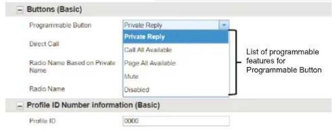
5 Modify the radio Programmable button feature by changing the default option.
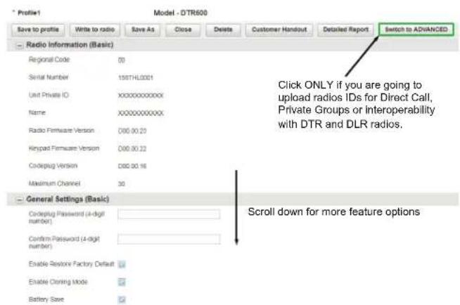
6 To enable the Direct Call feature in your Basic Menu options, perform the following actions:
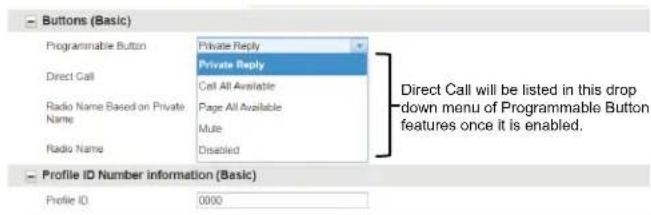
a Upload the radio(s) unique private identification (11 digit) number.
b Click on the Switch to ADVANCED button.
English
c On Privates (Advanced) tab, Click Add for CPS to upload the radio ID.
d Customize the radio ID name under the Name column. After a radio ID is uploaded, the CPS enables the Direct Call feature.
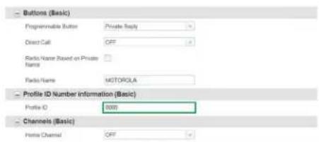
e After Direct Call is selected in Programmable button options, set the preferred contact to call for the Direct Call choice.
7 Set PROFILE ID number for any four-digit number different from "0000" to differentiate your radios in a radio fleet.
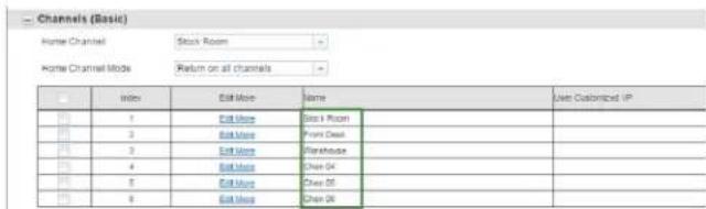
8 Assign the Home Channel by performing the following actions:
a To assign a specific channel as your Home Channel, select the channel using the drop-down menu under Home Channel. CPS enables the option to choose any channel you want as your designated Home Channel for the radio that you are programming9.
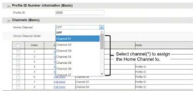

NOTICE: Home Channel is turned off by default.
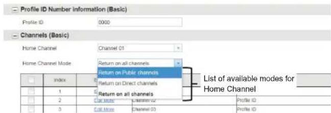
b After setting your Home Channel, select the mode using the drop-down menu under Home Channel Mode.
9 Customize the name of your channel (alias) in the Name column.
10 After changing all the settings, program your radio by clicking Write to radio button.
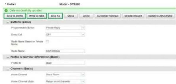
CPS displays a window confirming the programming of your radio is successful.

NOTICE:
Save your profile at any time to use the same settings when programming other radios by clicking on Save to profile button. This saves the profile to the current default path on your computer. To specify a different path to save the profile, click the Save As button.
English
Troubleshooting
The following table explains the ways to troubleshoot if the symptom occurred.
Symptoms and Solutions
If... Then...
No Power Recharge or replace the Li-Ion battery.
Extreme operating temperatures may affect battery life.
Refer to About Li-Ion Battery on page 14.
Unable to read the radio (using the CPS)
Ensure that one side of the programming cable is connected to the radio and the other side of the programming cable is connected to the USB port.
Verify that the switch on the programming cable is set at "Digital"
If... Then...
| position or “Flash” position in older version programming cable. Ensure that the radio is positioned correctly inside the Single Unit Charger (radio making proper contact with the charger). | |
| Radio generates continuous tone when PTT is pressed | Radio does not transmit when it is receiving as receive mode has higher priority than transmit mode. Press the PTT button again when receive mode ends. |
| Radio does not transmit when pressing the radio PTT button | If there are other users who are using the channel, the radio does not transmit. Try again after verifying that nobody else is talking. By default, the radio PTT button is disabled on the radio whenever there is an earpiece connected to it. Make sure to use the earpiece in-line PTT button to transmit instead. |
| If... Then... | |
| Hearing conversation from other users that are not within your channel | If you hear conversations from other users that do not belong to your radio fleet, it means that your radios are set up with the same Profile ID as your neighbors. |
| Likely both of you have the radios set to the default PROFILE ID Number "0000". | |
| Customize your PROFILE ID with a 4-digit number for all your radios. | |
| Hearing crack- ing noises when nobody is talking | Sometimes users inadvertently press the radio PTT button against objects while wearing the radio on their belts or pockets. When they do this, the radio starts transmitting and holding the channel therefore generating strange noises. Using earpieces reduce the likelihood of this happening. |
| Ensure that everybody in your team is aware of proper operation of the radios. | |
| If... Then... | |
| Audio quality not good enough | Radio settings might not be matching up correctly. Double check to ensure that the radio settings are identical in all radios. Go into Advanced Settings and adjust the microphone sensitivity gain (MIC Gain). For more information, refer to Advanced Settings on page 43. |
| Audio sounds garbled/robotic | Digital technology gives you the advantage to experience clear audio up to the edge of the range. However, when maximum transmission range has been reached, audio may sound garbled just before the transmission is lost completely. To avoid this problem, ensure that you are within transmission range. |
| Transmit audio is low | Hold the radio vertically 1 inch to 2 inches from mouth when talking. |
English
| If... Then... | |
| For accessory, hold the accessory microphone 2 inches to 3 inches from mouth when talking. | |
| While talking on the radio, a loud tone interrupted the conversa-tion | When talking on the radio, make sure not to release the PTT button at any moment. Whether you are using the PTT button on the radio or using an in-line PTT in an earpiece accessory, always press the PTT button firmly until the transmission is finished.Releasing the PTT button while transmitting and trying to immediately press the PTT button again causes the radio to give you a loud denial tone.If you press the PTT button to transmit and a busy tone is received instead of a TPT, this means the channel is either not available, busy or there are no users reachable within transmission range. |
| If... Then... | |
| Limited talk range | Steel and/or concrete structures, heavy foliage, buildings, or vehicles decrease range. Check for clear line of sight to improve transmission. Wearing radio close to body such as in a pocket or on a belt decreases range. Change location of radio. To increase range and coverage, you can reduce obstructions. Radios provide greater coverage in industrial and commercial buildings |
| Radio echo feedback | All radios produce strong voice/ audio feedback if they are too close to each other and their volume is set too high. Lower the volume in your radio. Using earpieces can also help reduce audio feedback if radios are too close. |
PTT is pressed, transmitting radio shows Call Failed at close
| If... Then... | |
| distance with receiving radio | |
| Voice not transmitted or received | Ensure that the PTT button is completely pressed when transmitting. Confirm that the radios have the same settings and PROFILE ID. Ensure that radios are on the same channel. Ensure that you hear the Talk Permit Tone before talking. Speaking before hearing the tone, results in the first few words of the transmission being cut out. Recharge, replace and/or reposition the batteries. See About Li-lon Battery on page 14. Obstructions and operating indoors, or in vehicles, may create interferences. Change locations. |
| Heavy static or interference | Radios are too close; they must be at least five feet apart. |
| If... Then... | |
| Radios are too far apart or obsta-cles are interfering with transmis-sion. | |
| Low batteries Recharge or replace Li-Ion battery. | |
| Extreme operating temperatures af-fect battery life. | |
| See About Li-Ion Battery on page 14. | |
| Low battery in-dicator is blink-ing although new batteries are inserted | Refer to Installing Li-Ion Batterries and About Li-Ion Battery on page 14. |
| Battery does not charge although it has been placed in the drop-in charger for a while | Verify that the drop-in tray charger is properly connected and corre-sponds with a compatible power supply. |
| Refer to Charging with the Drop-In Tray SUC on page 20 and Charging A Stand-Alone Battery. | |
English
| If... Then... | Check the charger LEDs indicators to see if the battery has a problem. |
Contact Cloning Failures
This section describes the contact cloning failure scenarios and ways to troubleshoot.
| Cloning scenarios Actions | |
| The slave radio contact list is full. | Clean up the contact list and remove the unwanted contacts. |
| The slave radio is powered down. | Ensure the radio in ON. |
| The slave radio is out of range. | Ensure the radio is in the range. |
| If the Private contact or Private Group contact ID is not 11 digit. | Ensure the contact ID is 11 digit. |
| The slave radio Profile ID Number (PIN) is 0000 and | Ensure the slave radio PIN is not 0000 and the |
| Cloning scenarios Actions | |
| contact to be cloned or deleted is within Public Group 1-20. | contact is not within Pub-lic Group 1-20. |
| The slave radio PIN is locked and the contact to be cloned or deleted hop-set is different from the slave radio. | Ensure the radio PIN is not locked or same hop-set as the slave radio. Ensure the PIN matches Master radio. |
| If All is selected in the Remote Add screen, the slave radio and Master radio password does not match. | Ensure the password matches or the slave ra-dio does not have pass-WORD. |
| Slave radio is receiving or transmitting calls. | Perform clone after slave radio is done with receiv- ing or transmitting. |
| Home Group and Group Only contacts are empty in the slave radio. | Enable legacy DTR Pri- vate Settings through Customer Programming Software (CPS). Radio stores the Home Group and Group Only con-tacts. |
| The legacy DTR Private setting cannot be enabled. | Ensure the radio PIN is not 0000 and the Profile ID Number Lock is unchecked. |
| If contact is a member of six Private Groups, the cloned contact is missed out from the slave radio Private Groups. | No action is required. Legacy DTR only supports up to 5 Private Groups per contact. |
| Legacy DTR Ringer Tone resets after OTA Contact Cloning from new DTR. | No action is required. The new DTR radio ring-er tone is not assigned based on contacts. |
| Legacy DTR Private Scroll List resets after OTA Contact Cloning from new DTR. | No action is required. The new DTR radios do not have Private scroll list. Hence, Private scroll list is not cloned to the slave radio. |
| All cloned contacts from new DTR are displayed in legacy DTR radio scroll list. | No action is required. The new DTR radio is a |
| Cloning scenarios Actions | |
| channel based radio that does not use scroll list. | |
| Public Group 1-20 is not being cloned. | Public Group 1-20 is not cloned if Clone All is selected or if Master radio PIN is 0000. |
Use and Care
This chapter explains the maintenance of the radio.
| Do not immerse in water | Use a soft damp cloth to clean the exterior |
| Do not use alcohol or cleaning solutions | Do not place more than seven turned on radios, too close to each other in a container |
| If the radio is submerged in water, | |
| Turn the radio off and remove the battery | Dry with soft cloth |
| Do not use the radio until it is completely dry | - |
Motorola Solutions Limited Warranty for the United States and Canada
Warranty
Subject to the exclusions contained below, Motorola Solutions, Inc. warrants its telephones, pagers, and consumer and business two way radios (excluding commercial, government or industrial radios) that operate via Family Radio Service or General Mobile Radio Service, Motorola Solutions-branded or certified accessories sold for use with these Products ("Accessories") and Motorola software contained on CD-ROMs or other tangible media and sold for use with these Products ("Software") to be free from defects in materials and workmanship under normal consumer usage for the period(s) outlined below.
This limited warranty is a consumer's exclusive remedy, and applies as follows to new Motorola Products, Accessories and Software purchased by consumers in the United States, which are accompanied by this written warranty.
Products and Accessories
The table shows the length of coverage of products and accessories.
Table 17: Products and Accessories
| Products Covered Length of Coverage | |
| Products and accessories as defined above, unless otherwise provided for below | One (1) year from the date of purchase by the first purchaser of the product unless otherwise provided for below. |
| Decorative accessories and cases. Decorative covers, bezels, Phone-Wrap™ covers and cases | Limited lifetime warranty for the lifetime of owner-ship by the first purchaser of the product. |
| Business two-way radio accessories | One (1) year from the date of purchase by the first purchaser of the product. |
| Products and accessories that are repaired or replaced | The balance of the original warranty or for 90 days from the date re- |
| turned to the consumer, whichever is longer. | |
| Two-way radio Two (2) years from the date of purchase by the first purchaser of the product. | |
Exclusions
Normal Wear and Tear
Periodic maintenance, repair and replacement of parts due to normal wear and tear are excluded from coverage.
Batteries
Only batteries whose fully charged capacity falls below 80% of their rated capacity and batteries that leak are covered by this limited warranty.
Abuse and Misuse
Defects or damage that result from:
-
improper operation, storage, misuse or abuse, accident or neglect, such as physical damage (cracks, scratches, etc.) to the surface of the product resulting from misuse
-
contact with liquid, water, rain, extreme humidity or heavy perspiration, sand, dirt or the like, extreme heat, or food
- use of the Products or Accessories for commercial purposes or subjecting the Product or Accessory to abnormal usage or conditions
- other acts which are not the fault of Motorola Solutions, are excluded from coverage.
Use of Non-Motorola Solutions Products and Accessories
Defects or damage that result from the use of NonMotorola Solutions branded or certified Products, Accessories, Software or other peripheral equipment are excluded from coverage.
Unauthorized Service or Modification
Defects or damages resulting from service, testing, adjustment, installation, maintenance, alteration, or modification in any way by someone other than Motorola Solutions, or its authorized service centers, are excluded from coverage.
Altered Products
Products or Accessories with:
-
serial numbers or date tags that have been removed, altered or obliterated
-
broken seals or that show evidence of tampering
- mismatched board serial numbers
- nonconforming or non-Motorola Solutions housings, or parts, are excluded from coverage
Communication Services
Defects, damages, or the failure of Products, Accessories or Software due to any communication service or signal you may subscribe to or use with the Products Accessories or Software is excluded from coverage.
Software
Table 18: Software Warranty Table
| Products Covered Length of Coverage | |
| Software | 90 days from the date of purchase. |
| Applies only to physical defects of the media that embodies the copy of the software (for example CDROM, or floppy disk). | |
Exclusions
Software Embodied in Physical Media
The warranty does not cover that the software will meet your requirements or will work in combination with any hardware or software applications provided by third parties, that the operation of the software products will be uninterrupted or error free, or that all defects in the software products will be corrected.
Software not Embodied in Physical Media
Software that is not embodied in physical media (for example, software downloaded from the internet), is provided "as is" and without warranty.
Warranty Coverage
This warranty extends only to the first consumer purchaser, and is not transferable.
How to Obtain Warranty Service or Other Information
Contact your Motorola Solutions point of purchase.
English
Patent Notice
This product is covered by one or more of the following United States patents.
5896277 5894292 5864752 5699006 5742484 D408396
D399821 D387758 D389158 5894592 5893027 5789098
5734975 5861850 D395882 D383745 D389827 D389139
5929825 5926514 5953640 6071640 D413022 D416252
D416893 D433001
Export Law Assurances
This product is controlled under the export regulations of the United States of America. The Government of the United States of America may restrict the exportation or re-exportation of this product to certain destinations.
For further information, contact the U.S. Department of Commerce.
For questions or comments related to this product, please contact Motorola Solutions 1-800-448-6686 or visit: http:// www.motorolasolutions/DTR600 and http:// www.motorolasolutions/DTR700.
Accessories
The following tables are the accessories list.
Table 19: Antenna
| Part No. Description |
| PMAF4024_Whip Antenna 900-928 MHz |
| PMAF4025_Stubby Antenna 900-928 MHz |
Table 20: Audio Accessories
| Part No. Description |
| HKLN4599_Earpiece with PTT, Mic, Slim Plug |
| HKLN4601_Surveillance Earpiece with PTT, Slim Plug |
| HKLN4604_Swivel Earpiece with PTT, Slim Plug |
| HKLN4608_Transparent Acoustic Tube Replacement Part |
Table 21: Battery
| Part No. Description |
| PMNN4578_Li-Ion Battery 2500 mAh |
Table 22: Cables
| Part No. Description |
| HKKN4027_Business Radio CPS Cable Kit |
| HKKN4028_Business Radio Cloning Cable Kit |
Table 23:Chargers
| Part No. Description |
| PMPN4469_DTR Single-Unit Charger (SUC), 3 W Power Supply, North America |
| PMPN4465_DTR 6-Pocket Multi-Unit Charger (MUC), North America |
Table 24: Power Supplies
| Part No. Description |
| PS000228A01_3 W Power Supply, Micro-usb |
English
Part No. Description
PS000227A11_5 W Power Supply, Micro-usb
Table 25: Carry Accessories
Part No. Description
PMLN7939_DTR Swivel Clip Holster Kit
Notes
Français (Canada)
Table des matieres
Portee de communication. 31
Options du bouton programmable 32
Réponse privée. 32
MOTOROLA, MOTO, MOTOROLA SOLUTIONS and the Stylized M Logo are trademarks or registered trademarks of Motorola Trademark Holdings, LLC and are used under license. All other trademarks are the property of their respective owners. © 2018 and 2019 Motorola Solutions, Inc. All rights reserved.