
JPDA - Intercom Aiphone - Free user manual and instructions
Find the device manual for free JPDA Aiphone in PDF.

User questions about JPDA Aiphone
0 question about this device. Answer the ones you know or ask your own.
Ask a new question about this device
Download the instructions for your Intercom in PDF format for free! Find your manual JPDA - Aiphone and take your electronic device back in hand. On this page are published all the documents necessary for the use of your device. JPDA by Aiphone.
USER MANUAL JPDA Aiphone
General Prohibitions

Prohibition to Dismantle the Unit

Prohibition on Subjecting the Unit to Water

General Precautions

WARNING
Negligence could result in death or serious injury.
- Do not dismantle or alter the unit. Fire or electric shock could result.
- Existing wiring such as chime wiring, etc. may contain high voltage AC electricity. Damage to the unit or electric shock could result. Wiring and installation should be done by a qualified technician.
- This unit is not an explosion-proof unit. Do not install or use the unit in locations that are filled with flammable gas such as oxygen rooms. Fire or an explosion could result.

CAUTION
Negligence could result in injury to people or damage to property.
- Before turning on power, make sure wires are not crossed or shorted. If not, fire or electric shock could result.
- Do not install or make any wire terminations while power supply is plugged in. It can cause electrical shock or damage to the unit.
GENERAL PRECAUTIONS
- The door station is weather resistant, but do not spray high pressure water on door station directly. Unit trouble could result.
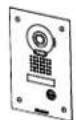
PACKAGE CONTENTS
Verify that the following parts are included.
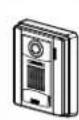
JP-DA
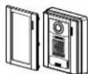
Front panel
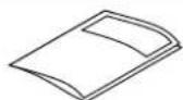
on manual
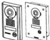
JP-DV
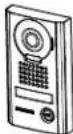
The unit
Special screwdriver Transparent nameplate (x2) Installation manual
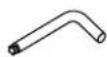
JP-DVF
The unit
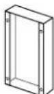
Flush mount back box

Special screw (x4)

Hexagonal wrench
Transparent nameplate (x2) Installation manual
INSTALLATION
Mounting locations
"Do not install video door station in any of the following locations where lighting or the ambient environment could impact the display on the video monitor due to the characteristics of the door station's camera."

Locations subject to direct sunlight
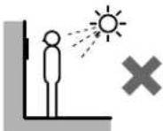

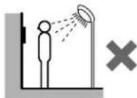
Under street lights or door lights
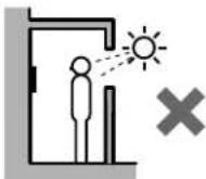
C Other locations subject to strong lighting or backlighting conditions
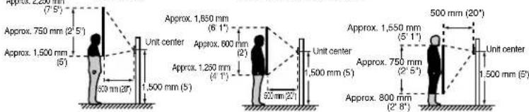
Mounting positions and image view area

Wide picture
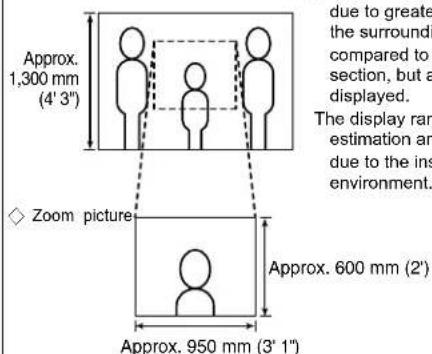
Objects appear smaller due to greater distortion in the surrounding sections compared to the central section, but a wider area is displayed.
The display range is a rough estimation and may change due to the installation environment.
The zoom position can be changed. (Refer to the master station's operation manual.) The factory setting is "Center" for Zoom mode.
Wide picture

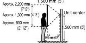
Mounting position

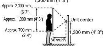
Mounting position
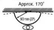
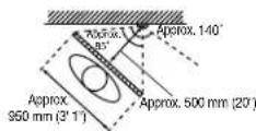
An area over a range of approx. 170^ in a 500 mm radius from the camera displays. (The display range is a rough estimation and may change due to the installation environment.)
Zoom picture(when mounting position is 1,500 mm (5'))

Zoom
Zoom

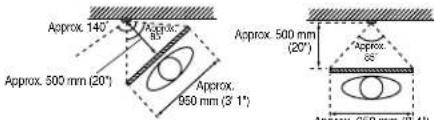
Zoom
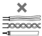
Cable
- Use PE (polyethylene)-insulated PVC jacket cable.
Parallel or jacketed 2-conductor, mid-capacitance, non-shielded cable is recommended. - Never use individual conductors, twisted pair cable, or coaxial cable.


JP-4MED
JPW-BA
Wiring distance
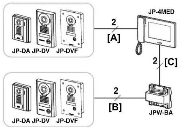
| Wire diameter | |||||
| Ø0.65 mm(22 AWG) | Ø0.8 mm(20 AWG) | Ø1.0 mm(18 AWG) | Ø1.2 mm(16 AWG) | ||
| [A] | Door station - masterstation | 50 m(165') | 100 m(330') | 100 m(330') | 100 m(330') |
| [B] | Door station - longdistance adaptor | 100 m(330') | 150 m(490') | 200 m(650') | 200 m(650') |
| [C] | Long distanceadaptor - masterstation | 50 m(165') | 75 m(245') | 100 m(330') | 100 m(330') |
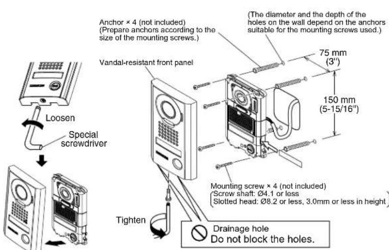
MOUNTING
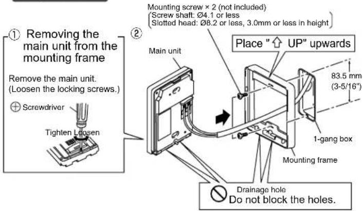
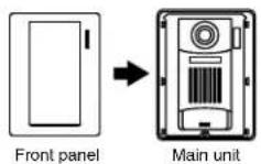
JP-DA
③ Mount the main unit on the mounting frame, and fit the front panel on.
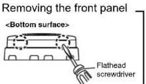
Pry off the front panel with a fl athead screwdriver.
JP-DV
* Remove protective fi lm from camera before use.
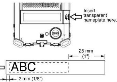
Using the transparent nameplates
Inserting the transparent nameplates
① Remove the vandal-resistant front panel.
Peel off the protective seals on the plate (both sides).
Fill in the name of the resident on the transparent nameplate. Be sure to leave 25mm (1") of white space on the right end to account for insertion.
④ Insert the filled-in transparent nameplate at the specified insertion opening (indicated with in diagram) as below.
JP-DVF
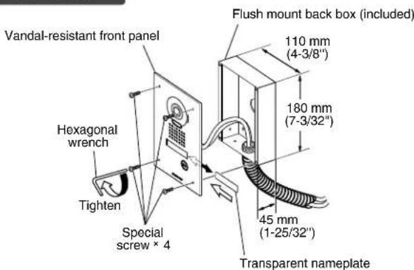
* Remove protective fi lm from camera before use.
Using the transparent nameplates
Inserting the transparent nameplates
③ Remove the vandal-resistant front panel from the flush mount back box.
② Peel off the protective seals on the plate (both sides).
3 Fill in the name of the resident on the transparent nameplate. Be sure to leave 25mm (1") of white space on the right end to account for insertion.
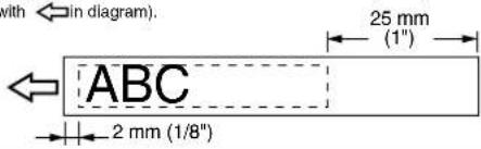
Insert the filled-in transparent nameplate at the specified insertion opening on the rear side of the vandal-resistant front panel (indicated with In diagram). 25 mm
WIRING
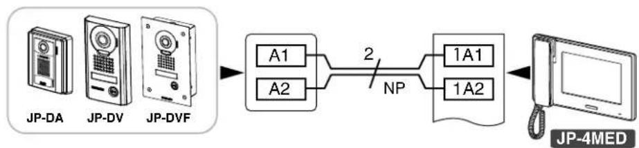
NP: Non-polarized
TECHNICAL PRECAUTIONS
-
Door station is weather resistant. However, do not spray high pressure water on door station directly. Unit trouble could result.
-
Cleaning:
-
Clean units with a soft cloth and gentle cleaner. Do not spray cleaner directly on unit. Do not use an abrasive cleanser or cloth.
-
Wipe away dirt from the lens softly with a soft cloth. Observe the following points for lens care.
-
Take care not to scratch the lens.
- Do not use organic solvents other than isopropyl alcohol (IPA) and methanol.
- Do not use thinner, benzene, etc. It may cause damage or discoloration to the surface of the unit.
SPECIFICATIONS
| Power supply Supplied from master station | ||
| Operating temperature - 10 - 60°C (+14°F) | ||
| Camera unit Complementary metal oxide semiconductor (CMOS) | ||
| Scanning lines 525 lines | ||
| Minimum subject illumination 5 Lux at 50 | cm (1'6") distance | |
| Dimensions JP-DA 129 (H) x 97 (W) x 30 | 0.5 (D) (mm) 5-1/8 (H) x 3-7/8 (W) x 1-3/16 (D) (inches) | |
| JP-DV 173 (H) x 98 (W) | x 27.1 (D) (mm) 6-13/16 (H) x 3-7/8 (W) x 1-1/16 (D) (inches) | |
| JP-DVF | 209 (H) x 135 (W) x exposed area 5.6 (D) (mm) 8-1/4 (H) x 5-5/16 (W) x 7/32 (D) (inches) | |
| Flush mount back box (JP-DVF) | 180 (H) x 110 (W) x 45 (D) (mm) 7-3/32 (H) x 4-3/8 (W) x 1-25/32 (D) (inches) | |
| Mass | JP-DA Approx. 170 g (0.37 lbs.) | |
| JP-DV Approx. 650 g (1.43 lbs.) | ||
| JP-DVF | Approx. 570 g (1.26 lbs.) | |
| Flush mount back box (JP-DVF) | Approx. 450 g (1.0 lbs.) | |
PRECAUTIONS
VOORZORGSGMAATREGELEN

Algemeen verbod

Aiphone warrants its products to be free from defects of material and workmanship under normal use and service for a period of two years after delivery to the ultimate user and will repair free of charge or replace at no charge, should it become defective upon which examination shall disclose to be defective and under warranty. Aiphone reserves unto itself the sole right to make the final decision whether there is a defect in materials and/ or workmanship; and whether or not the product is within the warranty. This warranty shall not apply to any Aiphone product which has been subject to misuse, neglect, accident, power surge, or to use in violation of instructions furnished, nor extended to units which have been repaired or altered outside of the factory. This warranty does not cover batteries or damage caused by batteries used in connection with the unit. This warranty covers bench repairs only, and any repairs must be made at the shop or place designated in writing by Aiphone. This warranty is limited to the standard specifications listed in the operation manual. This warranty does not cover any supplementary function of a third party product that is added by users or suppliers. Please note that any damage or other issues caused by failure of function or interconnection with Aiphone products is also not covered by this warranty. Aiphone will not be responsible for any costs incurred involving on site service calls. Aiphone will not provide compensation for any loss or damage incurred by the breakdown or malfunction of its products during use, or for any consequent inconvenience or losses that may result.
The object area of is the EU.
GARANTIE
Français
This device complies with Part 15 of the FCC Rules. Operation is subject to the following two conditions: (1) this device may not cause harmful interference, and (2) this device must accept any interference received, including interference that may cause undesired operation. This equipment has been tested and found to comply with the limits for a Class B digital device, pursuant to Part 15 of the FCC Rules. These limits are designed to provide reasonable protection against harmful interference in a residential installation. This equipment generates, uses, and can radiate radio frequency energy, and if not installed and used in accordance with the instructions, may cause harmful interference to radio communications. However, there is no guarantee that interference will not occur in a particular installation. If this equipment does cause harmful interference to radio or television reception, which can be determined by turning the equipment off and on, the user is encouraged to try to correct the interference by one or more of the following measures:
Reorient or relocate the receiving antenna
- Connect the equipment to an outlet on a circuit different from that to which the receiver is connected. Increase the separation between the equipment and receiver.
- Consult the dealer or an experienced radio/TV technician for help.
AIPHONE® Providing Peace of Mind http://www.iphone.net/
Issue Date: Oct. 2014
FK2096 A P1014 AZ 56125