L300KMG - Fan BROAN - Free user manual and instructions
Find the device manual for free L300KMG BROAN in PDF.

| Product Type | Ceiling/Wall Fan |
| Brand | Broan |
| Model | L300KMG |
| Power Supply | 120 VAC, 60 Hz |
| Housing Dimensions | Approximately 31.8 cm width, height adjustable from 3.8 to 6.4 cm |
| Duct Diameter | 8 in (20.3 cm) |
| Discharge | Horizontal or vertical (convertible) |
| Recommended Use | Continuous general ventilation |
| Control | On/off switch or solid state speed control |
| Grille Cleaning | Vacuum or soft cloth with mild soap |
| Blower Cleaning | Disassemble blower, clean with vacuum or soft cloth and mild soap, avoid water in motor |
| Motor Lubrication | Permanently lubricated, do not lubricate |
| Safety | Disconnect power before servicing, mandatory grounding, use metal duct |
| Warranty | 1 year limited (parts and labor) |
| Replacement Parts | Available by reference number (listed in manual) |
| Weight | Approximately 5 kg (estimate) |
| Installation | Ceiling or wall, compatible with new construction and existing |
| Duct Material | Metal only |
| Speed Control | Compatible with solid state variable speed control |
Frequently Asked Questions - L300KMG BROAN
User questions about L300KMG BROAN
0 question about this device. Answer the ones you know or ask your own.
Ask a new question about this device
Download the instructions for your Fan in PDF format for free! Find your manual L300KMG - BROAN and take your electronic device back in hand. On this page are published all the documents necessary for the use of your device. L300KMG by BROAN.
USER MANUAL L300KMG BROAN
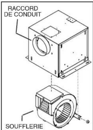
LOSONE SELECT® VENTILATOR
Ceiling/Wall Mount 120V
natural_image
Isometric diagram of a mechanical or architectural component with a circular inset showing a figure, no text or symbols present.READ AND SAVE THESE INSTRUCTIONS
WARNING


TO REDUCE THE RISK OF FIRE, ELECTRIC SHOCK, OR INJURY TO PERSONS, OBSERVE THE FOLLOWING:
- Use this unit only in the manner intended by the manufacturer. If you have questions, contact the manufacturer at the address or telephone number listed in the warranty.
- Before servicing or cleaning unit, switch power off at service panel and lock the service disconnecting means to prevent power from being switched on accidentally. When the service disconnecting means cannot be locked, securely fasten a prominent warning device, such as a tag, to the service panel.
- Installation work and electrical wiring must be done by a qualified person(s) in accordance with all applicable codes and standards, including fi re-rated construction codes and standards.
- Sufficient air is needed for proper combustion and exhausting of gases through the flue (chimney) of fuel burning equipment to prevent backdrafting. Follow the heating equipment manufacturer's guideline and safety standards such as those published by the National Fire Protection Association (NFPA), and the American Society for Heating, Refrigeration and Air Conditioning Engineers (ASHRAE), and the local code authorities.
- When cutting or drilling into wall or ceiling, do not damage electrical wiring and other hidden utilities.
- Ducted fans must always be vented to the outdoors.
- To reduce the risk of fire, use only metal ductwork.
- Never place a switch where it can be reached from a tub or shower.
- This unit must be grounded.
TO REDUCE THE RISK OF A RANGE TOP GREASE FIRE:
- Never leave surface units unattended at high settings. Boilovers cause smoking and greasy spillovers that may ignite. Heat oils slowly on low or medium settings.
- Always turn hood ON when cooking at high heat or when cooking flaming foods.
- Clean ventilating fans frequently. Grease should not be allowed to accumulate on fan or filter.
- Use proper pan size. Always use cookware appropriate for the size of the surface element.
TO REDUCE THE RISK OF INJURY TO PERSONS IN THE EVENT OF A RANGE TOP GREASE FIRE, OBSERVE THE FOLLOWING:\*
- SMOTHER FLAMES with a close-fitting lid, cookie sheet, or metal tray, then turn off the burner. BE CAREFUL TO PREVENT BURNS. If the flames do not go out immediately, EVACUATE AND CALL THE FIRE DEPARTMENT.
- NEVER PICK UP A FLAMING PAN — You may be burned.
- DO NOT USE WATER, including wet dishcloths or towels - violent steam explosion will result.
- Use an extinguisher ONLY if:
A. You know you have a Class ABC extinguisher and you already know how to operate it.
B. The fire is small and contained in the area where it started.
C. The fire department is being called.
D. You can fight the fire with your back to an exit.
* Based on "Kitchen Fire Safety Tips" published by NFPA.
CAUTION

- For general ventilating use only. Do not use to exhaust hazardous or explosive materials and vapors.
- To avoid motor bearing damage and noisy and/or unbalanced impellers, keep drywall spray, construction dust, etc. off power unit.
- Please read specification label on product for further information and requirements.
TABLE OF CONTENTS
This manual is divided into sections as follows:
"TYPICAL INSTALLATION"
This section shows a common installation in new and existing, frame construction.
- Mounting (new construction)
- Mounting (existing construction)
- Wiring
- Ducting (horizontal blower discharge)
"MOUNTING OPTIONS"
"WIRING OPTIONS"
-Wiring Plate Position
"DUCTING OPTIONS"
- Blower Discharge Positions
- Ducting (vertical blower discharge)
"USE AND CARE"
"SERVICE PARTS"
"WARRANTY"
Installer: Leave this manual with the homeowner.
Homeowner: Use and Care information on page 3.
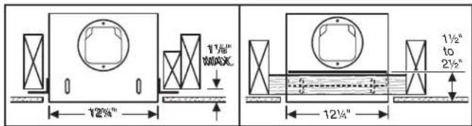
TYPICAL INSTALLATION
MOUNTING (New Frame Construction)
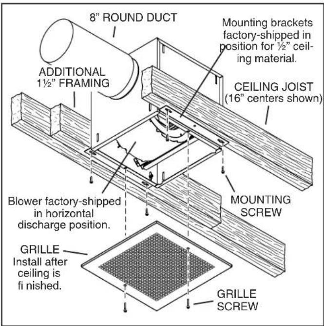
Factory-shipped unit installed in new construction.
MOUNTING (Existing Frame Construction)
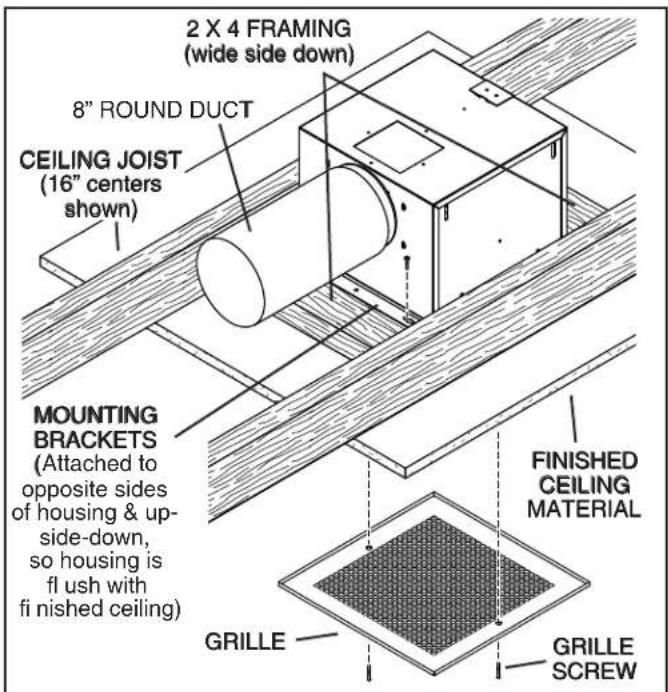
Factory-shipped unit installed in existing construction.
TYPICAL INSTALLATION
WIRING
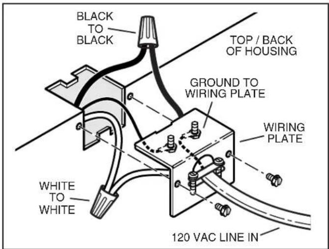
Ventilator can be wired from outside of housing. Use UL approved connectors to wire per local codes.
DUCTING (Horizontal blower discharge)
Two ways to connect ductwork to a factory-shipped unit.
IMPORTANT:
Remove shipping tape from damper
Remove the shipping tape from the damper flap and make sure that damper flap opens and closes freely inside the ductwork. Use duct tape to make ductwork connections secure and air-tight.
Remove shipping ring from blower inlet
Remove the shipping ring from the blower inlet before operating the ventilator.
MOUNTING OPTIONS
1/4-20 hex nuts secure mounting brackets to housing. Loosen and re-tighten or remove and replace nuts as necessary for desired mounting bracket position.
Mounting brackets in factory-shipped position. (Outlet parallel to joists.) (New construction)
Mounting brackets fl ipped over and mounted to outlet sides of housing.
(Outlet parallel to joists.)
(Existing construction)
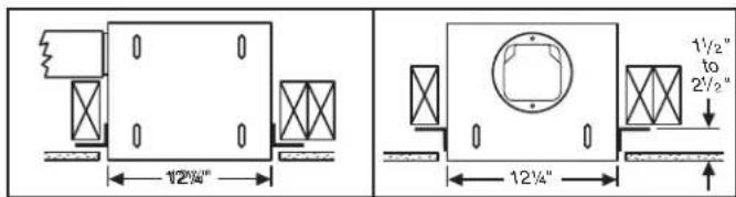
Mounting brackets mounted to outlet sides of housing. (Outlet perpendicular to joists.) (New construction)
Mounting brackets fl ipped over to give approx. 1" more clearance. (Outlet parallel to joists.) (New construction)
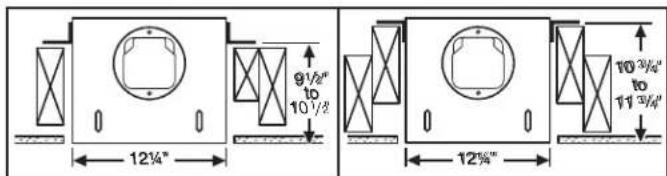
Mounting brackets mounted to top of sides of housing. (Outlet parallel to joists.) (New or existing construction)
Mounting brackets fl ipped over and mounted to top of sides of housing. (Outlet parallel to joists.) (New or existing construction)
WIRING OPTIONS
WIRING PLATE POSITION
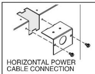
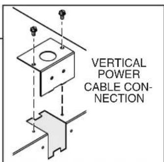
Wiring plate mounts to side or top of housing.
DUCTING OPTIONS
BLOWER DISCHARGE POSITIONS
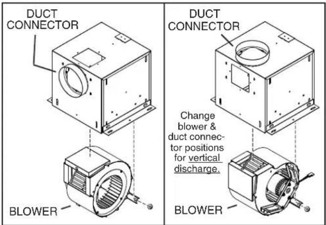
Blower and duct connector in horizontal discharge position. (Factory shipped)
Blower and duct connector in vertical discharge position.
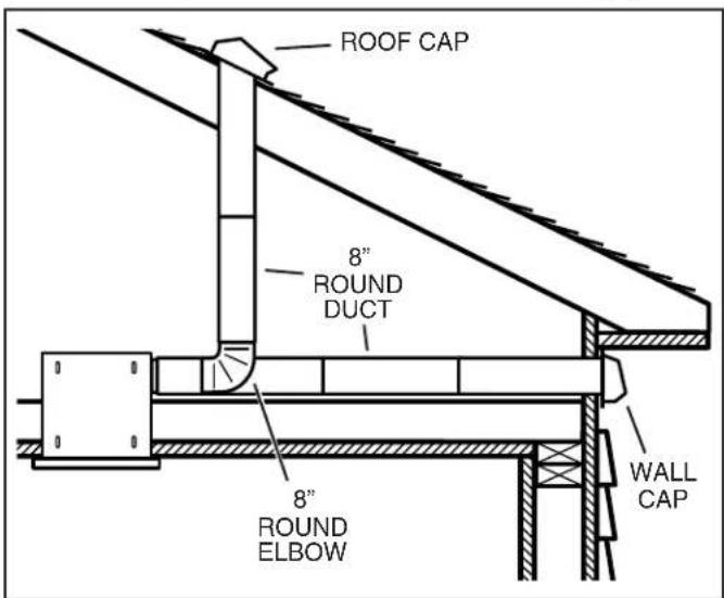
DUCTING (Vertical blower discharge)
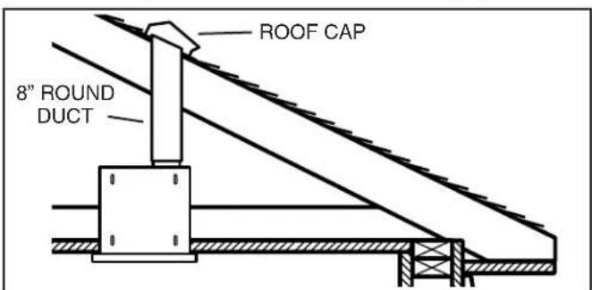
Typical ductwork connection to a ventilator converted to vertical discharge.
USE AND CARE
Ventilator is designed for continuous operation. If desired, it may be controlled using an on/off switch or a solid-state, variable speed control. Follow wiring instructions packed with control, and adhere to all local and state codes, and the National Electrical Code.
WARNING: To reduce the risk of electric shock, disconnect from power supply before servicing.
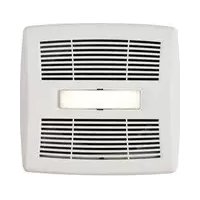
To clean grille: Use appropriate vacuum attachment or remove grille and clean with a soft cloth and mild soap or detergent. Dry grille thoroughly before reinstalling.
To clean blower assembly: Remove grille, unplug blower from housing, remove blower mounting nuts, and carefully remove blower from housing. Use appropriate vacuum attachment or a soft cloth and mild soap or detergent to clean blower discharge area and wheel. DO NOT ALLOW WATER TO ENTER MOTOR. Make sure blower assembly is completely dry before reinstalling.
Motor is permanently lubricated. Do not oil or disassemble motor.
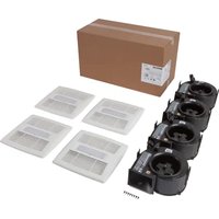
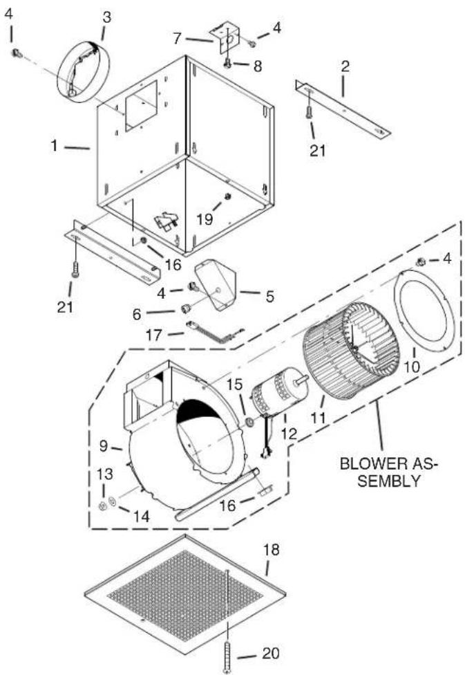
SERVICE PARTS SERVICE PARTS
| KEY NO. | PART NO. | DESCRIPTION |
| 1 | 97014726 | Housing Assembly |
| 2 97014728 | Mounting | Bracket (2 req.) |
| 3 | 97014761 | Damper Assembly |
| 4 99150415 | Screw, 8-18 x 1⁄4 (12 req.)* | |
| 5 98005513 | Wire Box | Cover |
| 6 99400085 | Strain Relief Bushing | |
| 7 | 98005512 | Wiring Plate |
| 8 99150471 | Ground Screw, 10-32 x 1⁄2 (2 req.) | |
| 9 | 97014775 | Scroll Assembly |
| 10 | 98009399 | Inlet Ring |
| 11 | 99020273 | Blower Wheel |
| 12 | 99080485 | Motor |
| 13 99260558 | Lock Nut, 8-32 (4 req.)* | |
| 14 99250959 | Washer (4 req.)* | |
| 15 99100491 | Grommet (4 req.) | |
| 97014814 Blower Assembly, Complete(Includes Key Nos. 9-15) | ||
| 16 99260477 | Nut, 1⁄4-20 (6 req.)* | |
| 17 | 97006039 | Wire Harness |
| 18 | 98009416 | Grille |
| 19 99420470 | Grille Nut (2 req.) | |
| 20 99150472 | Grille Mounting Screw (2 req.) | |
| 21 99150591 | Screw, 10-16 x 7/8 (4 req.)* | |
Order replacement parts by PART NO. - not by KEY NO.
* Standard hardware - may be purchased locally.
WARRANTY
BROAN-NUTONE ONE YEAR LIMITED WARRANTY
Broan-NuTone warrants to the original consumer purchaser of its products that such products will be free from defects in materials or workmanship for a period of one year from the date of original purchase. THERE ARE NO OTHER WARRANTIES, EXPRESS OR IMPLIED, INCLUDING, BUT NOT LIMITED TO, IMPLIED WARRANTIES OF MERCHANTABILITY OR FITNESS FOR A PARTICULAR PURPOSE.
During this one-year period, Broan-NuTone will, at its option, repair or replace, without charge, any product or part which is found to be defective under normal use and service.
THIS WARRANTY DOES NOT EXTEND TO FLUORESCENT LAMP STARTERS AND TUBES. This warranty does not cover (a) normal maintenance and service or (b) any products or parts which have been subject to misuse, negligence, accident, improper maintenance or repair (other than by Broan-NuTone), faulty installation or installation contrary to recommended installation instructions.
The duration of an implied warranty is limited to the one-year period as specified for the express warranty. Some states do not allow limitation on how long an implied warranty lasts, so the above limitation may not apply to you.
BROAN-NUTONE'S OBLIGATION TO REPAIR OR REPLACE, AT BROAN-NUTONE'S OPTION, SHALL BE THE PURCHASER'S SOLE AND EXCLUSIVE REMEDY UNDER THIS WARRANTY. BROAN-NUTONE SHALL NOT BE LIABLE FOR INCIDENTAL, CONSEQUENTIAL OR SPECIAL DAMAGES ARISING OUT OF OR IN CONNECTION WITH PRODUCT USE OR PERFORMANCE. Some states do not allow the exclusion or limitation of incidental or consequential damages, so the above limitation may not apply to you.
This warranty gives you specific legal rights, and you may also have other rights, which vary from state to state. This warranty supersedes all prior warranties.
To qualify for warranty service, you must (a) notify Broan-NuTone at the address or phone number stated below, (b) give the model number and part identification and (c) describe the nature of any defect in the product or part. At the time of requesting warranty service, you must present evidence of the original purchase date.
In the U.S., contact: Broan-NuTone LLC, 926 West State Street, Hartford, WI 53027 (1-800-637-1453)
In Canada, contact: Broan-NuTone Canada, 1140 Tristar Drive Mississauga, Ontario L5T 1H9 (1-888-882-7626)
VENTILADOR LOSONE SELECT®
natural_image
3D diagram of a mechanical component with a circular inset showing a cross-section (no text or symbols)Página 5
LEA Y CONSERVE ESTAS INSTRUCCIONES
ADVERTENCIA


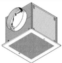
natural_image
Isometric diagram of a 3D cube with a circular component and a mesh pattern inside, no text or symbols present.LIRE ET CONSERVER CES INSTRUCTIONS
AVERTISSEMENT
POUR RÉDUIRE LE RISQUE D'INCENDIE, DE CHOC ÉLECTRIQUE OU DE BLESSURES PERSONNELLES, OBSERVEZ CE QUI SUIT:
OPTIONS D'INSTALLATION DES CONDUITS
POSITIONS DE LA DÉCHARGE DE LA SOUFFLERIE