
Elements Gala Sub 15 - Speaker HK AUDIO - Free user manual and instructions
Find the device manual for free Elements Gala Sub 15 HK AUDIO in PDF.
| Product Type | Active subwoofer with Mid/High columns (Line Array system) |
| Brand | HK Audio |
| Model | Elements Gala Sub 15 |
| RMS Power | 670 W (Class D) |
| Peak Power | 2000 W |
| Max SPL | 129 dB |
| Frequency Response | 44 Hz - 130 Hz (±5 dB) |
| Speaker | 1 x 15" |
| Inputs | 2 x balanced combo XLR/jack |
| Outputs | 2 x XLR Thru, 2 x Speakon (Mid/High Out) |
| Power Supply | 220-240 V~, 50/60 Hz, 1.7 A (peak current 3.5 A) |
| Dimensions (W x H x D) | 48 x 48.5 x 59.5 cm |
| Weight (subwoofer) | 30.2 kg |
| Total system weight | 55.6 kg (with columns and tripods) |
| Cabinet material | MDF, black acrylic lacquer |
| Grille | Metal grille with black acoustic foam |
| DSP functions | Subsonic filter 24 dB, peak/RMS/multiband limiters, EQ Small Venue / Long Distance |
| Auto Sleep | Yes, can be disabled (standby after 350 min, consumption 0.5 W) |
| Maintenance | Clean with a dry cloth; do not open the cabinet |
| Safety | Do not expose to moisture; use a V-Lock power cable; follow assembly instructions |
| Included accessories | 4x E 835, 2x EF 45, 2x EP 2, Speakon cables, V-Lock power cable, locking wedges |
Frequently Asked Questions - Elements Gala Sub 15 HK AUDIO
User questions about Elements Gala Sub 15 HK AUDIO
0 question about this device. Answer the ones you know or ask your own.
Ask a new question about this device
Download the instructions for your Speaker in PDF format for free! Find your manual Elements Gala Sub 15 - HK AUDIO and take your electronic device back in hand. On this page are published all the documents necessary for the use of your device. Elements Gala Sub 15 by HK AUDIO.
USER MANUAL Elements Gala Sub 15 HK AUDIO
Important Safety Instructions! Read before connecting!
This product has been built by the manufacturer in accordance with IEC 60065 and left the factory in safe working order. To maintain this condition and ensure non-risk operation, the user must follow the advice and warning comments found in the operating instructions. If this product shall be used in vehicles, ships or aircraft or at altitudes exceeding 2000m above sea level, take care of the relevant safety regulations which may exceed the IEC 60065 requirements. WARNING: To prevent the risk of fire and shock hazard, do not expose this appliance to moisture or rain. Do not open case - no user serviceable parts inside. Refer service to qualified service personnel.

This symbol, wherever it appears, alerts you to the presence of undulated dangerous voltage inside the enclosure - voltage that is sufficient to constitute a risk of shock.

This symbol, wherever it appears, alerts you to the presence of a fully accessible hazardous voltage. External wiring connected to terminal marked with this symbol must be a "ready made complying with the manufacturers recommendations, or must being installed by instructed persons only.

This symbol, wherever it appears, alerts you to important aging and maintenance instructions in the accompanying text. Read the manual.

This symbol, wherever it appears, tells you: Take care! Hot To prevent burns you must not touch.

All electrical and electronic products including batteries be disposed of separately from the municipal waste stream via fixed collection facilities appointed by the government or the authorities.

Read these instructions. Keep these instructions. Follow all steps and instructions marked on the product and in this manual.
- Do not use this product near water. Do not place the product near water, baths, wash basins, kitchen sinks, wet areas, swimming pools or damp rooms.
- Do not place objects containing liquid on the product - vases, glasses, bottles etc.
Clean only with dry cloth. - Do not remove any covers or sections of the housing.
- The set operating voltage of the product must match the local mains supply voltage. If you are not sure of the type of power available consult your dealer or local power company.
- Before connecting the device, please ensure that the mains supply you are using is equipped with adequate protection against short circuiting and grounding faults when the device is plugged in.
To reduce the risk of electrical shock, the grounding of this product must be maintained. Use only the power supply cord provided with this product, and maintain the function of the center (grounding) pin of the mains connection at any time. Make sure the mains outlet used provides a proper protective ground connection. - Do not defeat the safety purpose of the polarized or grounding-type plug. A polarized plug has two blades with one wider than the other. A grounding type plug has two blades and a third grounding prong. The wide blade or the third prong are provided for your safety. If the provided plug does not fit into your outlet, consult an electrician for replacement of the obolete outlet.
- Protect the power cord from being walked on or pinched particularly at plugs, convenience receptacles, and the point where they exit from the device! Power supply cords should always be handled carefully. Periodically check cords for cuts or sign of stress,
especially at the plug and the point where the cord exits the device. - Never use a damaged power cord.
-
Unplug this product during lightning storms or when unused for long periods of time.
-
This product can be fully disconnected from mains only by pulling the mains plug at the unit or the wall socket. The product must be placed in such a way at any time, that disconnecting from mains is easily possible.
Fuses: Replace with IEC127 (5x20mm) type and rated fuse for best performance only. It is prohibited to use "patched fuses" or to short the fuse-holder. Replacing any kind of fuses must only be carried out by qualified service personal.
Refer all servicing to qualified service personnel. Servicing is required when the unit has been damaged in any way, such as: - When the power cord or plug is damaged or frayed.
- If liquid has been spilled or objects have fallen into the product.
- If the product has been exposed to rain or moisture.
If the product does not operate normally when the operating instructions are followed. - If the product has been dropped or the cabinet has been damaged.
- Do not connect external speakers to this product with an impedance lower than the rated impedance given on the product or in this manual. Use only cables with sufficient cross section according to the local safety regulations.
- Keep away from direct sunlight.
- Do not install near heat sources such as radiators, heat registers, stoves or other devices that produce heat.
- This apparatus is for moderate climates areas use, not suitable for use in tropical climates countries.
- Do not block any ventilation openings. Install in accordance with manufacturer's instructions. This product must not be placed in a built-in installation such as a rack unless proper ventilation is provided.
- Always allow a cold device to warm up to ambient temperature, when being moved into a room. Condensation can form inside it and damage the product, when being used without warming up.
- Do not place naked flame sources, such as lighted candles on the product.
The device must be positioned at least 20~cm / 8^ away from walls. - Use only with the cart, stand, tripod, bracket or table specified by the manufacturer or sold with the product. When a cart is used, use caution when moving the cart/product combination to avoid injury from tip-over.
- Use only accessories recommended by the manufacturer, this applies for all kind of accessories, for example protective covers, transport bags, stands, wall or ceiling mounting equipment. In case of attaching any kind of accessories to the product, always follow the instructions for use, provided by the manufacturer. Never use fixing points on the product other than specified by the manufacturer.
- This appliance is NOT suitable to be used by any person or persons (including children) with limited physical, sensorial or mental ability, or by persons with insufficient experience and/or knowledge to operate such an appliance. Children under 4 years of age must be kept away from this appliance at all times.
- Never push objects of any kind into this product through cabinet slots as they may touch dangerous voltage points or short out parts that could result in risk of fire or electric shock.
- This product is capable of delivering sound pressure levels in excess of 90 dB, which may cause permanent hearing damage. Exposure to extremely high noise levels may cause a permanent hearing loss. Wear hearing protection if continuously exposed to such high levels.
- The manufacturer only guarantees the safety, reliability and efficiency of this product if:
Assembly, extension, re-adjustment, modifications or repairs are carried out by the manufacturer or by persons authorized to do so.
The electrical installation of the relevant area complies with the requirements of IEC (ANSI) specifications. - The unit is used in accordance with the operating instructions.
- This product is optimized for use with music and speech signals. Using this product with sine wave, square wave or other kind of measuring signals at higher level may lead to severe damage of the product.
General Notes on Safety for Loudspeaker Systems

- Mounting systems may only be used for those loudspeaker systems authorized by the manufacturer and only with the mounting stories specified by the manufacturer in the installation actions. Read and heed the manufacturer's installation actions. The indicated load-bearing capacity cannot be altered and the manufacturer will not be liable for damages in the event of improper installation or the use of unauthorized mounting stories.
The system's load-bearing capacity cannot be guaranteed and the manufacturer will not be liable for damages in the event that loudspeakers, mounting accessories, and connecting and attaching components are modified in any way.
Components affecting safety may only be repaired by the manufacturer or authorized agents, otherwise the operating permit will be voided.

Installation may be performed qualified personnel only, given only at pick-points with sufficient load-carrying capacity and compliance with local building regulations. Use only the existing hardware specified by the manufacturer in the installation actions (screws, anchors, etc.). Take all the precautions necessary to ensure bolted connections and other threaded locking devices will be open.

Fixed and portable installations (in this case, speakers mounting accessories) must be secured by two independent ties to prevent them from falling. Safeties must be able to accessories or parts that are loose or may become loose. compliance with the given national regulations when using acting, attaching, and rigging devices. Factor potential dynamic (jerk) into the equation when determining the proper size and wearing capacity of safeties.

1 Be sure to observe speaker stands' maximum load-bearing capacity. Note that for reasons of design and construction, most center stands are approved to bear centric loads only; that is, the speakers' mass has to be precisely centered and balanced. Ensure center stands are set up stably and securely. Take appropriate added measures to secure speaker stands, for example when:
- the floor or ground surface does not provide a stable, secure base.
they are extended to heights that impede stability.
- high wind pressure may be expected.
there is the risk that they may be knocked over by people.
Special measures may become necessary as precautions against unsafe audience behavior. Do not set up speaker stands in evacuation routes and emergency exits. Ensure corridors are wide enough and put proper barriers and markings in place when setting speaker stands up in passageways. Mounting and dismounting are especially hazardous tasks. Use aids suitable for this purpose. Observe the given national regulations when doing so.

Wear proper protection (in particular, a helmet, boots, and safety shoes) and use only suitable means of ascent (e.g., scaffolds, etc.) during installation. Compliance with this element is the sole responsibility of the company performing the installation.

WARNING: After installation, inspect the system comprised mounting fixtures and loudspeakers to ensure it is properly d.
The operator of loudspeaker systems (fixed or portable) must regularly inspect or task a third party to regularly inspect all system components in accordance with the given country's regulations and have possible defects repaired immediately.
We also strongly recommend maintaining a logbook or the like to document all inspections.
When installing speakers for longer lasting or permanent outdoor operation, be sure to take into account the stability and load-bearing capacity of platforms and surfaces; loads and forces exerted by wind, snow, and ice; as well as thermal influences. Also be sure to provide sufficient safety margins for the rigging points used for flow systems. Observe the given national regulations when doing so.
- Ask the manufacturer if your product is allowed for outdoor usage!

Professional loudspeaker systems can produce harmful noise levels. Even prolonged exposure to seemingly harmless levels (e.g. at about 95 dB SPL) can cause permanent hearing damage. We therefore recommend that everyone who is exposed to high noise levels produced by loudspeaker systems wears professional hearing protection (earplugs or earmuffs).
Manufacturer: Stamer Musikanlagen GmbH, Magdeburger Str. 8, 66606 St. Wendel, Germany
ELEMENTS GALA
Welcome to the HK Audio family!
Thank you for choosing a brand-name product made by our company. Rest assured, we engineered and built it with the greatest care so it will serve you well for many tomorrows to come.

Even if your experience with sound systems runs deep, some things about this product are sure to be new to you. This is why we ask that you do not set this manual aside without reading it first. Be sure to keep it in a safe place for later reference.
Here's wishing you the best sound at every occasion!
Your HK Audio team
Warranty
Use the convenient online registration option at www.hkaudio.com.

http://warranty.hkaudio.com
The registration is only valid if the device is registered within 30 days of the date of purchase.
HK AUDIO
Technischer Service
Postfach 1509
66595 St. Wendel, Germany
Fax:+496851905100

Powerful electromagnetic interference and electrostatic discharges may impair this unit's operation. In the event of such interference, switch the device off and back on again. If this fails to restore the normal mode of operation, please move the unit away from the source of interference and try again.
1 General Information
Unpacking and Inventorying
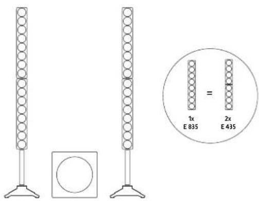
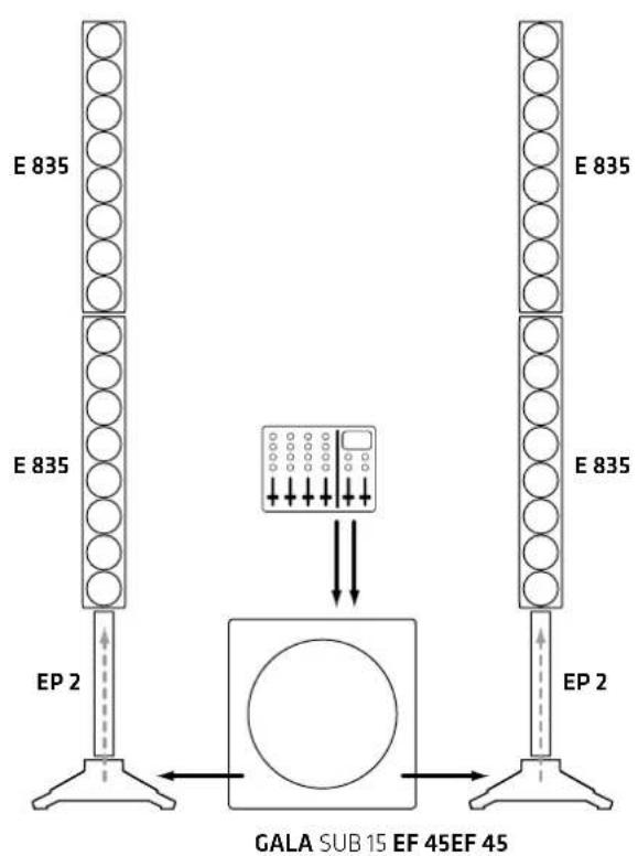
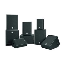
When you first unpack ELEMENTS GALA, take a quick inventory to make sure the package comes complete with all the contents. The system consists of the GALA SUB 15 powered subwoofer, four E 835 mid/high units, two each EF 45 bases and two EP 2 speaker extension poles with a built-in signal bus. It also comes with a matching V-Lock mains cable, two speaker cords equipped with Speakon connectors, and four locking wedges to fix the mid/high units in place so they can't turn to the left or right.
Heads up: If you purchased the GALA SUB 15 subwoofer separately, please be advised that this powered speaker may only be operated with the aforementioned ELEMENTS components.
The System's Components
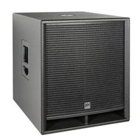
The Subwoofer GALA SUB 15
The GALA SUB 15 subwoofer is loaded with a 15" woofer; it houses the system's active circuitry and the Class D power amplifiers. The connection and control panel is on the rear.
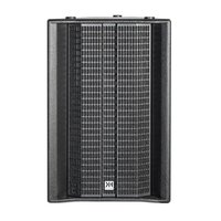
Mid/High Columns
The two columns consist of two E 835s each for a grand total of 32.5^ full-range speakers. These operate on the same principle as big line arrays. The built-in E-Connect signal bus provides a cordless link between the column's components. The EF 45 base features two parallel Speakon NL4 inputs and an E-Connect docking port.
Heads up! The system's components are matched for the best possible audio performance and may only be operated in the specified config guration. The use of satellites other than these will not only degrade the sound; it may also damage the power amp as well as connected outboard devices.
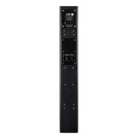
2 Connectors and Controls
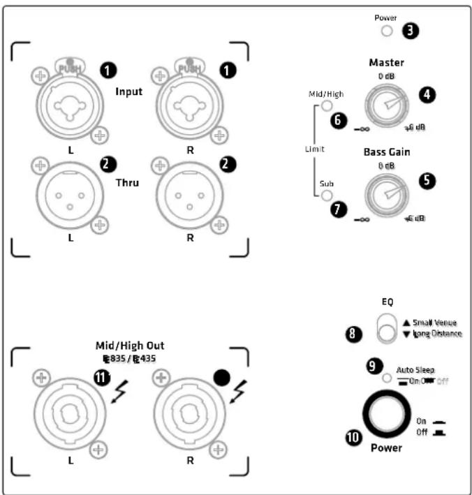
1 Input
Plug a cord equipped with an XLR connector or 1/4''/6.35 mm jack plug into this electronically balanced XLR/ 1/4''/6.35 mm combo input to send a L/R stereo line signal from your DJ controller, mixing console, keyboard or the like to the system.
2 Thru
These balanced parallel XLR outputs serve to send the L/R stereo signal routed into Input (1) through to other components such as powered monitors. The Thru jacks also connect the optional HK Audio LINEAR SUB series model L SUB 1500 A subwoofer. This bass bin comes highly recommended if you wish to boost your system's low-end performance.
3 Power LED
This LED lights up green when the Power button (10) is set to On and the unit is getting mains power.
4 Master
The Master knob adjusts the gain and thus the volume for the entire ELEMENTS GALA system. Turn it all the way down—that is, as far left as it will go—before switching on the system.
Sub
The Sub knob adjusts the subwoofer's volume separately. The mid/high units and the subwoofer's volume levels are relatively balanced when the knob is set to 0 dB—that is, the center-notched 12 o'clock position.
Limit Mid/High
This LED tells you the limiter is operating in the mid/high columns' frequency range.
Heads up! If the Mid/High LED stays red while the system is up and running, it is being overloaded. Turn down the Master knob! If you are not feeding a signal into the system and the LED stays red, there has been malfunction. Contact our Technical Service.
Limit Sub
This LED tells you the limiter is operating in the GALA SUB 15 subwoofer's low frequency range.
Heads up! If the Sub LED stays red while the system is up and running, it is being overloaded. Turn down the Master knob! If you are not feeding a signal into the system and the LED stays red, there has been malfunction. Contact our Technical Service.
8 Small Venue/ Long Distance Selector
This DSP-driven EQ optimizes the frequency response for the given application.
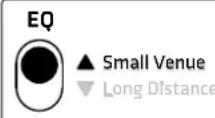
Small Venue: As the name suggests, the Small Venue filtering setting voices the mid/high columns' frequency response for smaller rooms. The system will then deliver a signal that sounds balanced and remarkably transparent even at very short range.
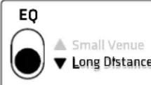
Long Distance: Set the switch to Long Distance when you want to voice the mid/high columns' frequency response for larger rooms. This setting maximizes the speakers' reach to throw high and mid-range frequencies all the way to the back row, yet retains the system's excellent sound quality.
9 Auto Sleep
ELEMENTS GALA SUB 15's Auto Sleep mode is enabled when the button is set to On. If the system is left to idle for 350 minutes without receiving a signal, the amp switches to this power-saving mode where it consumes around 0.5 watts. To wake it up, first press the power button to switch the system off for five seconds. Then switch it on again to bring ELEMENTS GALA SUB 15 back on line. Set Auto Standby to the Off position if you wish to disable this function and ensure ELEMENTS GALA SUB 15 remains up and running.
10 Power
This is ELEMENTS GALA SUB 15's on/off button. The power LED lights up green when it is engaged.
Mid/High Out
Plug speaker cords equipped with NL2 Speakon connectors (+1/-1; at least 1.5mm^2 in diameter) into these outputs to connect the ELEMENTS GALA system's mid/high columns. Do not use these outputs to connect any component apart from the E 835 (E 435) mid/high units. If you connect another device, you stand a good chance of destroying it and the GALA SUB 15 bass bin.
Note: Be sure to rotate speaker connectors clockwise until they lock in place! Heads up: This type of connector has to be turned clockwise until it engages. It also has to be disengaged before it can be unplugged. To this end, pull the bayonet catch towards the cord and turn the connector counter-clockwise.
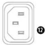
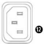
12 Mains
Use the factory-included mains cord to connect this socket to a wall outlet.
Heads up: The GALA SUB 15 subwoofer comes with a V-Lock mains socket. It lets you fi x the included V-Lock mains cord in place to prevent accidental disconnection.
Mains
220-240V--50-60W 1.7A rated current
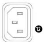

Caution! Make sure the local mains voltage times the voltage specified on the GALA SUB 15 subwoofer.
Connecting it to the wrong mains voltage may destroy its electronic components.

Speaker Input on the EF 45 Base
(not pictured)
To connect the two mid/high columns to the subwoofer, plug one end of each of the two included speaker cables into the speaker input jacks on the EF 45 base and the other into the subwoofer's Mid/High Out L/R outputs, respectively (1). The E-Connect bus routes the signal to the connected mid/high units. You can, of course, assemble columns without the EP 2 extension poles.
3 Setting Up and Connecting the Column's Components
3.1 E-Connect
E-Connect is a fast, reliable and cordless way of linking the ELEMENTS GALA's passive components. This dual-purpose coupler provides physical and audio links that connect the E 835 mid/high-units, the EP1 speaker extension pole and the EF45 base.
3.2 Connecting the Column's Components
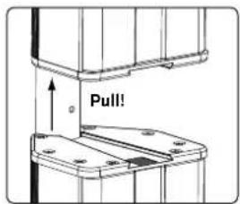
Line up the two components so that the pole end faces the sleeve. Insert the pole end all the way into sleeve until the detent button snaps into place, making sure you have a solid connection.
To disconnect and separate the units, press and hold the button on the E-Connector to release the detent and then pull the two components apart.
Heads up: Always set the system up on flat, level and firm surfaces.
4 Powering Up
- Make sure the GALA SUB 15 bass bin is switched off when you're setting up; otherwise, the system may be damaged. Turn the Bass Gain knob to the 0 dB center-notched position.
- Always set up the entire system and connect all cables before you switch the GALA SUB 15 bass on.
- Always switch off the GALA SUB 15 first when taking the system down.
5 Setting Up
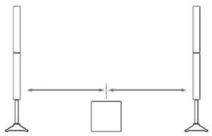
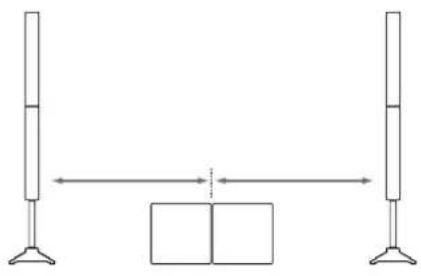
5.1 Placement
The subwoofer needs to be centered between the two columns for the system to deliver a balanced stereo image.
5.2 Vertical Alignment
What height is right?
Line array systems like ELEMENTS deliver a fairly narrow vertical output pattern. This is why you want to aim the speakers so the center of the column is roughly in line with the audience's heads. If you're setting the system up on a raised platform such as a stage, please do so without using the EP 2 extension pole.
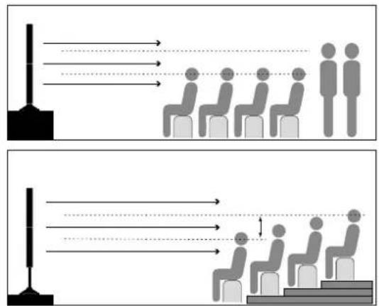
If there's no riser or other platform available, use the EP 2 extension pole to adjust the speakers' height to the proper level.
5.3 Horizontal Alignment
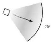
A mid/high column's horizontal directivity is around 70^ . Depending on the application, you may want to turn the columns inwards towards the audience area to direct the system's power where it is needed most.
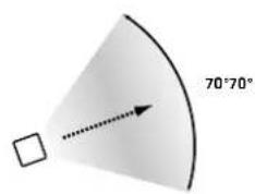
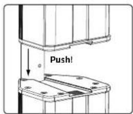
You'll get the best sound and coverage when all connected components project at the same angle. The included locking wedges lets you lock down the ELEMENTS mid/high-units so their aim remains true and they can't drift to the left or right.
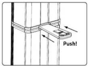
Insert the locking wedge into the slot until it clicks into place. Apply slight pressure to the center panel to release and remove it.
6 L SUB 1500 A Bass Extension
You can also extend the ELEMENTS GALA system with an added bass bin, the HK Audio L SUB 1500 A powered subwoofer.
To do this, use two XLR-equipped cords to connect the GALA SUB 15 subwoofer's Thru L/R ports (2) to the L SUB 1500 A subwoofer's L/R Inputs.
Place the two subwoofoers next to each other, preferably centered between the two mid/high columns, for the system to deliver a balanced audio image.
7 Optional HK Audio Accessories
1. ELEMENTS BASE BAG
Padded soft case for one EF 45 base
2. ELEMENTS SOFT BAG
Padded soft case for two E 835 units and one EP 2 pole
3. GALA SUB 15 ROLLER BAG
Padded soft case for the subwoofer with an integrated dolly board
4.100 mm BLUE SWIVEL CASTERS
The optional swivel castors are mounted to the rear of the GALA SUB 15 subwoofer using the self-locking screws at the corners.
Heads up: The subwoofer does not fit in the GALA SUB 15 ROLLER BAG with the swivel casters mounted. However, it will fit in the soft case for the L SUB 1500 A add-on subwoofer.
8 Technical Specific cations
| ELEMENTS GALA System | |
| Total power output (RMS)1 | 570 W Class D |
| Calculated peak power 2000 | W |
| Components 1x GALA SUB 15, 4x E 835, 2x EF 45, 2x EP 2 | |
| DSP features 24 dB subsonic | fi Iter, peak, RMS and multi-band limiters |
| Optional accessories ELEMENTS BASE BAG, ELEMENTS SOFT BAG, GALA SUB 15 ROLLER BAG, EF 45, EP 2 | |
| Total weight 55.6 kg / 122.6 lbs. | |
| ELEMENTS GALA SUB 15 | |
| Max SPL peak2 129 dB | |
| Frequency response +/-5 dB | 44 Hz - 130 Hz, 24 dB/oct. |
| Inputs | 2x XLR/ 1/4" (6.35 mm) combo inputs |
| Outputs | 2x XLR Thru, 2x Mid/High Out (Speakon) |
| Woofer | 1x 15" |
| Housing | MDF |
| Finish | Black acrylic enamel |
| Front grille | Metal grille backed with black acoustic foam |
| Grips | 2x HK Audio MultiGrip |
| Dimensions (WxHxD) | 48 x 48.5 x 59.5 cm |
| Weight | 30.2 kg / 66.6 lbs. |
| E 835 Mid/High Unit | |
| Power handling, nominal(RMS) | 300 W @ 8 ohms |
| Axial sensitivity 1W/1m | 100 dB Halfspace |
| Frequency response -10 dB | 140 Hz - 20 kHz |
| Speakers | 8 x 3.5" broadband |
| Directivity | 70° horizontal |
| Corner frequency | 140 Hz, 30 dB/oct. |
| Connectors | 1x E-Connect In, 1x E-Connect Out |
| Dimensions (WxHxD) | 11 x 74.5 x 12 cm (excl. E-Connect sleeves) |
| Weight | 4.5 kg / 9.9 lbs. |
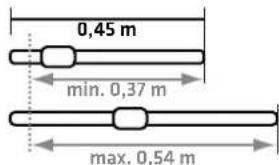
| EP 2 | |
| Dimensions (WxHxD) (for transportation) | 45 x 3.5 x 3.5 cm |
| Weight | 0.45 kg / 1 lbs. |
| EF 45 | |
| Dimensions (WxHxD) (for transportation) | 41 x 36 x 12.5 cm |
| Weight | 7.7 kg / 16.9 lbs. |
| General Technical Specifications | |
| Peak current | 3.5 A / 100-120 V AC • 1.7 A / 220-240 V AC |
| Inrush current | 39 A at 120 V and 230 V |
Short-term RMS value measured using a sine burst signal with a 1/4 cycle rate and a resulting crest factor of 9 dB at a frequency that is representative of the system
^2 @10% THD, Halfspace
8 Wahlschalter "Small Venue/ Long Distance"
Mains
220-240V-50-60A 1.7A rated current:

Mains 220-240V-50-601.7A rated current:

8 Selector "Small Venue/ Long Distance"

- Important Safety Instructions! Read before connecting!
- General Notes on Safety for Loudspeaker Systems
- ELEMENTS GALA
- Welcome to the HK Audio family!
- Your HK Audio team
- Warranty
- HK AUDIO
- General Information
- Unpacking and Inventorying
- The System's Components
- The Subwoofer GALA SUB 15
- Mid/High Columns
- Connectors and Controls
- Input
- Thru
- Power LED
- Master
- Sub
- Limit Mid/High
- Limit Sub
- Small Venue/ Long Distance Selector
- Auto Sleep
- Power
- Mid/High Out
- Mains
- Speaker Input on the EF 45 Base
- Setting Up and Connecting the Column's Components
- E-Connect
- Connecting the Column's Components
- Powering Up
- Setting Up
- Placement
- Vertical Alignment
- What height is right?
- Horizontal Alignment
- L SUB 1500 A Bass Extension
- Optional HK Audio Accessories
- ELEMENTS BASE BAG
- ELEMENTS SOFT BAG
- GALA SUB 15 ROLLER BAG
- mm BLUE SWIVEL CASTERS
- Technical Specific cations
- Wahlschalter "Small Venue/ Long Distance"
- Selector "Small Venue/ Long Distance"
Brand : HK AUDIO
Model : Elements Gala Sub 15
Category : Speaker