IR2000 - Thermometer Klein Tools - Free user manual and instructions
Find the device manual for free IR2000 Klein Tools in PDF.
| Brand | Klein Tools |
| Model | IR2000 |
| Category | Professional infrared thermometer |
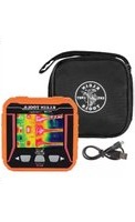
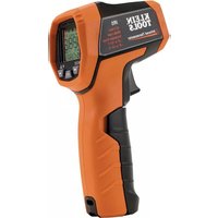
| Product type | Infrared thermometer with dual laser and Type K thermocouple input |
| Measurement range | -76 to 1022 °F (-60 to 550 °C) |
| Optical resolution (distance-to-target ratio) | 12:1 |
| Emissivity | Adjustable from 0.10 to 1.00 |
| Accuracy (at 77 °F / 25 °C) | ±1.8 °F (±1.0 °C) |
| Display | LCD screen with backlight |
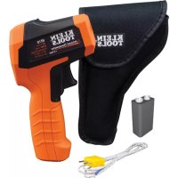
| Power supply | 2 AAA alkaline batteries |
| Battery life | Approximately 180 hours (without laser or backlight) |
| Dimensions | 119 x 30 x 172 mm (4.7 x 1.2 x 6.76 in) |
| Weight | 255 g (9.0 oz) |
| Laser | Class II, power < 1 mW, wavelength 635-660 nm |
| Operating temperature | 0 to 50 °C (32 to 122 °F) |
| Storage temperature | -10 to 60 °C (14 to 140 °F) |
| Operating relative humidity | 10 to 90% non-condensing |
| Maximum operating altitude | 3000 m |
| Certifications | CE, RoHS, FDA and IEC Class II for laser |
| Warranty | 2 years |
| Key features | IR and thermocouple K measurements, MAX/MIN/DIF/AVG modes, high/low alarms, auto-scan lock, automatic data hold |
| Maintenance and cleaning | Clean the housing with a damp cloth; lens with a cotton swab moistened with water or rubbing alcohol |
| Safety | Do not point the laser at eyes; avoid strong electromagnetic fields |
| Customer service | Klein Tools, 1-877-775-5346, www.kleintools.com |
Frequently Asked Questions - IR2000 Klein Tools
User questions about IR2000 Klein Tools
0 question about this device. Answer the ones you know or ask your own.
Ask a new question about this device
Download the instructions for your Thermometer in PDF format for free! Find your manual IR2000 - Klein Tools and take your electronic device back in hand. On this page are published all the documents necessary for the use of your device. IR2000 by Klein Tools.
USER MANUAL IR2000 Klein Tools
For Professionals...Since 1857
ENGLISH
IR2000
Instruction Manual
GENERAL SPECIFICATIONS
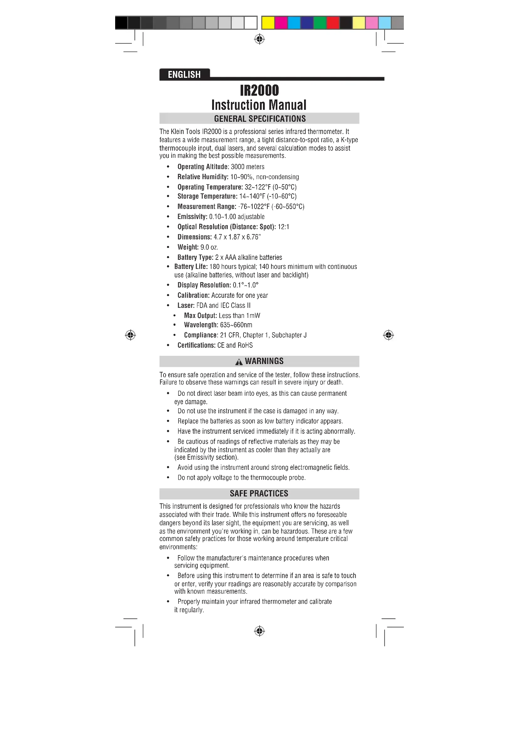
The Klein Tools IR2000 is a professional series infrared thermometer. It features a wide measurement range, a tight distance-to-spot ratio, a K-type thermocouple input, dual lasers, and several calculation modes to assist you in making the best possible measurements.
- Operating Altitude: 3000 meters
Relative Humidity: 10 90% non-condensing
Operating Temperature: 32 122^ (0 50^)
Storage Temperature: 14 - 140^ (-10 - 60^)
Measurement Range: -76~1022°C (-60~550°C) - Emissivity: 0.10~1.00 adjustable
Optical Resolution (Distance: Spot): 12:1
Dimensions: 4.7 × 1.87 × 6.76
Weight: 9.0 oz. - Battery Type: 2 x AAA alkaline batteries
- Battery Life: 180 hours typical; 140 hours minimum with continuous use (alkaline batteries, without laser and backlight)
Display Resolution: 0.1^ 1.0^ - Calibration: Accurate for one year
Laser: FDA and IEC Class II
Max Output: Less than 1mW
Wavelength: 635~660nm
Compliance: 21 CFR, Chapter 1, Subchapter J
Certifications: CE and RoHS
WARNING
To ensure safe operation and service of the tester, follow these instructions. Failure to observe these warnings can result in severe injury or death.
- Do not direct laser beam into eyes, as this can cause permanent eye damage.
- Do not use the instrument if the case is damaged in any way.
- Replace the batteries as soon as low battery indicator appears.
- Have the instrument serviced immediately if it is acting abnormally.
- Be cautious of readings of reflective materials as they may be indicated by the instrument as cooler than they actually are (see Emissivity section).
- Avoid using the instrument around strong electromagnetic fields.
- Do not apply voltage to the thermocouple probe.
SAFE PRACTICES
This instrument is designed for professionals who know the hazards associated with their trade. While this instrument offers no foreseeable dangers beyond its laser sight, the equipment you are servicing, as well as the environment you're working in, can be hazardous. These are a few common safety practices for those working around temperature critical environments:
- Follow the manufacturer's maintenance procedures when servicing equipment.
Before using this instrument to determine if an area is safe to touch or enter, verify your readings are reasonably accurate by comparison with known measurements. - Properly maintain your infrared thermometer and calibrate it regularly.

SYMBOLS

Laser Warning or Caution

Dangerous levels

Follow safe disposal procedures

Battery
THERMOMETER ATTRIBUTES
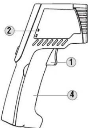

- Trigger: Initiates measurement.
- Thermocouple Input: Optional K-Type thermocouple measurement.
- IR Sensor: Collects temperature data.
- Battery Compartment: Pops forward to store 2 x AAA batteries.
- Dual Laser: Provides an approximate target area for making measurements.
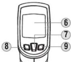
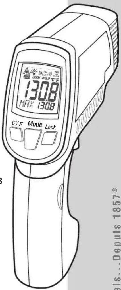
- LCD Screen: Displays measurement and additional information.
7.Mode Button: Changes the mode of the secondary display. - Down Button: Changes temperature scale, decreases threshold, decreases emissivity, or toggles laser depending on the mode.
- Up Button: Enters auto-scan (trigger lock) mode, increases threshold, increases emissivity, or toggles backlight depending on the mode.

OPERATING INSTRUCTIONS
Temperature Measurement
To take measurements with your IR2000, aim the instrument at the object to be measured and pull the trigger. The unit has an auto off after releasing the trigger of 60 seconds.
Targeting
The IR2000 features a dual laser to assist in targeting the area to be measured. The distance between the two lasers approximates the diameter of the circular spot focused on by the infrared sensor. This area will become larger as the target surface moves further away from gun (see Distance to Spot Ratio for more information). The approximation will be mostly accurate at a minimum distance of 12^ from the IR2000.
Selecting Temperature Scale
Press the Down Key while in display mode or any measurement mode to alternate between Fahrenheit and Celsius. You can select either scale during or after measurement, and when viewing any of the held values.
Lock Mode (Auto-Scan)
In lock mode, the IR2000 will take measurements continuously without holding down the trigger. The trigger can be held down to activate the laser, but is not required.
Auto Hold
The IR2000 will hold the last temperature measured for 60 seconds after the trigger is released. To recall this value or associated calculations press the MODE key to activate the display and show the held temperature.
In probe mode, the unit will automatically power off after 12 minutes. In auto-scan mode, the unit will automatically power off after 60 minutes.
Toggling Laser & Backlight
To toggle the laser, hold down the trigger and press the Down Key. To toggle the backlight, hold down the trigger and press the Up Key.
Thermocouple Probe Mode
The IR2000 can measure the temperature from a K-Type thermocouple probe. Press the mode key to enter Probe Mode. The measured temperature will automatically be displayed. To see the minimum or maximum temperature taken by the probe, press and hold the Down Button or Up Button, respectively.
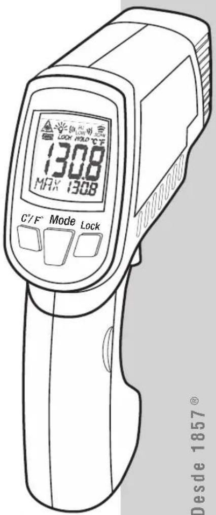
LCD SYMBOLS

Laser is active

The backlight is on.

The last measurement taken is being shown.

The thermometer is currently taking measurements.

Auto-scan mode is active.

Celsius or Fahrenheit temperature scale.

Battery is OK.

Battery is low and should be replaced.

Battery is exhausted. Replacement necessary before use.

GRAPHICS DRAWING NAME:
GRAPHICS PART NUMBER:
PACKAGING DWG. REF.: NA
IR2000-139672TART
139672T ECN NUMBER.: 10943
Revision: A
H L O
The temperature being measured has exceeded the allowable range.
(LOW)
The temperature being measured is greater than the high alarm (HAL) setting or lower than the low alarm (LAL) setting.
E-2
Rapid changes in ambient temperature detected. Please wait a minimum of 30 minutes between large ambient temperature changes before use.
Er-3
The ambient temperature has exceeded the allowable range. Any other error requires the thermometer to be reset. Turn off the thermometer, remove the batteries, wait one minute, then reinsert the batteries.
OPERATION MODES
The IR2000 has several modes of operation. Press the 'Mode' button to cycle through modes. The following chart shows the mode name, the screen identifier, and the function of the auxiliary buttons in the mode.
| Mode Screen Down | Key Up Key | |||
| A | Display | E | °F←°C Auto | scan |
| B | Emissivity adjust | E | Decrease emissivity | Increase emissivity |
| C | Maximum reading | MAX | °F←°C Auto | scan |
| D | Minimum reading | MIN | °F←°C Auto | scan |
| E | Difference | DIFF | °F←°C Auto | scan |
| F | Average | AVG | °F←°C Auto | scan |
| G | High Alarm | HRL | Decrease threshold | Increase threshold |
| H | Low Alarm | LRL | Decrease threshold | Increase threshold |
| I | K-Type Probe | PRB | Show minimum | Show maximum |
A. Shows the emissivity.
B. Allows adjustment of the emissivity. See Emissivity section.
C. Shows the maximum reading taken while the trigger is held down.
D. Shows the minimum reading taken while the trigger is held down.
E. Shows the difference between the highest and lowest measurements taken while the trigger is held down.
F. Shows the average of all readings taken while the trigger is held down.
6. Sets the threshold for an alarm that will sound whenever the measured temperature is greater than the alarm threshold.
H. Sets the threshold for an alarm that will sound and flash whenever the measured temperature is less than the alarm threshold.
1. Shows the temperature reading of an attached K-Type thermocouple.


ENGLISH
EMISSIVITY
Emissivity is the relative ability of a surface to emit energy by radition. Each type of surface (metal, brick, wood, etc.) has a different emissivity level which must be accounted for when taking a measurement with an infrared thermometer.
The IR2000 has a variable emissivity from 0.10 to 1.00 which allows accurate measurement of most types of materials. Shiny bright surfaces (i.e. chrome, new copper, white boards) have a much lower emissivity than flat black materials. The emissivity of the IR2000 should be set manually according to the chart below in order to obtain the most accurate measurements. The chart is for guidance only, as the emissivity of objects varies depending on surface finish, measurement wavelength, field of view, temperature, and the shape of the object.
| Material Emissivity | |
| Asphalt 0.93 | |
| Red Brick 0.93 | |
| Gray Brick 0.75 | |
| Porcelain Ceramic 0.92 | |
| Fired Clay 0.91 | |
| Rough Concrete 0.94 | |
| Cotton Cloth 0.77 | |
| Smooth Glass 0.92-0.94 | |
| Granite 0.45 | |
| Gravel 0.28 | |
| Smooth Ice 0.97 | |
| Smooth White Marble 0.56 | |
| Black Paint 0.96 | |
| Hard Rubber 0.94 | |
| Wood | 0.80-0.90 |
| Matte Copper | 0.22 |
| Commercial Sheet Aluminum | 0.09 |
| Cold Rolled Steel | 0.75-0.85 |
Find a comprehensive list of emissivity values at www.kleintools.com/content/instructions
ACCURACY
| Ambient Temperature | Target Temperature | Accuracy |
| 77°F | 59~95°F(15~35°C) | ±1.8°F (1.0°C) |
| 68~79°F (20~26°C) | 32~1022°F (0~550°C) | ±4°F (2°C) |
| 68~79°F (20~26°C) | -76~32°F (-60~0°C) | ±(4°F+0.1 degree/degree) ±(2°C+0.05 degree/degree) |
DISTANCE TO SPOT RATIO
The distance-to-spot ratio is a representation of how focused the IR sensor is on the measurement area. The closer you are to the surface you are measuring, the smaller the area of measurement is.
The IR2000 has a 12:1 distance-to-spot ratio. This means that if you are 12 feet away from an air vent, the vent should be 1 foot or less in diameter in order to resolve the most accurate measurement.
Below is an illustration of other example measurements.
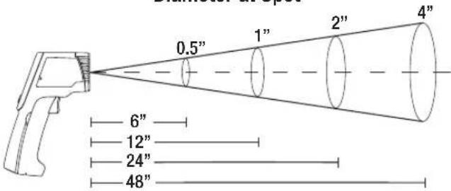
Diameter at Spot
Distance to Object
BATTERY REPLACEMENT
- Open the battery compartment by pulling the compartment lid at the indentations, away from the trigger (see Thermometer Attributes section).
- Remove and recycle exhausted batteries.
- Replace 2 × AAA alkaline batteries observing the polarity indicated on the inside markings.
- Return compartment lid and make sure it locks into place.
GR
GR
PA
WARRANTY
This product is warranted to be free from defects in materials and workmanship for a period of two years from the date of purchase. During this warranty period, Klein Tools has the option to repair or replace or refund the purchase price of any unit which fails to conform to this warranty under normal use and service. This warranty does not cover damage which occurs in shipment or failure which results from alteration, tampering, accident, misuse, abuse, neglect, or improper maintenance. Batteries and damage resulting from failed batteries are not covered by warranty. A purchase receipt or other proof of original purchase date will be required before warranty repairs will be rendered.
Any implied warranties, including but not limited to implied warranties of merchantability and fitness for a particular purpose, are limited to the express warranty. Klein Tools shall not be liable for loss of use of the instrument or other incidental or consequential damages, expenses, or economic loss, or for any claim or claims for such damage, expenses or economic loss.
Some states or countries laws vary, so the above limitations or exclusions may not apply to you. This warranty gives you specific legal rights, and you may also have other rights which vary from state to state. If your Klein product requires repair or for information on how to exercise your rights under the terms of this warranty, please contact Klein Tools at 1-877-775-5346.
CLEANING
Clean the instrument by using a damp cloth. Do not use abrasive cleaners or solvents.
Take care to keep the sensor lens clean at all times. Clean the lens using a soft cloth or cotton swab with water or rubbing alcohol only, and allow the lens to dry before use.
STORAGE
Remove the batteries when instrument is not in use for a prolonged period of time. Do not expose to high temperatures or humidity. After a period of storage in extreme conditions exceeding the limits mentioned in the Specifications section, allow the instrument to return to normal operating conditions before using it.
DISPOSAL/RECYCLE

Caution: This symbol indicates that equipment and its accessories shall be subject to a separate collection and correct disposal.
CUSTOMER SERVICE
KLEIN TOOLS, INC.
450 Bond Street
Lincolnshire, IL 60069
1-877-775-5346
www.kleintools.com

GRAPHICS DRAWING NAME:
GRAPHICS PART NUMBER:
PACKAGING DWG. REF.: NA
IR2000-139672TART
139672T ECN NUMBER.: 10943
Revision: A
Manual de Instrukiones IR2000
ESPANOL
INTERVALO DE MEDICIONDE -76^1022^
RELACION DE pUNTO 12:1
ENFOQUE CON LÁSER DUAL
- MAX/MIN/pROM (AVG)/DIF
PANTALLA CON LUZ DE FONDO
AUTOApAGADO
ALARMA DETEMPERATURA ALTA/BAJA
AUTOESCANEADO
ENTRADA DE TERMOPAR


KLEIN TOOLS
www.kleintools.com
para professionnelles... Entre 1857
ESPANOL
GRAPHICS DRAWING NAME: GRAPHICS PART NUMBER: PACKAGING DWG. REF.: NA
IR2000-139674TART 139674TECN NUMBER:109 Revision:A

GRAPHICS DRAWING NAME:
GRAPHICS PART NUMBER:
PACKAGING DWG. REF.: NA
IR2000-139674TART
139674T ECN NUMBER.:
Revision: A
10!
Mode d'Emploi
IR2000
FRANÇAIS
-76° A 1022° F PLAGE DE MESURE
12:1 RAPPORT OPTIQUE
CIBLAGE LASER DOUBLE
MAX/MIN/DIFF/ MOYENNE
ÉCRAN RÉTROÉCLAIRE
FERMETURE AUTOMATIQUE
ALARME HAUT/BAS
AUTO-SCAN
ENTREE DU THERMOCOUPLE
- Compartment des piles:
GRAPHICS DRAWING NAME
GRAPHICS PART NUMBER:
PACKAGING DWG. REF.: NA