
KINAX N702INOX - Tilt sensor Camille Bauer - Free user manual and instructions
Find the device manual for free KINAX N702INOX Camille Bauer in PDF.
| Product type | Absolute inclination sensor |
| Brand | Camille Bauer |
| Model | KINAX N702 INOX |
| Measuring principle | Magnetic, Hall sensor, oil-damped pendulum system |
| Measuring range | 0 ... 360° (programmable) |
| Output | 4 ... 20 mA, 2-wire technology, reverse polarity protection |
| Supply voltage | 8 ... 33 V DC |
| Current consumption | < 22 mA |
| Accuracy | < ±0.2° (at +25°C) |
| Resolution | 12 bits |
| Housing material | Stainless steel AISI 316Ti (1.4571) |
| Protection rating | IP68 (30 m water column) and IP69K |
| Weight | 1.1 kg |
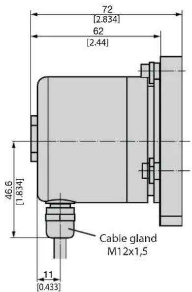
| Electrical connection | 4-wire shielded cable, very flexible |
| Available cable length | 1.5 m to 30 m (depending on version) |
| Operating temperature | -30°C to +70°C |
| Relative humidity | ≤ 100% |
| Vibration resistance | ≤ 40 m/s² / 10 ... 500 Hz (EN 60068-2-6) |
| Shock resistance | 300 m/s² / 18 ms (IEC 60068-2-27) |
| Mounting position | Perpendicular to the measurement object |
| Special functions | Free parameterization via cable (programming of limit stops and rotation direction) |
| Maintenance | No maintenance required |
| Repairs | Exclusively by the manufacturer |
| Included accessories | Mounting plate with 3 clamping brackets |
Frequently Asked Questions - KINAX N702INOX Camille Bauer
User questions about KINAX N702INOX Camille Bauer
0 question about this device. Answer the ones you know or ask your own.
Ask a new question about this device
Download the instructions for your Tilt sensor in PDF format for free! Find your manual KINAX N702INOX - Camille Bauer and take your electronic device back in hand. On this page are published all the documents necessary for the use of your device. KINAX N702INOX by Camille Bauer.
USER MANUAL KINAX N702INOX Camille Bauer
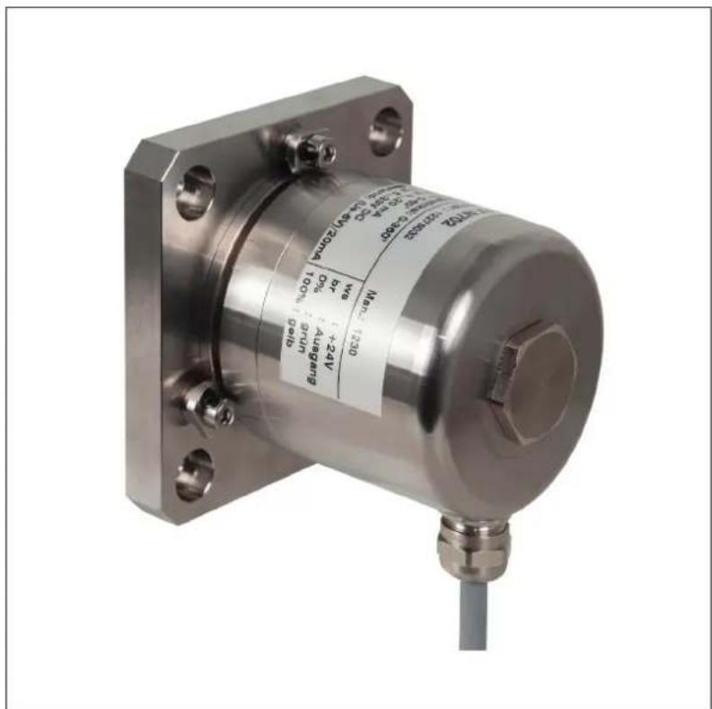
Operating Instructions KINAX N702-INOX Absolute inclination transmitter with oil-damped pendulum system
N702-INOXBdfe 172635-0408.20PM100072600003
Camille Bauer Metrawatt AG
Aargauerstrasse 7
CH-5610 Wohlen/Switzerland
Phone+41566182111
Fax +41 56 618 21 21
info@cbmag.com
www.camillebauer.com
blanc (bc) = + 2 4 V
brun (br) = 4 ... 2 0 mA
vert (ve) = 100 %
jaune (ja) = 0 %
Programmer 0% = 4 mA
1. Safety instructions
1.1 Symbols
The symbols in these instructions point out risks and have the following meaning:

Warning in case of risks.
Non-observance can result in malfunctioning.
Non-observance can result in malfunctioning and personal injury.

Information on proper product handling.
1.4 Repair work and modifications

Repair work and modifications shall exclusively be carried out by the manufacturer. Do not open the housing of the device. In case of any tampering with the device, the guaranty claim shall lapse. We reserve the right of changing the product to improve it.
1.5 Disposal
The disposal of devices and components may only be realised in accordance with good professional practice observing the country-specific regulations.
1.6 Transport and storage

Transport and store the devices exclusively in their original packaging. Do not drop devices or expose them to substantial shocks.
1.2 Intended use
- The KINAX N702-INOX inclination transmitter is a precision instrument. It serves the acquisition of inclination and angular position, processing and the provision of measured values as electric output signals for the downstream device. Use the transmitter for this purpose only.
- The device is intended for installation in industrial plants and meets the requirements of EN 61 010-1.
- Manufacturer is not liable for any damage caused by inappropriate handling, modification or any application not according to the intended purpose.
1.3 Commissioning

- Installation, assembly, setup and commissioning of the device has to be carried out exclusively by skilled workers.
- Observe manufacturer's operating instructions.
- Check all electric connections prior to commissioning the plant.
If assembly, electric connection or other work on the device and the plant are not carried out properly, this may result in malfunctioning or breakdown of the device. - Safety measures should be taken to avoid any danger to persons, any damage of the plant and any damage of the equipment due to breakdown or malfunctioning of the device.
- Do not operate the device outside of the limit values stated in the operating instructions.
2. Scope of delivery
1 Inclination transmitter KINAX N702-INOX
1 Mounting plate with 3 clamps
1 Operating instructions German, English, French
3. Application
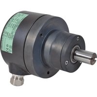
The KINAX N702-INOX is a very robust, absolute inclination transmitter. It is particularly suited for harsh environments due to it ist high mechanical strength and the hermetically sealed stainless steel housing. It makes it resistant against aggressive media such as sea water and detergent.
The very simple assembly by the synchro flange or mounting plate, the highly flexible 4-pole control line, the free parameterisation via the control line offers maximum installation flexibility.
4. Main features
- Robust inclination transmitter suitable for field applications
Hermetically sealed stainless-steel INOX AiSi 316Ti (1.4571) housing with a protection class of IP68 and IP69K - Resistant to aggressive media such as sea water and detergent
- Steadfast to high mechanical loads
- Free parameterization via control line
5. Technical data
5.1 General
Measured quantity: Tilt angle
Measuring principle: Magnetic, one-dimensional inclination transmitter with hall sensor and oil-damped pendulum system, hermetically sealed, contact free, freely rotatable without stops
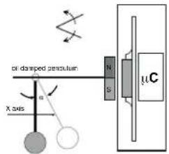
Pendulum damping: by oil filling
5.2 Measuring input
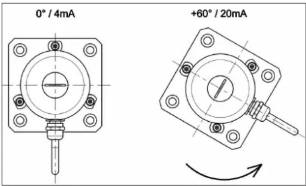
Measuring range: Programmable between 0 ... 360°
Inclination angle: Set to 0 ... 359.9°
Sense of rotation: Adjustable for rotation clockwise or counter-clockwise
5.3 Measuring output
Power supply: 8 ... 33 VDC
Output signal IA : Load-independent DC current, proportional to the inclination
Current consumption: < 22mA
Standard range: 4...20 mA, 2-wire connection protection against wrong polarity
External resistance: R H[V] - 8V/IA[mA]
H = Power supply IA = Output signal end value
5.4 Accuracy
Basic accuracy: < ± 0.2° (at +25 °C)
Resolution: 12 bit
Transient response: by 25° tils < 1 sec.
Influence of temperature output current
(-30°... +70°C) ± 0,1° / 10K (>100°)
[-22...+158°F]
5.5 Installation data
Housing: Stainless-steel INOX AiSi 316Ti (1.4571)
Mounting position: Perpendicular to the measurement object
Electrical connection: highly flexible shielded 5-pin control cable
Weight: 1.1 kg [35.366 oz]
5.6 Regulations
Spurious radiation: EN 61 000-6-3
Immunity: EN 61000-6-2
Test voltage: 500 Veff, 50 Hz, 1 min.
Housing protection: IP 68 acc. to EN 60 529
IP 69k acc. to EN 40 050-9
water column: 30 m
5.7 Environmental condition
Climatic rating: Temperature - 30° to + 70°C [-22 ... +158 °F]
Relative humidity < 100%
Vibration resistance: ≤ 40m / s2 / 10... 500Hz
acc.IEC 60068-2-6
Shock resistance: 300m / s2 /18ms
acc.IEC 60068-2-27
Transportation and
storage temperature: -30° to +70°C [-22...+158°F]
5.8 Dimensional drawings
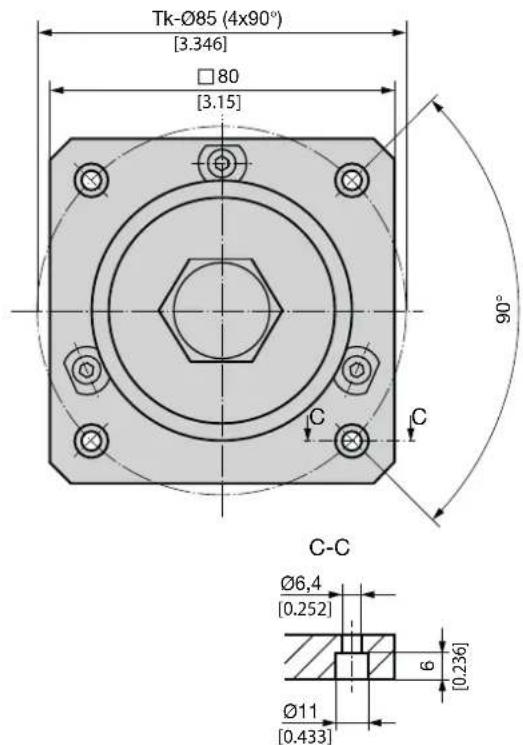
6. Mounting
All inclination transmitter can be mounted either directly with 3 clamping brackets to the item being measured or with a mounting plate with 4 cheese head screws M6. Please take care that the installation position of the inclination transmitter is perpendicular to the gravity of the earth. The inclination transmitter are supplied standard with mounting plate but without cheese head screws M6.

- Avoid impacts or shocks on the housing.
- Do not deform housing.
- Do not open or mechanically modify the device.
| Mounting versions Drilling aund cut-out diagrams (for mounting transmitters) | ||
| directly with clamps | 066.2 [2.606] M4 50° 130° | |
| with mounting plate | 60.1 2.366 601 2.366 M6 | |
7. Electric connections
The inclination sensor is connected via a highly flexible, shielded control lead with 4 strands. The same is preassembled at the factory, included in the delivery and available in different lengths.
- Do not electricly modify the device nor carry out any wiring work when energised.
- Do not plug in or unplug electric connection when energised.
conductor cross-section: 4 × 0.25 mm
wiring connection
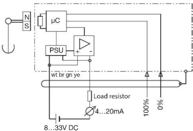
White (wt) = + 2 4 V Brown (br) = 4 ... 2 0 mA Green (gn) = 100 % Yellow(ye) = 0%
8. Electric commissioning
- Provide a separate power supply for the device in case of consumer loads with high interference levels.
- Install the entire plant in an EMC-compatible manner. Installation environment and wiring can affect the EMC of the device.
9. Maintenance
The device is free of maintenance. Repairs may only be carried out by authorized authorities.
10. Programming instruction
The inclination transmitter is programmable via the connecting cable. To program the strands please use the green and the yellow wire. It can be programmed the start value (0%) , the end value (100%) and the sense of rotation.

- A reset to factory settings is not possible.
- The inclination transmitter must be connected according to the wiring diagram (see page 13)
- Clockwise rotation corresponds to the counter-clockwise (top view cap) with increasing output signal.
Application: The measuring range (e.g. 4 - 20mA ) is between two fixed tilt angles (e.g. 0° to +60° ). By shortly contacting the programming lines to the supply voltage, the end position can be adjusted after mounting the inclination transmitter on an aligned target. The orientation of the outgoing line can be chosen freely.
- Put transmitter into initial position
program 0% = 4mA
1x short contact* of yellow with white (+24 V)
- Put transmitter into final position
program 100% = 20mA
1x short contact* of green with white (+24 V)
- Switch sense of rotation (optional)
1x short contact* of yellow and green with white (+24 V)
-
On safety reason place after programming the yellow and green wire on brown wire (0V)
-
short contact = 50 ... 500 ms
11. Ordering information of variants
| Description Article No. | |
| KINAX N702-INOX, Cable length 1,5 m 172 479 | |
| KINAX N702-INOX, Cable length 3,0 m 172 487 | |
| KINAX N702-INOX, Cable length 5,0 m 172 495 | |
| KINAX N702-INOX, Cable length 10,0 m 172 502 | |
| KINAX N702-INOX, Cable length 15,0 m 186 107 | |
| KINAX N702-INOX, Cable length 20,0 m 173 097 | |
| KINAX N702-INOX, Cable length 30,0 m 172 528 | |
| Further cable lengths on request xxx xxx |
12. Accessories
| Description Article No. | |
| Mounting plate N7xx INOX 172 619 | |
| Kit mounting clamp N7xx INOX 172 627 |

- SAFETY INSTRUCTIONS
- 1.1 SYMBOLS
- 1.2 INTENDED USE
- 1.3 COMMISSIONING
- SCOPE OF DELIVERY
- APPLICATION
- MAIN FEATURES
- TECHNICAL DATA
- 5.1 GENERAL
- 5.2 MEASURING INPUT
- 5.3 MEASURING OUTPUT
- 5.4 ACCURACY
- 5.5 INSTALLATION DATA
- 5.6 REGULATIONS
- 5.7 ENVIRONMENTAL CONDITION
- 5.8 DIMENSIONAL DRAWINGS
- MOUNTING
- ELECTRIC CONNECTIONS
- ELECTRIC COMMISSIONING
- MAINTENANCE
- PROGRAMMING INSTRUCTION
- ORDERING INFORMATION OF VARIANTS
- ACCESSORIES
Brand : Camille Bauer
Model : KINAX N702INOX
Category : Tilt sensor