W6VB3 - Drill METABO - Free user manual and instructions
Find the device manual for free W6VB3 METABO in PDF.
User questions about W6VB3 METABO
0 question about this device. Answer the ones you know or ask your own.
Ask a new question about this device
Download the instructions for your Drill in PDF format for free! Find your manual W6VB3 - METABO and take your electronic device back in hand. On this page are published all the documents necessary for the use of your device. W6VB3 by METABO.
USER MANUAL W6VB3 METABO
INSTRUCTION MANUAL AND SAFETY INSTRUCTIONS
WARNING
Improper and unsafe use of this power tool can result in death or serious bodily injury!
This manual contains important information about product safety. Please read and understand this manual before operating the power tool. Please keep this manual available for others before they use the power tool.
MODE D'EMPLOI ET INSTRUCTIONS DE SECURITE
AVENTISSEMENT
APPLICATIONS 8
PRIOR TO OPERATION 8
HOW TO USE THE SCREW DRIVER ... 10
MOUNTING AND DISmountING
THE HEX-SOCKET OR BIT 11
MAINTENANCE AND INSPECTION .... 12
ACCESSIONS 13
STANDARD ACCESSORIES 13
OPTIONAL ACCESSORIES 14
PART LIST 40
TABLE DES MATIERES
Français
Page
Page
INFORMATIONS IMPORTANTES DE SECURITE ... 15
SIGNIFICATION DES MOTS D'AVERTISSEMENT .... 15
SECURITE 15
AVERTISSEMENTS DE SECURITE GENERAUX
CONCERNANT LES OUTILS ELECTRIQUES 15
REGLES DE SECURITE SPECIFIQUES ET SYMBOLES .... 17
DOUBLE ISOLATION POUR UN
FONCTIONNEMENT PLUS SUR ... 18
DESCRIPTION FONCTIONNELLE 19
NOM DES PARTIES 19
SPECIFICATIONS 19
ASSEMBLAGE ET FONCTIONNEMENT .... 20
APPLICATIONS 20
ACCESSIONS STANDARD 25
ACCESSOIRESRUPOPTION 26
LISTEDESPIECES 40
INDICE
Espanol
Página
Pagina
INFORMATION IMPORTANTE SOBRE SEGURIDAD ... 27
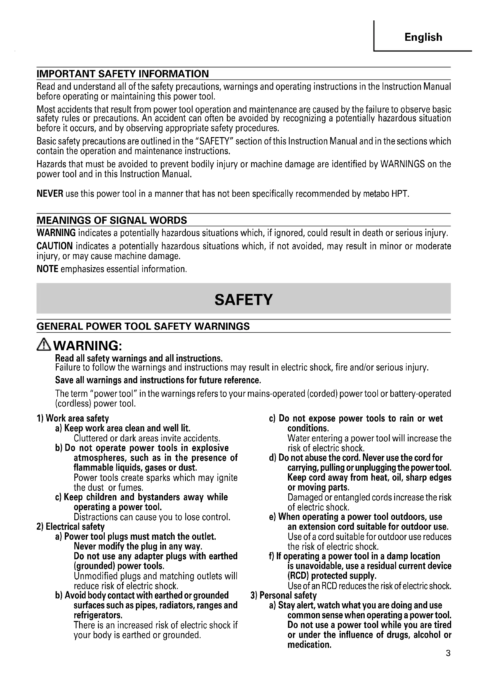
IMPORTANT SAFETY INFORMATION
Read and understand all of the safety precautions, warnings and operating instructions in the Instruction Manual before operating or maintaining this power tool.
Most accidents that result from power tool operation and maintenance are caused by the failure to observe basic safety rules or precautions. An accident can often be avoided by recognizing a potentially hazardous situation before it occurs, and by observing appropriate safety procedures.
Basic safety precautions are outlined in the "SAFETY" section of this Instruction Manual and in the sections which contain the operation and maintenance instructions.
Hazards that must be avoided to prevent bodily injury or machine damage are identified by WARNINGS on the power tool and in this Instruction Manual.
NEVER use this power tool in a manner that has not been specifically recommended by metabo HPT.
MEANINGS OF SIGNAL WORDS
WARNING indicates a potentially hazardous situations which, if ignored, could result in death or serious injury.
CAUTION indicates a potentially hazardous situations which, if not avoided, may result in minor or moderate injury, or may cause machine damage.
NOTE emphasizes essential information.
SAFETY
GENERAL POWER TOOL SAFETY WARNINGS
WARNING:
Read all safety warnings and all instructions.
Failure to follow the warnings and instructions may result in electric shock, fire and/or serious injury.
Save all warnings and instructions for future reference.
The term "power tool" in the warnings refers to your mains-operated (corded) power tool or battery-operated (cordless) power tool.
1) Work area safety
a) Keep work area clean and well lit.
Cluttered or dark areas invite accidents.
b) Do not operate power tools in explosive atmospheres, such as in the presence of flammable liquids, gases or dust.
Power tools create sparks which may ignite the dust or fumes.
c) Keep children and bystanders away while operating a power tool.
Distractions can cause you to lose control.
2) Electrical safety
a) Power tool plugs must match the outlet.
Never modify the plug in any way.
Do not use any adapter plugs with earthed (grounded) power tools.
Unmodified plugs and matching outlets will reduce risk of electric shock.
b) Avoid body contact with earthed or grounded surfaces such as pipes, radiators, ranges and refrigerators.
There is an increased risk of electric shock if your body is earthed or grounded.
c) Do not expose power tools to rain or wet conditions.
Water entering a power tool will increase the risk of electric shock.
d) Do not abuse the cord. Never use the cord for carrying, pulling or unplugging the power tool. Keep cord away from heat, oil, sharp edges or moving parts.
Damaged or entangled cords increase the risk of electric shock.
e) When operating a power tool outdoors, use an extension cord suitable for outdoor use.
Use of a cord suitable for outdoor use reduces the risk of electric shock.
f) If operating a power tool in a damp location is unavoidable, use a residual current device (RCD) protected supply.
Use of an RCD reduces the risk of electric shock.
3) Personal safety
a) Stay alert, watch what you are doing and use common sense when operating a power tool. Do not use a power tool while you are tired or under the influence of drugs, alcohol or medication.
A moment of inattention while operating power tools may result in serious personal injury.
b) Use personal protective equipment. Always wear eye protection.
Protective equipment such as dust mask, nonskid safety shoes, hard hat, or hearing protection used for appropriate conditions will reduce personal injuries.
c) Prevent unintentional starting. Ensure the switch is in the off-position before connecting to power source and/or battery pack, picking up or carrying the tool.
Carrying power tools with your finger on the switch or energising power tools that have the switch on invites accidents.
d) Remove any adjusting key or wrench before turning the power tool on.
A wrench or a key left attached to a rotating part of the power tool may result in personal injury.
e) Do not overreach. Keep proper footing and balance at all times.
This enables better control of the power tool in unexpected situations.
f) Dress properly. Do not wear loose clothing or jewellery. Keep your hair, clothing and gloves away from moving parts.
Loose clothes, jewellery or long hair can be caught in moving parts.
g) If devices are provided for the connection of dust extraction and collection facilities, ensure these are connected and properly used.
Use of dust collection can reduce dust-related hazards.
4) Power tool use and care
a) Do not force the power tool. Use the correct power tool for your application.
The correct power tool will do the job better and safer at the rate for which it was designed.
b) Do not use the power tool if the switch does not turn it on and off.
Any power tool that cannot be controlled with the switch is dangerous and must be repaired.
c) Disconnect the plug from the power source and/or the battery pack from the power tool before making any adjustments, changing accessories, or storing power tools.
Such preventive safety measures reduce the risk of starting the power tool accidentally.
d) Store idle power tools out of the reach of children and do not allow persons unfamiliar with the power tool or these instructions to operate the power tool.
Power tools are dangerous in the hands of untrained users.
e) Maintain power tools. Check for misalignment or binding of moving parts, breakage of parts and any other condition that may affect the power tool's operation.
If damaged, have the power tool repaired before use.
Many accidents are caused by poorly maintained power tools.
f) Keep cutting tools sharp and clean.
Properly maintained cutting tools with sharp cutting edges are less likely to bind and are easier to control.
g) Use the power tool, accessories and tool bits etc. in accordance with these instructions, taking into account the working conditions and the work to be performed.
Use of the power tool for operations different from those intended could result in a hazardous situation.
5) Service
a) Have your power tool serviced by a qualified repair person using only identical replacement parts.
This will ensure that the safety of the power tool is maintained.
SPECIFIC SAFETY RULES AND SYMBOLS
- Wear ear protectors.

Exposure to noise can cause hearing loss.
- Hold power tools by insulated gripping surfaces, when performing an operation where the fastener may contact hidden wiring or its own cord.
Fasteners contacting a "live" wire may make exposed metal parts of the power tool "live" and could give the operator an electric shock.
-
Employ a driver bit appropriate for the screw diameter.
-
Apply the screw driver body perpendicularly to a screw head when driving a screw.
-
NEVER touch the tool bit with bare hands after operation.
-
NEVER wear gloves made from materials likely to roll up such as cotton, wool, cloth or string, etc.
-
NEVER touch moving parts.
NEVER place your hands, fingers or other body parts near the tool's moving parts.
- NEVER operate without all guards in place.
NEVER operate this tool without all guards or safety features in place and in proper working order. If maintenance or servicing requires the removal of a guard or safety feature, be sure to replace the guard or safety feature before resuming operation of the tool.
- Use right tool.
Don't force small tool or attachment to do the job of a heavy-duty tool.
Don't use tool for purpose not intended -for example-don't use circular saw for cutting tree limbs or logs.
- NEVER use a power tool for applications other than those specified.
NEVER use a power tool for applications other than those specified in the Instruction Manual.
- Handle tool correctly.
Operate the tool according to the instructions provided herein. Do not drop or throw the tool.
NEVER allow the tool to be operated by children, individuals unfamiliar with its operation or unauthorized personnel.
- Keep all screws, bolts and covers tightly in place.
Keep all screws, bolts, and plates tightly mounted. Check their condition periodically.
- Do not use power tools if the plastic housing or handle is cracked.
Cracks in the tool's housing or handle can lead to electric shock. Such tools should not be used until repaired.
- Blades and accessories must be securely mounted to the tool.
Prevent potential injuries to yourself or others. Blades, cutting implements and accessories which have been mounted to the tool should be secure and tight.
- Keep motor air vent clean.
The tool's motor air vent must be kept clean so that air can freely flow at all times. Check for dust build-up frequently.
- Operate power tools at the rated voltage.
Operate the power tool at voltages specified on its nameplate.
If using the power tool at a higher voltage than the rated voltage, it will result in abnormally fast motor revolution and may damage the unit and the motor may burn out.
- NEVER use a tool which is defective or operating abnormally.
If the tool appears to be operating unusually, making strange noises, or otherwise appears defective, stop using it immediately and arrange for repairs by a metabo HPT authorized service center.
- NEVER leave tool running unattended. Turn power off.
Don't leave tool until it comes to a complete stop.
- Carefully handle power tools.
Should a power tool be dropped or struck against hard materials inadvertently, it may be deformed, cracked, or damaged.
- Do not wipe plastic parts with solvent.
Solvents such as gasoline, thinner benzine, carbon tetrachloride, and alcohol may damage and crack plastic parts. Do not wipe them with such solvents.
Wipe plastic parts with a soft cloth lightly dampened with soapy water and dry thoroughly.
-
ALWAYS wear eye protection that meets the requirement of the latest revision of ANSI Standard Z87.1.
-
When working in high places, check there is nobody below. During operation, take care not to catch or tighten the cord accidentally.
-
Switch the reversing switch only after the motor is stopped when it is necessary to change the direction of the rotation.
-
Use a step up transformer when a long extension cable is used.
-
Confirm the tightening torque by a torque wrench before use in order to ascertain the correct tightening torque to be used.
-
Attach the hex. socket securely onto the anvil. If the hex. socket is insufficiently secured, it may drop out and cause an accident. For hex. socket attachment refer to "PRIOR TO OPERATION" on page 8.
-
Confirm whether the socket has any crack in it.
-
Definitions for symbols used on this tool
V..... volts
Hz ......... hertz
A . amperes
no no load speed
W...watt
Class II Construction
---/min .... revolutions per minute
Alternating current
To ensure safer operation of this power tool, metabo HPT has adopted a double insulation design. "Double insulation" means that two physically separated insulation systems have been used to insulate the electrically conductive materials connected to the power supply from the outer frame handled by the operator. Therefore, either the symbol "□" or the words "Double insulation" appear on the power tool or on the nameplate. Although this system has no external grounding, you must still follow the normal electrical safety precautions given in this Instruction Manual, including not using the power tool in wet environments.
To keep the double insulation system effective, follow these precautions:
Only metabo HPT AUTHORIZATION SERVICE CENTER should disassemble or assemble this power tool, and only genuine metabo HPT replacement parts should be installed.
Clean the exterior of the power tool only with a soft cloth moistened with soapy water, and dry thoroughly.
Never use solvents, gasoline or thinners on plastic components; otherwise the plastic may dissolve.
SAVE THESE INSTRUCTIONS
AND
MAKE THEM AVAILABLE TO
OTHER USERS
AND
OWNERS OF THIS TOOL!
FUNCTIONAL DESCRIPTION
NOTE:
The information contained in this Instruction Manual is designed to assist you in the safe operation and maintenance of the power tool.
NEVER operate, or attempt any maintenance on the tool unless you have first read and understood all safey instructions contained in this manual.
Some illustrations in this Instruction Manual may show details or attachments that differ from those on your own power tool.
NAME OF PARTS
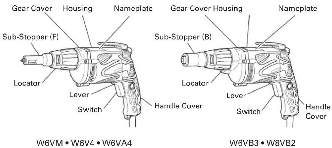
Fig. 1
SPECIFICATIONS
| Model W6VM W6V4 W6VA4 W6VB3 W8VB2 | |||||
| Motor Single-Phase, Series Commutator Motor | |||||
| Power Source Single-Phase, 120 V 60 Hz | |||||
| Current 6.6 A | |||||
| No-Load Speed | 0-6000/min | 0-4500/min 0-3000/min 0-2600/min 0-1700/min | |||
| Capacity | Drywall screw | 3/16" (5 mm) | 1/4" (6 mm) | ||
| Self-drilling screw | 1/4" (6 mm) | 5/16" (8 mm) | |||
| Weight 3.1 lbs (1.4 kg) | 3.3 lbs (1.5 kg) | ||||
ASSEMBLY AND OPERATION
APPLICATIONS
Tightening hex. head screws
O Tightening Drywall screws, wood screws and self-drilling screws
NOTE:
For tightening the Self-drilling screws, sub-stopper (B) and non-magnetic bit holder (sold separately) are recommended.
PRIORTO OPERATION
1.Power source
Ensure that the power source to be utilized conforms to the power source requirements specified on the product nameplate.
2. Power switch
Ensure that the switch is in the OFF position. If the plug is connected to a receptacle while the switch is in the ON position, the power tool will start operating immediately and can cause serious injury.
3. Extension cord
When the work area is far away from the power source, use an extension cord of sufficient thickness and rated capacity. The extension cord should be kept as short as practicable.

WARNING:
Damaged cord must be replaced or repaired.
4. Check the receptacle
If the receptacle only loosely accepts the plug, the receptacle must be repaired.
Contact a licensed electrician to make appropriate repairs.
If such a faintly receptacle is used, it may cause overheating, resulting in a serious hazard.
5. Confirming condition of the environment
Confirm that the work site is placed under appropriate conditions conforming to prescribed precautions.
6. Confirm the direction of bit rotation (Fig. 2)
The bit rotates clockwise (viewed from the rear side) when the reversing switch lever is set to the "R" side position. When the lever is set to the "L" side position, the bit rotates counterclockwise and can be used to loosen and remove screws.
CAUTION:
Never change the bit rotating direction while operating the Screw Driver. Turn the main switch off before changing the rotating direction, otherwise, burning of the motor will result.
7Adjusting the tightening depth (Fig. 3)
The tightening depth can be adjusted by turning locator right and left with click feeling.
(1) For hex-head screws (Fig. 4)
Mount a hex-head screw on the hex-socket and set the distance between the sub-stopper end and the screw head neck to 0.04^ - 0.06^ (1 - 1.5 mm).
(2) For drywall screws (Fig. 5)
Mount a drywall screw on the bit, and set the distance between the sub-stopper end and the screw head to 0.06^ - 0.07^ (1.5 - 2 mm).
(3) For cross-recessed self-drilling screws (Fig. 6)
Mount a self-drilling screw on the bit, and set the distance between the substopper end and the screw head bottom to 0.04'' - 0.06'' (1 - 1.5 mm).
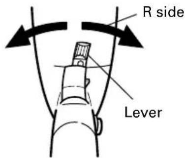
Fig. 2
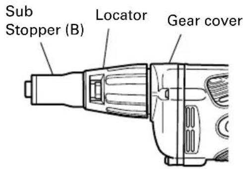
Fig. 3
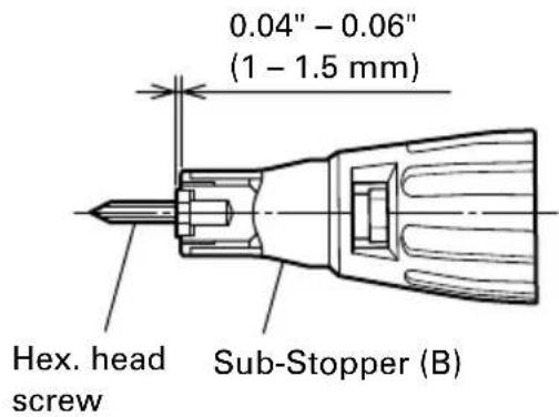
Fig. 4
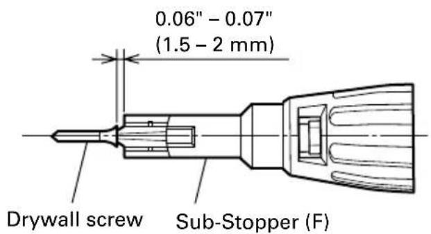
Fig. 5
8. Mounting the bit
For details, refer to the item "Mounting and dismounting the hex-socket or the bit".
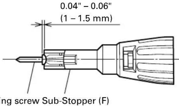
Fig. 6
HOW TO USE THE SCREW DRIVER
1. Switch operation and rotational speed adjustment
Bit rotational speed can be adjusted between 0-6000/min (W6VM) or 0-4500/min (W6V4) or 0-3000/min (W6VA4) or 0-2600/min (W6VB3) or 0-1700/min (W8VB2) varying the degree by which the trigger switch is pulled. Rotational speed increases as the trigger switch is pulled, and reaches a maximum speed of 6000/min (W6VM) or 4500/min (W6V4) or 3000/min (W6VA4) or 2600/min (W6VB3) or 1700/min (W8VB2) when the trigger switch is pulled fully.
To facilitate continuous operation, pull the trigger switch and depress the switch stopper. The switch will then remain ON even when the finger is released. By pulling the trigger switch again, the switch stopper disengages and the switch is turned OFF when the trigger switch is released.
2. Screw Driver operation
When the switch is turned ON, the motor starts to run but the hex-socket (or the bit) does not rotate. Attach the hex-socket to the screw head groove, and push the Screw Driver against the screw. The hex-socket then rotates and tightens the screw.
CAUTION
Ensure that the Screw Driver is held truly perpendicular to the head of the screw. If held at an angle, the driving force will not be fully transferred to the screw, and the screw head and/or hex-socket will be damaged. Hex-socket rotation stops when pushing force is released.
3. Direction of hex-socket rotation
The hex-socket rotates clockwise (viewed from the rear side) when the reversing switch lever is set to the "R" side position. When the lever is set to the "L" side position, the hex-socket rotates counterclockwise, and can be used to loosen and remove screws.
CAUTION
Never change the direction of hex-socket (or bit holder) rotation while the motor is running. To do so would seriously damage the motor. Turn the power switch OFF before changing the direction of hex-socket (or bit holder) rotation.
- Tightening Self-drilling screw
When the supplied magnet bit holder is used to tighten the Self-drilling screw into a steel plate, cut material stuck in the magnet bit will degrade the work efficiency.
To prevent this, the non-magnetic bit holder (optional accessory) is recommended. The stainless locator with bushing (optional accessory) will prevent the bushing from being worn.
MOUNTING AND DISmountING THE HEX-SOCKET OR THE BIT
CAUTION
Be sure to switch power OFF and disconnect the plug from receptacle to avoid serious trouble.
- Dismounting the hex-socket (Fig. 7)
(1) While rotating the Sub-Stopper pull it out from the locator.
(2) Remove the hex-socket, hold it with the opposite side of bit by hand or vise and pull out the bit with pliers. - Dismounting the bit (Fig. 8)
Remove sub-stopper (G) as the same manner of hex-head socket and remove the bit holder, then pull out the bit with pliers.
- Dismounting the bit (Fig. 9)
Remove the sub-stopper (F) as the same manner of hex-head socket and remove the bit holder, then pull out the bit with pliers.
- Mounting the hex-socket or the bit Install the bit in the reverse order to removal.
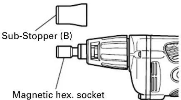
Fig. 7
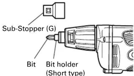
Fig. 8
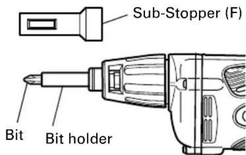
Fig. 9
MAINTENANCE AND INSPECTION
WARNING: Be sure to switch power OFF and disconnect the plug from the receptacle during maintenance and inspection.
1.Inspecting the hex. socket (or bit)
Since continued use of a worn hex. socket (bit) will damage screw heads, replace the hex. socket (bit) with a new one as soon as excessive wear is noticed.
- Inspecting the screws
Regularly inspect all screws and ensure that they are properly tightened. Should any of the screws be loosened, retighten them immediately.
WARNING: Using this screw driver with loosened screws is extremely dangerous.
- Maintenance of the motor
The motor unit winding is the very "heart" of the power tool. Exercise due care to ensure the winding does not become damaged and/or wet with oil or water.
- Cleaning the unit exterior
Wipe off oil and stain on the unit exterior with a dried rag or a rag moistened with soapy water.
- Inspecting the carbon brushes
For your continued safety and electrical shock protection, carbon brush inspection and replacement on this tool should ONLY be performed by a metaboHPT Authorized Service Center.
- Service and repairs
All quality power tools will eventually require servicing or replacement of parts because of wear from normal use. To assure that only authorized replacement parts will be used, all service and repairs must be performed by a metaboHPT Authorized Service Center, ONLY.
- Service parts list
A: Item No.
B:Code No.
C: No. Used
D: Remarks
CAUTION: Repair, modification and inspection of metabo HPT Power Tools must be carried out by a metabo HPT Authorized Service Center.
This Parts List will be helpful if presented with the tool to the metaboHPT Authorized Service Center when requesting repair or other maintenance. In the operation and maintenance of power tools, the safety regulations and standards prescribed in each country must be observed.
MODIFICATIONS:
metabo HPT Power Tools are constantly being improved and modified to incorporate the latest technological advancements.
Accordingly, some parts (i.e. code numbers and/or design) may be changed without prior notice.
ACCESSIONS
WARNING: ALWAYS use Only authorized metabo HPT replacement parts and accessories. NEVER use replacement parts or accessories which are not intended for use with this tool. Contact metabo HPT if you are not sure whether it is safe to use a particular replacement part or accessory with your tool.
The use of any other attachment or accessory can be dangerous and could cause injury or mechanical damage.
NOTE: Accessories are subject to change without any obligation on the part of the metabo HPT.
STANDARD ACCESSORIES
W6VM·W6V4·W6VA4>
(1) No. 2 Phillips driver bit (Code No. 971511Z)
(2) Magnetic bit holder (Code No. 982554Z)
(3) Sub-stopper (F) (Code No. 323351)
W6VB3·W8VB2>
(1) Magnetic hex. socket (H=5/16" (7.94 mm)) (Code No. 985322)
(2) Sub-stopper (B) (H = 5 / 16^ (7.94 mm)) (Code No. 317671)
OPTIONAL ACCESSORIES ......sold separately
1.For hex-head screws
| Hex-socket | Sub-Stopper (B) | ||
| Magnetic type | Non magnetic type | ||
| Size Code No. Size Code No. Size Code No. | |||
| H 1/4 985332 H 1/4 985328 H 1/4 317827 | |||
| H 5/16 985322 H 5/16 | 985327 H 5/16 | 317671 | |
| H 3/8 985330 H 3/8 985326 H 3/8 317670 | |||
2. For other screws
| Screw head | Bit | Bit holder | Sub-Stopper | ||
| Type Size | Code No. | ||||
| ⊕ | No.1 985 | 333 | Magnetic bit holder (Short type) | Sub-Stopper (G) (Code No. 323352) | |
| No.2 971 | 511Z | ||||
| No.3 971 | 512Z | ||||
| No.1 985 | 334 | ||||
| No.2 985 | 335 | ||||
| ∅ | No.1 985 | 336 | Magnetic bit holder (Code No. 982554Z) | Sub-Stopper (F) (Code No. 323351) | |
| No.2 985 | 337 | ||||
| No.3 985 | 338 | ||||
| No.1 985 | 340 | ||||
| No.2 985 | 341 | ||||
| B | B Size 5/32" (4 mm) 13/64" (5 mm) | 985342 | Non-magnetic bit bolder (Code No. 982563Z) | ||
| 985343 | |||||
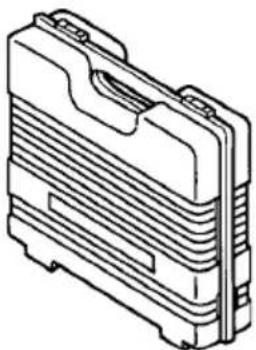
3. Plastic case (Code No. 310504)
NOTE:
Specifications are subject to change without any obligation on the part of the metabo HPT.
INFORMATIONS IMPORTANTES DE SECURITÉ
A: No. élément
B: No. code
C: No. utilise
D: Remarques

Some dust created by power sanding, sawing, grinding, drilling, and other construction activities contains chemicals known to the State of California to cause cancer, birth defects or other reproductive harm. Some examples of these chemicals are:
-Lead from lead-based paints,
- Crystalline silica from bricks and cement and other masonry products, and
- Arsenic and chromium from chemically-treated lumber.
Your risk from these exposures varies, depending on how often you do this type of work. To reduce your exposure to these chemicals: work in a well ventilated area, and work with approved safety equipment, such as those dust masks that are specially designed to filter out microscopic particles.
AVENTISSEMENT:
Minato-ku, Tokyo 108-6020, Japan
Distributed by
Koki Holdings America Ltd.
1111 Broadway Ave,
Braselton, Georgia, 30517
Koki Holdings America Ltd. Canadian Branch
3405 American Drive, Units 9-10
Mississauga, ON, L4V 1T6
Hikoki Power Tools de Mexico S.A. de C.V.
Calle Isaac Newton No.286, 2do Piso, Col. Polanco V Seccion,
Del. Miguel Hidalgo, C.P. 11560
Ciudad de Mexico, Mexico.
806
Code No.C99129965 M
Printed in Malaysia