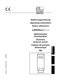
PI2058 - Pressure sensor IFM - Free user manual and instructions
Find the device manual for free PI2058 IFM in PDF.


User questions about PI2058 IFM
0 question about this device. Answer the ones you know or ask your own.
Ask a new question about this device
Download the instructions for your Pressure sensor in PDF format for free! Find your manual PI2058 - IFM and take your electronic device back in hand. On this page are published all the documents necessary for the use of your device. PI2058 by IFM.
USER MANUAL PI2058 IFM
Electronic pressure sensor
Read the product description before installing the unit. Ensure that the product is suitable for your application without any restrictions.
Non-adherence to the operating instructions or technical data can lead to personal injury and/or damage to property.
In all applications check compliance of the product materials (see Technical data) with the media to be measured.
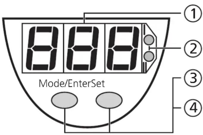
Controls and indicating elements
| ① | 7-segment display | Display of the system pressure1), display of parameters and parameter values. |
| ② | 2 x LED red | Switching status; lights if output I / II has switched. |
| ③ | Mode / Enter button | Selection of the parameters and acknowledgement of the parameter values. |
| ④ | Set button | Setting of the parameter values (scrolling by holding pressed; incremental by pressing briefly). |
Function and features
- The pressure sensor detects the system pressure,
- shows the current system pressure on its display,
- and generates 2 output signals according to the set output configuration.
| Output 1 Output 2 | ||
| Analogue output (only output 2) | I: 4 ... 20 mA | |
| U: 0 ... 10 V | ||
| Switching function (output 1 and output 2; function can be selected for each output separately) | hysteresis function / N.O. (Hno) | |
| hysteresis function / N.C. (Hnc) | ||
| window function / N.O. (Fno) | ||
| window function / N.C. (Fnc) | ||
| Output polarity (applies to both switching outputs) | p-switching (PnP) | |
| n-switching (nPn) | ||
Display range
| mbar | -13 ... 263 |
| inH2O | -5.0 ... 105 |
| kPa | -1.3 ... 26.3 |
Applications
Type of pressure: relative pressure
| Measuring range | Permissible overl. pressure | Bursting pressure | |
| mbar | -13 ... 250 10 000 (10bar) 30 000 (30bar) | ||
| inH2O | -5.0 ... 100 4 000 12 000 | ||
| kPa | -1.3 ... 25.0 1 000 (1MPa) 3 000 (3MPa) |

Avoid static and dynamic overpressure exceeding the given overload pressure.
Even if the bursting pressure is exceeded only for a short time the unit can be destroyed (danger of injuries)!
Operating modes
Run mode
Normal operating mode
At power on the unit is in the Run mode. It carries out its measurement and evaluation functions and provides output signals according to the set parameters.
The display shows the current system pressure (can be deactivated; page 30). The red LEDs indicate the switching state of the outputs.
Display mode
Indication of parameters and the set parameter values
When the "Mode/Enter" button is pressed briefly, the unit passes to the Display mode which allows parameter values to be read. The internal sensing, processing and output functions of the unit continue as if in Run mode.
- The parameter names are scrolled with each pressing of the "Mode/Enter" button.
- When the "Set" button is pressed briefly, the corresponding parameter value is displayed for 15s. After another 15s the unit returns to the Run mode.
Programming mode
Setting of the parameter values
While viewing a parameter value pressing the "Set" button for more than 5s causes the unit to enter the programming mode. You can alter the parameter value by pressing the "Set" button and confirm the new value by pressing the "Mode/Enter" button. The internal sensing, processing and output functions of the unit continue as if in Run mode with the original parameter values unless a new value is confirmed. The unit returns to the Run mode when no button has been pressed for 15s.
Installation

Before mounting and removing the sensor, make sure that no pressure is applied to the system.
Horizontal mounting recommended for high medium temperatures.
The unit is adaptable for various process fittings by Aseptoflex adapters (to be ordered separately as accessories).
Mount adapter (C) to the sensor first, then sensor + adapter to the process connection by means of a nut, a clamping flange or similar (B).
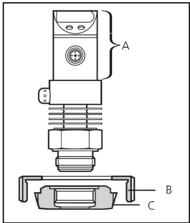
A = freely rotatable housing
If it is not possible to slide the fixing element (B) down over the top of the sensor: slide it up over the bottom of the sensor before the adapter is mounted.
NOTE: A guarantee for a long-term stable and maintenance-free fitting, with no bug traps in the hygienic sealing of the metal seal (Aseptoflex connection) is only valid for once-only mounting.
Welding adapter
If you use a welding adapter: Weld the adapter first. Then mount the sensor.
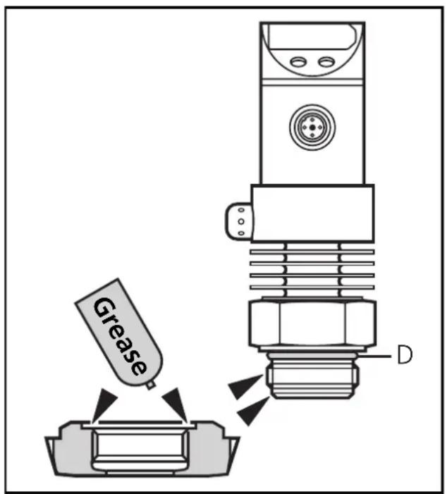
Mounting of the Aseptoflex adapter Step 1
Grease thread and sealing chamfer of the sensor and of the adapter with the greasing paste supplied.
The greasing paste is food-grade (USDA-H1 84-201).
Make sure that the O-ring (D) is correctly positioned.
Step 2
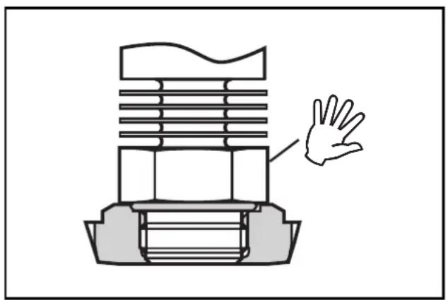
Screw the sensor into the adapter. Avoid mechanical influence on the sealing chamfers.
Step 3
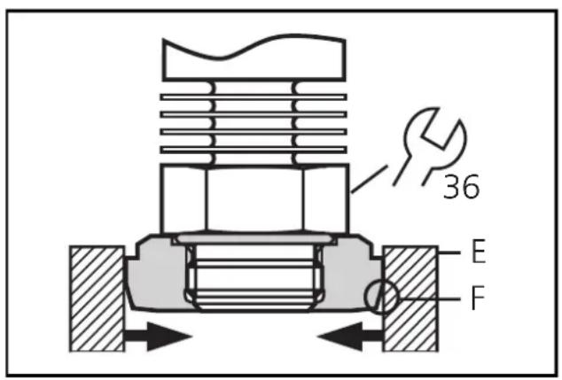
Clamp sensor and adapter into a clamping device (E). The sealing chamfers (F) must not be damaged. Tighten the sensor with a spanner until you can feel the end stop.

If you continue to turn, this can have adverse effect on the sealing.
Electrical connection

The unit must be connected by a suitably qualified electrician.
The national and international regulations for the installation of electrical equipment must be observed.
Voltage supply to EN50178, SELV, PELV.
Disconnect power before connecting the unit as follows:
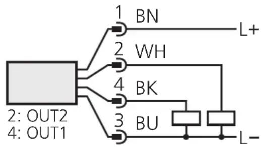
2 x p-switching
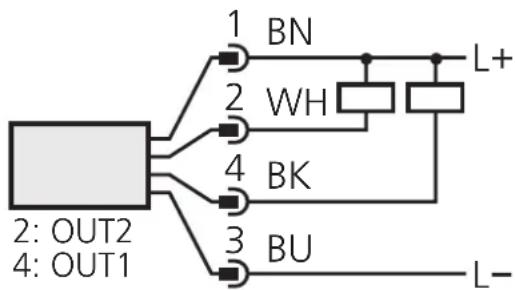
2 x n-switching
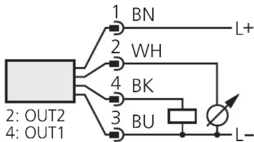
1 x p-switching / 1 x analogue
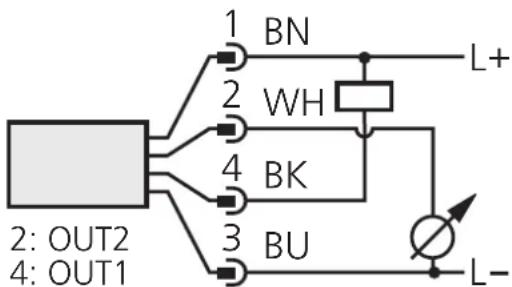
1 x n-switching / 1 x analogue
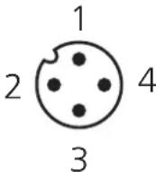
Connector view (sensor)
Core colours of ifm sockets:
1 = BN(brown) ,
2 = WH (white),
3 = BU (blue),
4 = BK (black).
Programming
| 1 | Mode/Enter Set | →SP1 | Press the Mode/Enter button several times until the respective parameter is displayed. |
| 2 | Mode/Enter Set | →100↓150 | Press the Set button and keep it pressed. The current parameter value flashes for 5s, then the value is increased* (incremental by pressing briefly or scrolling by holding pressed). |
| 3 | Mode/Enter Set | →SP1 | Press the Mode/Enter button briefly (= acknowledgement). The parameter is displayed again, the set parameter value becomes effective. |
| 4 | Change more parameters: Start again with step 1. | Finish programming: Wait for 15s or press the Mode/Enter button until the current measured value is indicated again. | |
*Decrease the value: Let the display of the parameter value move to the maximum setting value. Then the cycle starts again at the minimum setting value.
Select the display unit (Uni) before setting the switch points (SPx, rPx) or the limits for the analogue output signal (ASP, AEP). This avoids rounding errors generated internally during the conversion of the units and enables exact setting of the values.
If no button is pressed for 15s during the setting procedure, the unit returns to the Run mode with unchanged values.
The unit can be electronically locked to prevent unwanted adjustment of the set parameters: Press both pushbuttons for 10s (the unit must be in Run mode). Indication goes out briefly (acknowledgement of locking / unlocking).
Units are delivered from the factory in the unlocked state.
With the unit in the locked state is indicated briefly when you try to change parameter values.
Installation and set-up / operation
After mounting, wiring and setting check whether the unit operates correctly
Faults displayed during operation
| OL | Overload (above measuring range of the sensor). |
| UL | Underload (below measuring range of the sensor). |
| SC1 | Flashing: short circuit in the switching output 1*. |
| SC2 | Flashing: short circuit in the switching output 2*. |
| SC | Flashing: short circuit in both switching outputs*. |
*The output concerned is switched off as long as the short circuit exists.
Cleaning of the filter cover
If viscous and residues producing media clog the filter cover of the sensor (and thus reduce the measuring accuracy slightly), you can clean it.
- Unscrew the filter cover (B) (use a pair of pliers with plastic-covered jaws for this). Clean the cover thoroughly.
The vent (A) should only be cleaned by skilled personnel and with utmost care.
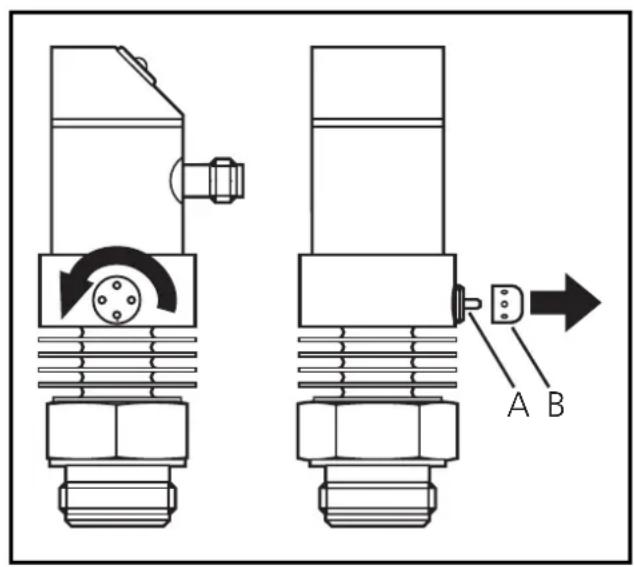

Possible medium residues must not be compressed and pressed into the vent. This could clog the filter system and reduce the measuring accuracy of the sensor.
- Screw the filter cover again tightly.
The sensor is sufficiently protected against harsh ambient conditions (protection IP 67). The protection rating can be increased by a special accessory (order no. E30043).
Technical information / Functioning / Parameters
Adjustable parameters
| SP1 SP2 | Switch-on point 1 / 2 Upper limit value at which the output changes its switching status. SP2 is active only if OU2 = Hno, Hnc, Fno or Fnc. |
| - P1 - P2 | Switch-off point 1 / 2 Lower limit value at which the output changes its switching status. rPx is always lower than SPx. The unit only accepts values which are lower than SPx. Changing the switch-on point also changes the switch-off point (the distance between SPx and rPx remains constant). If the distance is higher than the new switch point, it is automatically reduced (rPx is set to the minimum setting value). rP2 is active only if OU2 = Hno, Hnc, Fno or Fnc. Setting range for SPx / rPx: → page 49. |
| OU1 | Configuration of output 1 4 switching functions can be set: - Hno = hysteresis / normally open - Hnc = hysteresis / normally closed - Fno = window function / normally open - Fnc = window function / normally closed |
| OU2 | Configuration of output 2 4 switching functions and 2 analogue signals can be set: - Hno = hysteresis / normally open - Hnc = hysteresis / normally closed - Fno = window function / normally open - Fnc = window function / normally closed - I = analogue output 4 ... 20 mA - U = analogue output 0 ... 10 V |
| ASP | Analogue start point Measured value at which 4mA / 0V is provided. ASP is active only if OU2 = I or U. |
| AEP | Analogue end point Measured value at which 20mA / 10V is provided. Minimum distance between ASP and AEP = 25% scaling factor 4). AEP is active only if OU2 = I or U. Setting range for ASP / AEP: → page 49. |
| EF | Enhanced functions This menu item contains a submenu with additional parameters. You can access these parameters by pressing the SET button briefly. |
| HI LO | Min-Max memory for system pressure • HI: displays the highest measured pressure • LO: displays the lowest measured pressure Erase the memory: - Press the "Mode/Enter" button until HI or LO is displayed. - Press the "Set" button and keep it pressed until "-" is displayed. - Then press the "Mode/Enter" button briefly. |
| COF | Calibration offset The internal measured value (operating value of the sensor) is offset against the real measured value. • Setting range: -5 ... +5% of the value of the measuring range (with scaling as factory setting (ASP = 0% and AEP = 100%), • in steps of 0.1% of the value of the measuring range. |
| CAR | Calibration reset Reset the calibration set by COF to the value set at the factory. - Press the "Mode/Enter" button until CAR is displayed. - Press the "Set" button and keep it pressed until "-" is displayed. - Then press the "Mode/Enter" button briefly. |
| dS1 dS2 dr1 dr2 | Delay time for the switching outputs dSx = switch-on delay; drx = switch-off delay The output does not immediately change its switching status when the switching condition is met but when the delay time has elapsed. If the switching condition is no longer met when the delay time has elapsed, the switching state of the output does not change. • Setting range: 0 / 0.1 ... 50s adjustable in steps 01s (0 = delay time not active), • indicated in seconds. dS2 and dr2 are not active, if OU2 = I or U. |
| P-n | Output polarity 2 options can be selected: - PnP = positive switching - nPn = negative switching This setting applies to both switching outputs. |
| dAP | Damping for the switching outputs Pressure peaks of short duration or high frequency can be filtered out. dAP-value = response time between pressure change and change of the switching status in seconds (s). • Setting range: 0 ... 4s (0 = dAP is not active), • in steps of 0.01s. Correlation between switching frequency and dAP: fmax = 1/2 × dAP |
| dAA | Damping for the analogue signal Pressure peaks of short duration or high frequency can be filtered out. dAA-value = response time between pressure change and change of the switching status in seconds (s). • Setting range: 0 (= dAA is not active) / 0.1s / 0.5s / 2s. dAA is active only if OU2 = I or U. |
| d1,5 | Setting of the display 9 options can be selected: d1 = update of the measured value every 50ms d2 = update of the measured value every 200ms d3 = update of the measured value every 600ms The update interval only refers to the display. It has no effect on the outputs. ph = display of the measured peak value remains for a short time (peak hold). rd1, rd2, rd3, rph = display as d1, d2, d3, Ph; but rotated 180°. OFF = In the Run mode the display of the measured value is deactivated. If one of the buttons is pressed, the current measured value is displayed for 15s. Another press of the Mode/Enter button opens the Display mode. The LEDs remain active even if the display is deactivated. |
| Uni | Display unit The measured value and the values for SPx / rPx can be displayed in the following units: bAr (= mbar), H2O (inH2O), PA (= kPa). Select the display unit before setting the switch points (SPx, rPx) and the limits for the analogue output signal (ASP, AEP). This avoids rounding errors generated internally during the conversion of the units and enables exact setting of the values. Setting at the factory: Uni = bAr. |
Hysteresis function:
The hysteresis keeps the switching state of the output stable if the system pressure varies about the preset value. With the system pressure rising, the output switches when the switch-on point has been reached (SPx). With the system pressure falling the output does not switch back until the switch-off point (rPx) has been reached.
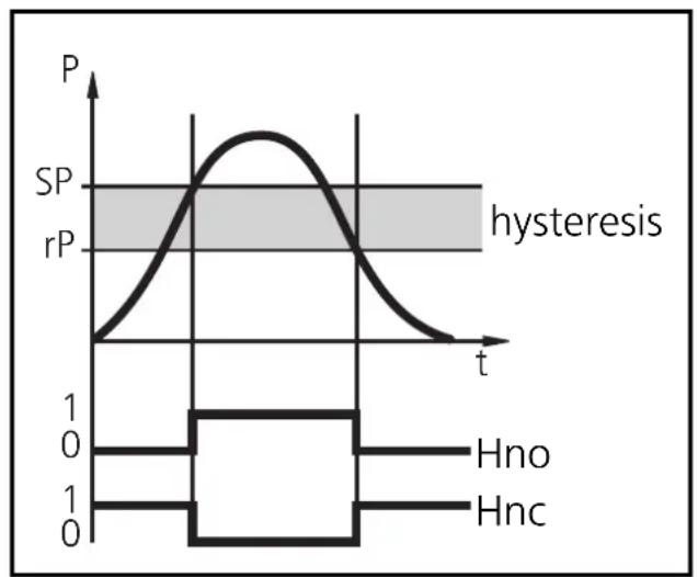
The hysteresis can be adjusted: First the switch-on point is set, then the switch-off point with the requested distance.
Window function
The window function enables the monitoring of a defined acceptable range. When the system pressure varies between the switch-on point (SPx) and the switch-off point (rPx), the output is switched (window function / NO) or not switched (window function / NC).
The width of the window can be set by means of the difference
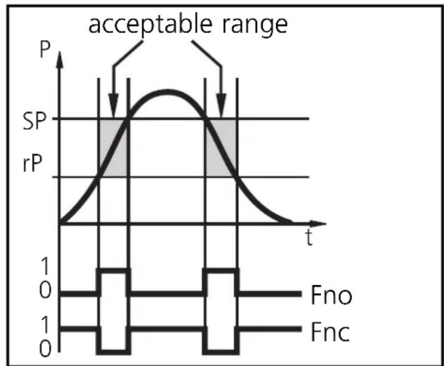
between SPx and rPx. SPx = upper value, rPx = lower value.
Scaling the measuring range (analogue output)
- With the parameter "Analogue start point" (ASP) the measured value at which the output signal is 4mA or 0V is defined.
- With the parameter "Analogue end point" (AEP) the measured value at which the output signal is 20mA or 10V is defined.
- Minimum distance between ASP and AEP = 25 % of the final value of the measuring range (scaling factor 4).
Voltage output 0 ... 10V
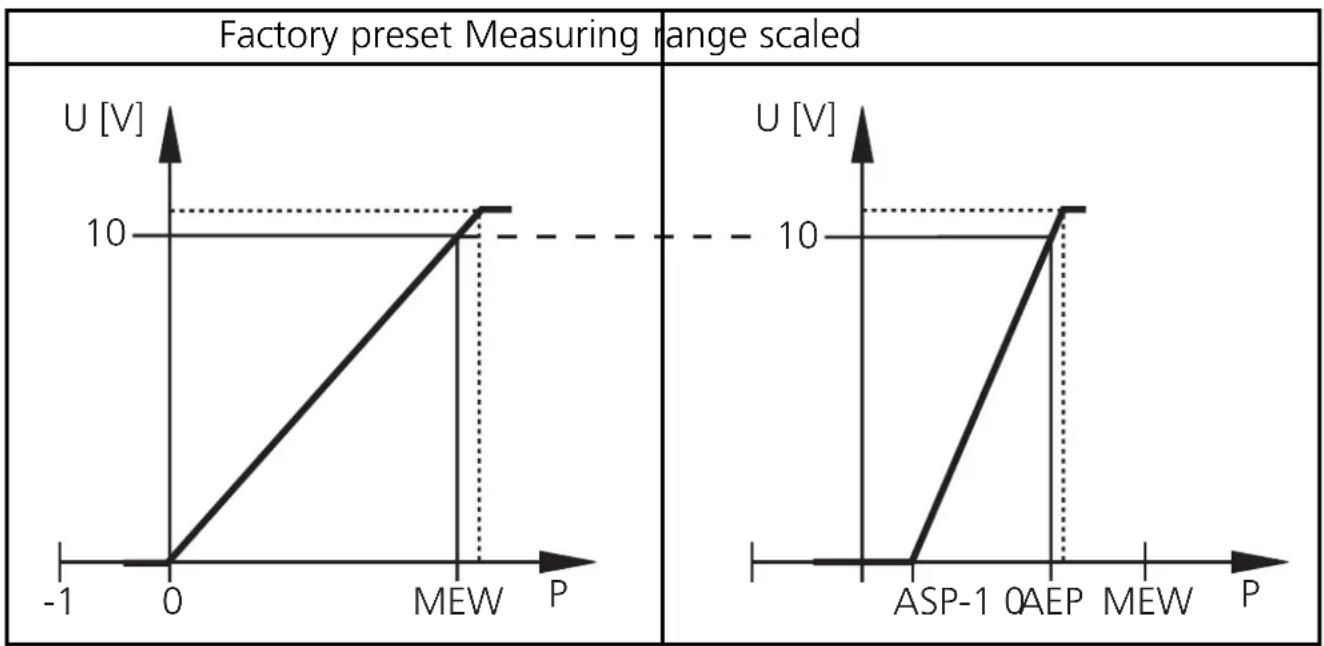
MEW = final value of the measuring range
The output signal is between 0 and 10V in the set measuring range.
It is also indicated:
System pressure above the measuring range: output signal >10V
Current output 4 ... 20mA
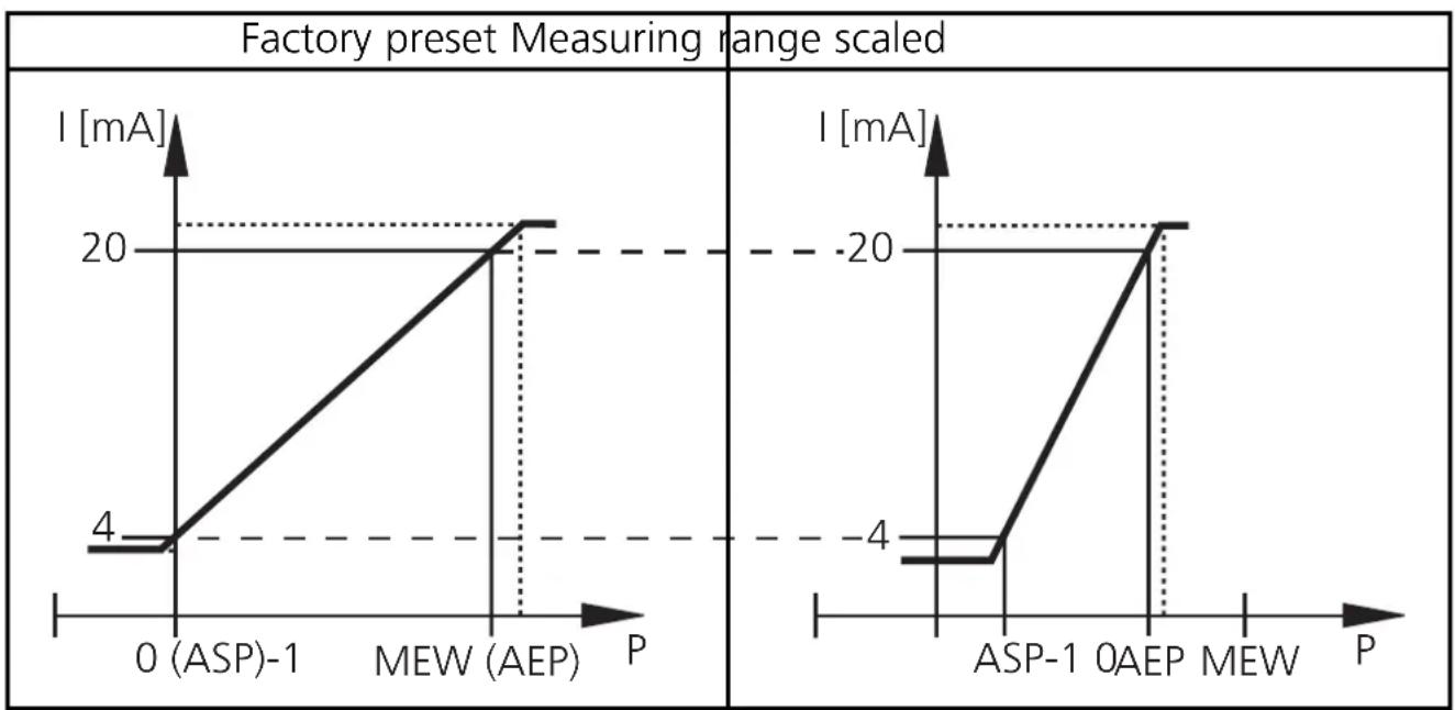
MEW = final value of the measuring range
The output signal is between 4 and 20mA in the set measuring range.
It is also indicated:
- System pressure above the measuring range: output signal >20mA .
- System pressure below the measuring range: output signal drops to max.
3.2mA (depending on the scaling).
Technical data
| Operating voltage [V] | 20 ... 30 DC |
| Current consumption [mA] | < 60 |
| Current rating [mA] | 2 x 250 |
| Short-circuit protection, reverse polarity protection / overload protection | |
| Integrated Watchdog | |
| Voltage drop [V] | < 2 |
| Power-on delay time [s] | 0.2 |
| Min. response time switching outputs [ms] | 3 |
| Switching frequency [Hz] | 170 ... 0.125 |
| Analogue output (measuring range scaleable) | 4 ... 20 mA / 0 ... 10 V |
| Max. load current output [Ω] | (UB - 10) x 50; 700 at UB = 24V |
| Min. load with voltage output [Ω] | 2000 |
| Min. response time analogue output [ms] | 3 |
| Accuracy / deviations (in% of the span)1) | |
| - Characteristics deviation (linearity, incl. hysteresis and repeatability)2) | < ± 0.6 |
| - Linearity | < ± 0.5 |
| - Hysteresis | < ± 0.1 |
| - Repeatability (with temperature fluctuations < 10K) | < ± 0.1 |
| - Long-time stability (in% of the span per year) | < ± 0.1 |
| - Temperature coefficients (TEMPCO) in the compensated temperature range 0 ... +80°C (in% of the span per 10 K) | |
| - Greatest TEMPCO of the zero point | < ± 0.1 |
| - Greatest TEMPCO of the span | < ± 0.4 |
| Materials (wetted parts) | stainless steel (316S12); ceramics (99.9 % Al2O3); PTFE |
| Housing material | stainless steel (316S12); Pocan; PC (Macrolon); PEI; EPDM/X (Santoprene); FPM (Viton) |
| Protection | IP 67 / III |
| Insulation resistance [MΩ] | > 100 (500 V DC) |
| Shock resistance [g] | 50 (DIN / IEC 68-2-27, 11ms) |
| Vibration resistance [g] | 20 (DIN / IEC 68-2-6, 10 - 2000 Hz) |
| Switching cycles min. | 100 million |
| Operating temperature [°C] | -25 ... +80 |
| Medium temperature [°C] | -25 ... +125 (+145 max. 1h) |
| Storage temperature [°C] | -40 ... +100 |
| EMC | IEC 1000/4/2 ESD: 4 / 8 KV |
| IEC 1000/4/3 HF radiated: 10 V/m | |
| IEC 1000/4/4 Burst: 2 KV | |
| IEC 1000/4/6 HF conducted: 10 V | |
1) all indications are referred to a turn down of 1:1
2) limit value setting to DIN 16086