
HS2LCDWFP9 - Security and Access Control System DSC - Free user manual and instructions
Find the device manual for free HS2LCDWFP9 DSC in PDF.
| Product Type | Security and Access Control System Keypad |
| Brand | DSC |
| Model | HS2LCDWFP9 |
| Power Supply | 13.8 VDC nominal (via compatible control panel) |
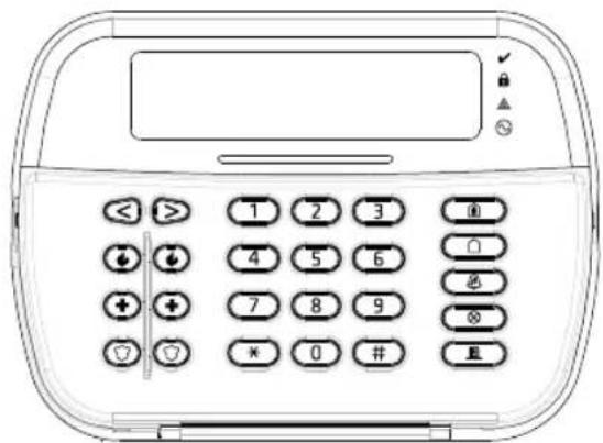
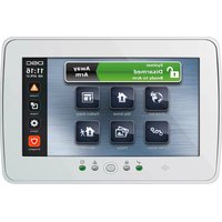
| Display | Backlit LCD, 2 lines of 16 characters |
| Function Keys | 5 programmable keys |
| Status LEDs | Ready (green), Armed (red), Trouble (yellow), AC (green) |
| Zone Input / PGM Output | 1 zone input or 1 PGM output selectable |
| Proximity Tag | Yes (P model) |
| Light Bar | Yes (P model), 3 flashes for valid tag |
| Low Temperature Sensor | Yes, built-in |
| Tamper Contact | Yes, wall mounting |
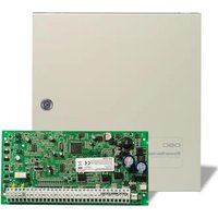
| Compatibility | PowerSeries Nco control panels (HS2016/32/64, HS2014, HS2128) |
| Communication | Corbus 4-wire bus |
| RF Frequency (RF models) | 433 MHz (HS2ICNRF4/HS2LCDRF4) |
| Temperature Range | -10°C to +55°C (14°F to 131°F) |
| Max Humidity | 93% RH non-condensing |
| Protection Rating | IP30, IK04 |
| Maintenance | No user-serviceable parts. Clean with a soft, dry cloth. |
| Security | Tamper protection, RF jamming detection, wireless supervision |
| Repairability | No user-serviceable parts. Contact a certified installer. |
Frequently Asked Questions - HS2LCDWFP9 DSC
User questions about HS2LCDWFP9 DSC
0 question about this device. Answer the ones you know or ask your own.
Ask a new question about this device
Download the instructions for your Security and Access Control System in PDF format for free! Find your manual HS2LCDWFP9 - DSC and take your electronic device back in hand. On this page are published all the documents necessary for the use of your device. HS2LCDWFP9 by DSC.
USER MANUAL HS2LCDWFP9 DSC
HS2LED/HS2ICON(P)(RF)X/HS2LCD(RF)(P)X V1.3
Installation Instructions/Instructions d'installation/Instrucciones de instalacion/Instruções de instalacao English, François, Espanol, Portugues
PowerSeries neo
DSC Fram Tyco Security Products


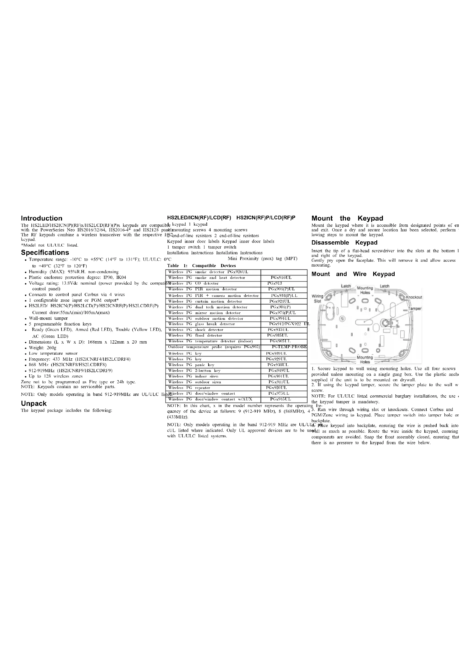
Introduction
The HS2LED/HS21CN(P)(RF)x/HS2LCD(RF)(P) x keys are compatible Keypad 1 keypad with the PowerSeries NoC 1920136/32/4H 192016-4" and HS2128 partmounting screws
The RF key pads combine a wireless transceiver with the respective HS2_end - of - line resistors 2 end-of-line res
Model not UL/ULC listed. 1 tamper switch 1 tamper switch
Specifications
- Temperature range: -10°C to -55°C (14°F to 131°F); UL/ULC: 0°C Mini Proximity (prox) tag (MPT)
to +49^ (32°F to 120°F)
Humidity (MAX): 93% R.H. non-condensing
Plastic enclosure protection degree: IP30, IK04
Voltage rating: 13.8Vdc nominal (power provided by the compact control panel)
- Connects to control panel Corbus via 4 wires
- I configurable zone input or PGM output
HS2LED/HS21CN(P)/HS2LCD(P)/HS21CNRF(P)/HS2LCDRF(P)
Current draw:55mA(min)/105mA(max)
Wall-mount tamper
-
5 programmable function keys
-
Ready (Green LED), Armed (Red LED), Trouble (Yellow LED), AC (Green LED)
Dimensions (L x W x D): 168mm x 122mm x 20 mm
Weight: 260g
Low temperature sensor
Frequency: 433 MHz (HS2ICNRF4/HS2LCDRF4)
868 MHz (HS2ICNRF8/HS2LCDRF8)
912-919MHz (HS2ICNRF9/HS2LCDRF9)
- Up to 128 wireless zones
Zone not to be programmed as Fire type or 24h type.
NOTE: Kcypads contain no servicable parts
NOTE: Only models operating in band 912-919MHz are UL/ULC li
Unpack
The keypad package includes the following:
Table 1: Compatible Devices
| Wireless PG smoke detector PGx926UL. | |
| Wireless PG smoke and heat detector PGx916UL. | |
| Wireless PG CO detector PGx913. | |
| Wireless PG PIR motion detector PGx904(P)UL. | |
| Wireless PG PIR + camera motion detector PGx934(P)UL. | |
| Wireless PG curtain motion detector PGx924UL. | |
| Wireless PG dual tech motion detector PGx984(P) | |
| Wireless PG mirror motion detector PGx974(P)UL. | |
| Wireless PG outdoor motion detector PGx994UL. | |
| Wireless PG glass hreak detector PGx912/PGX922 U | |
| Wireless PG shock detector PGx935UL. | |
| Wireless PG flood detector PGx985UL. | |
| Wireless PG temperature detector (indoor) PGx905UL. | |
| Outdoor temperature probe (requires PGx905) PGTEMP-PROBE. | |
| Wireless PG key PGx939UL. | |
| Wireless PG key PGx929UL. | |
| Wireless PG panic key PGx938UL. | |
| Wireless PG 2-button key PGx919UL. | |
| Wireless PG indoor siren PGx901UL. | |
| Wireless PG outdoor siren PGx911UL. | |
| Wireless PG repeater PGx920UL. | |
| Wireless PG doorWindow contact PGx975UL. | |
| Wireless PG doorWindow contact w/AUX PGx945UL. |
NOTE: In this chart, x in the model number represents the ope quency of the device as follows; 9 (912-919 MHz), 8 (868MHz (433MHz).
NOTE: Only models operating in the band 912-919 MHz are UL cUL listed where indicated. Only UL approved devices are to be with UI/ULC listed systems.
HS2LED/ICN(RF)/LCD(RF) HS2ICN(RF)P/LCD(RF)P
Mount the Keypad
Mount the keypad where it is accessible from designated points of er and exit. Once a dry and secure location has been selected, perform lowing steps to mount the keypad.
Disassemble Keypad
Insert the tip of a flat-head screwdriver into the slots at the bottom I and right of the keypad.
Gently pry open the faciplate. This will remove it and allow access mounting.
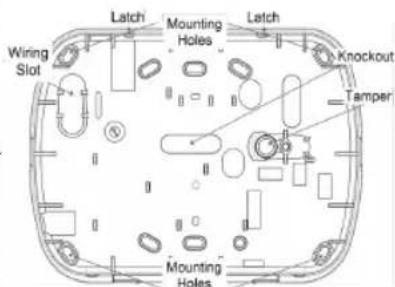
Mount and Wire Keypad
-
Secure kcpad to wall using mounting holes. Use all four screws provided unless mounting on a single gang box. Use the plastic arch supplied if the unit is to be mounted on drywall.
-
If using the keypad tamper, secure the tamper plate to the wall w screw.
NOTE: For UL/ULC listed commercial burglary installations, the use the keypad tamper is mandatory.
-
Run wire through wiring slot or knockouts. Connect Corbus and PGM/Zone wiring to keypad. Place tamper switch into tamper hole or backplate.
-
Place keypad into backplate, ensuring the wire is pushed back into wall as much as possible. Route the wire inside the keypad, ensuring components are avoided. Snap the front assembly closed, ensuring that there is no pressure to the keypad from the wire below.
NOTE: If any tension is found between the front keypad assembly wiring, open the keypad, reroute the wire and close again. Rcpcat steps until the keypad is closed properly.
Wiring
1.Before wiring the unit, ensure that all HS2LED/HS2ICN(RF) power (AC transformer and battery) is dis connected from the control panel. 2. Connect the four Corbus wires from the RED R BLK B to the keypad terminals. Refer to the diagram: YEL Y GRN G
If programmed as an input, a device - subzone P/Z 1
as a door contact ^ 串 may be connected to upqm P / Z^ terminal of the keypad. This elim
mates the need to run wires back to the control panel for the device. To connect the zone, run one wire from device to the / ^ terminal and the other wire from the device to (black) terminal. For powered devices, run the red wire to the R (j) terminal and the black wire to the B (negative) terminal. When using of line supervision, connect the zone according to one of the config described in the PowerSeries Neo Reference manual.
NOTE: For UL/ULC installations, the zone input is a supervised by (SFOI/DFOL). The supervision resistor is 560Ω. If no FOI, super is used, there is a three foot maximum distance required for the co-occlusion of the two sensors.
device. Use only in conjunction with UI/UC listed devices. NOTE: This initiating device connected to this input contact is not used for medical or fire applications.
- If the 'P/Z' terminal is programmed as an output, a small relay DSC model RM-1 or RM-2) or buzzcr or other DC operated device connected between the positive supply voltage and the 'P/Z' termina (max load is 50mA
NOTE: For UL/ULC-listed installations, use UL/ULC listed devices.
Apply Power
Once all wiring is complete, and the equipment is secured to the hong structure with at least two screws, apply power to the control panel.
- Connect the battery leads to the battery.
- Connect the AC transformer.
For more information on control panel power specifications, see the Series Neo Reference manual.
program the Keypad
-
Press [^*][8][ [installer Code]. 4
2.Use the [ < ] ] keys to navigate through the menus or jump directly to specific section by entering the section number. Toggle Xo () and off options in each section or by. utating data fields. Toggle options are enabled or disabled by pressing the cor-.
responding number on the keypad. For example, to enable toggle options 1 and 4,press the [1] and [4] keys.All enabled options are displayed (see the following diagram). -
To input data, use the [<] [>] keys to select a character then press keypad button for the number/letter.
The thing the [< ][>] keys, scroll to the next character and repeat the POSITIVE. For information on entering HEX data, refer to the Powers end.
Language Programming
Enter [000][000]. Enter the two-digit number corresponding to the vision desired:
Injected Table 2: Languages
| 01= English (default) | 10 = German 20 = Romanian | |
| 11 = Swedish 21 = Russian | ||
| 02 = Spanish 12 = Norwegian 22 = Bulgarian | ||
| 03 = Portuguese 13 = Danish 23 = Latvian | ||
| 04 = French | 14 = Hebrew 24 = Lithuanian | |
| 05 = Italian | 15 = Greek | 25 = Ukrainian |
| 06 = Dutch | 16 = Turkish | 26 = Slovak |
| 07 = Polish | 17 = Future Use 27 = Serbian | |
| 08 = Czech | 18 = Croatian | 28 = Estonian |
| 09 = Finnish 19 = Ungarian 29 = Slovenian | ||
Enroll the Keypad
- Keypad can be enrolled automatically or manually. In either case, serial number of the device is used as an identifier.
- Power: Note: If there is no keypad enrolled on the system, once you port the keypad will display the message: Press any key to enroll. Other keypads can then be enrolled from the first keypad. Use one of the lowing enrollment options:
[902][000] Auto Enroll
When this mode is selected, the total number of keystads currently en is displayed on the keypad. 1. Enter [902][000] to begin the auto-enrollment of new keystads. As device is enrolled, the keypad displays the model type, serial number slot assignment. Keypads are assigned to the next available slot.
[902][001] Manual Enroll
To manually enroll individual keystads: 1. Enter [902][001] or use the [<][>] keys and press [^ ] 2. When prompted, enter the serial number of the keypad found on t of the device.
-
An error tone is sounded if an invalid serial number is received.
enrolled, the device model, serial number and slot assignment are displayed. Keypads are enrolled into the next available slot for the device. The slot assignment can be changed using the [<][>] keys. -
To cancel the enrollment of a module, press [F].
NOTI: Once the maximum number of devices have been enrolled, and the tones and a warning message is displayed.
[902][002] - Module Slot Assignment (LED, ICON)
This section is used to change the slot number in which a module is enrolled. To change the slot number:
- Enter [902][002] or use the [<][>] keys and press [^] .
-
Enter the serial number of the module.
-
When prompted, enter the new two-digit slot number. The previous assignment is replaced with the new one. An error tone sounds if an invalid slot number is entered.
[902][003] - Module Slot Assignment (LCD
Similarly to [002], this section is also used to change the slot numbe module. With this option, however, the serial number is not required. change the slot number:
-
Enter [902][003] or the use the [ ][ ] keys and press [^]
-
Use the [< ][>] keys to locate the module then press [^] to select. 3. Enter the new two-digit slot number. The previous slot assignment is replaced with the new one. An error tone sounds if an invalid slot n is entered.
[902][101] Unenroll Keypads
```python 100 [Enter [902][101] or use the [<][>] keys and press [*]. 2. Use the [<][>] keys to scroll to the specific keypad to delete.
- Press [] to select the module and when prompted, press [] again [1] - A, B, C 1 [5] - M, N, O, 5 [9] - Y, Z, 9, 0 [2] - D, E, F 2 [6] - P, Q, R, 6 [0] - Space
[903][101] Confirm Keypad
To confirm the enrollment of individual kcpads and to locate them PERANGE CASE will toggle the next letter entries between upper
-
Enter [903][101] or use the [< ][> and press [ ] . ASCII ENTRY - Used to enter uncommon characters. Valid entries 2. Use the [< ][>] keys to scroll to the applicable keypad. The moduI from 000 to 255.Use the [< ][> keys to scroll through the character serial number and slot number are displayed on the keypad and the a 3-digit number from 000-255. Press [ ] to enter the character LEDs on the device flash. the label.
-
To confirm the kcpad, prcess [^*] . If communication with a moduLcLiAR TO END - Clicars the display from the character where the lost at the time of confirmation, a warning message is displayed for was located to the end of the display. clear display - Clears the entire label.
Assign a Partition to the Keypad
The keypad must be assigned to a partition if supervision or keypad Label Library are required. Keypad assignments and keypad option programming must be Label Library is a database of words commonly used when pro done at each keypad individually. graming labels Individual words can be combined as needed (e.g.
At each keypad installed on the system:
-
Press [^*][8][Installer Code]
-
Enter [861]–[876] for Keypad Programming and Keypad Partition Character of the second line and then add the word
corresponding to keypads 1-16.
-
Press [^*] for partition assignment.
-
Enter 01 to 08 for partition assignment or use the [<]_> keys to 2scaller [001] (to program the label for zone 01), or use the [<][> to the specific partition if partitioning is not used, enter [01]. For Global to the Zone Labels and then press [a]. The current label name is labeled as:
kcpda, cncf [00]. 5. Press [n] twice to exit programming.
- Continue this procedure for each keypad until all have been assigned to the correct partition. 4. Press [+] again to select the "Word Entry" option. 5. Enter the 3-digit number corresponding to a word (see Words Lit
Program Labels (LCD keypads)
- Press [^*]|8| [Installer Coda].
- Press [^*] and use the [· < ] keys to scroll to Zone Labels and pressTo add another word, repeat the previous procedures from step 3.
where The first zoom is displayed. Alternatively enter [0000f001] -
To add a space, press the right scroll key [>
-
Use the < lf > 1 keys to scroll to the zone label to be programmed and
prss [ ] or enter the zone number (c.g., 001, for zone label 1).
- Use the [· < ][· >] keys to scroll to the desired character's location, using
the [< ][>] keys. Broadcast LCD Labels
- Enter the number of the corresponding character group until the desired more than one LCD keypad is present on the system, labels program character is displayed (see the following table). Example, press the "en one keypad will be broadcast to all other LCD keypads, after the key thus times to enter the letter "Hi". Press the "II" key from time to time and press the "Enter" key.
key three times to the letter F. Press the 2 key four times when
er the number 2 . Press [ ] , then scrol to Save . Press [ ] agto save the label . To delete a character use the [<] keys to movs the
cursor under the character, then press [0]. If any key other than [<][LCD] Keypads
pressed before [0], the cursor moves one space to the right and deletes that character. Press [*][6][Master Code].
-
Use the [<] keys to scroll to either Bright Control, Contrast Co or Buzzer Control.
-
Press [^*] to select one of the following settings:
Brightncss/LED Bar Control -15 backlighting levels available.
- Contrast Control -15 display contrast levels available
Buzzer Control - 15 buzzer control levels available.
- Use the [< ]|>] keys to scroll to the desired setting.
Ding Keypad Programming
In Nuss. [^*] [8] Installer, Codel
- Select one of the programming options identified in the following.
cursor
[860] Keypad Slot Number
Not for programming; the two-digit slot number is displayed for infor ational purposes only.
[861]-[876] Keypad Programming Sections
[809] Address of Partition
Default 01
A.2-digit entry is required to assign the keypad to a partition. Valid
entries are 00-32.
NOTE: LED and ICON keypads must not be assigned as global keyp
[001]-[005] Keypad Function Key Programming
keys w 10 program a function key
Press [7][8][Installer Code]
-
Enter [861]-[876] for keypad programming.
-
Enter [001]-[005] for function keys 1-5 or use the [≤ ][≥ ] keys and
[4]
YbF a 2-digit number to assign a function key operation - [001-0]
the following table:
-
Repeat from step 3 until all function keys are programmed
-
Press [#] twice to exit Installer Programming.
Table 3: Function Key Assignment
| Function Key | Button | Valid Range | Default | Function | ||
| [001] | Key 1 | 00-68 | 03 | Stay Arm | ||
| [002] | Key 2 | 00-68 | 04 | Away Arm | ||
| [003] | Key 3 | 00-68 | 06 | Chime ON/OFF | ||
| [004] | Key 4 | 00-68 | 22 | Command Output 2 | ||
| [005] | Key 5 | 00-68 | 16 | Quick Exit |
Keypad Function Keys
Refer to your system installation manual for a complete list of available default function key options.
[00] - Null [13] - Global Away Arm [31] - Local PGM ActiL
[02] - Instant Stay [14] - Global Disarming [32] - Bypass Mode Arm
[03] - Stay Arm [16] - [^*][0] Quick Exit [33] - Bypass Recall
[04] - Away Arm [17] - Arm Interior [34] - User Programming
[05] - [e][9] No-Enrty21] - [e][7][1]Command
Am Output 1 [35] - User Functions
[06] - [a][4] Chime [22] - [a][7][2]Commun37] Time & Date ProON/OFF Output 2 gram
[ |07| - [{}^{#}|6|---\dots|4] \quad [23] - [{}^{#}|7||3|Command] \quad 39] - \text{Trouble Display System Test Output } 3 ]
[09] - Night Arm [24] - [6][7][4]Command Output 4 [40] - Alarm Memory
[12] - Global Stay [29] - Bypass Group [61]-[68] - Partition Arm Recall Select 1-8
[011] Keypad Input/Output Programming Zone /PGM Number Default 000 |
[012] Local PGM Output Pulse Activation Minutes (00-99) Seconds (00-9
[021] First Keypad Options
Default Opt. ON OFF
ON | Fire Key Enabled Fire Key Disabled
ON 2 Medical Key Enabled Medical Key Disabled
ON 3 Panic Key Enabled Panic Key Disabled
ON 4 Display Access Codes Display Xs When Programming Access When Programming Codes
NOTE: For EN50131-1/EN50131-3 compliant systems, section [021], options 1 and 2 shall be OFF.
[022] Second Keypad Options
Opt. ON OFF 1 Local Clock Display Local Clock Display OFF ON ON Local Clock Displays Clock Displays AM/PM 2 Local Clock Displays 24/hr Auto Alarm Mem Auto Alarm Mem Scroll 3 Scroll ON OFF For Future Use For Future Use 5 Power LED Enabled Power LED Disabled 6 Power LED AC Prescrifower LED AC Present ON OFF ON 7 Alarms Displayed Alarms Not Displayed While Armed While Armed. 8 Auto-Scroll Open ZoneAuto-Scroll Open Zones ON OFF
[023] Third Keypad Options
1 Opt. ON OFF 1 Armed LED Power Armed LED Off in Sleep Save Mode 1 2 Keypad Status Shows Keypad Status Shows Stay Arm Stay/Away Arm 3 5th Terminal is PGM 5th Terminal is Zone Input Output 4 Prox Tag Will Arm/Disarm Tag Does Not arm Disarm Local Display of TemNo Local Display of Tem perature perature Low Temperature Warhow Temperature Warning ing Enabled Disabled
[030] Downloaded LCD Message
NOTE: Clock display (Section [022], Option 1) must be enabled.
[031] Downloaded LCD Message Duration
Default: 000 | | | (Valid entries are 000-255, 000-0 Unlimited Display)
This number represents the number of times the downloaded message must be cleared before it is permanently removed. This message can be cleared by pressing any key.
[041] Indoor Temperature Zone Assignment Default: 000 | (Valid entries are 000-128)
[042] Outdoor Temperature Zone Assignmer
Default: 000 (Valid entries are 000-128)
[101]-[228] Door Chime for Zones
Default:01
The keypad can be programmed to make up to four different chime for individual zones. (c.g., for Zone 1, enter section [101], for Zone 2 enter section [102]
01 6 beeps 04 Alarm Tone (4s duration)
02 Bingbing tone 05 Zone Name 03 Ding dong tone
[991] Reset Keypad Programming to Facto Defaults
- Press [B][R] [Installer Code]. 2. Enter [991].
3.Use the [ < ][ ] keys to scroll to the applicable keypad.
4.4. Press [^*] to select the keypad.
-
Re-enter [Installer Code].
-
Press [^*] to reset the selected keypad to factory defaults
Proximity (Prox) Tags Support (HS2ICNP/HS2ICNRFP/HS2LCDP)
The proximity tag can perform any keypad function that would norme require a user access code or to activate a programmable output. Pres the tag to the tag reader ( ) or to the left of the keypad LCD.
Assign Proximity Tags
Using an LCD keypad:
1. Press [*/][5][Master/Supervisor Code].
2. Enter a 4-digit user code.
3. Press 2.
4. Pass the enrolled tag near the tag reader on the keypad.
Delete Proximity Tags
To delete a prox tag, select the user as outlined previously.Swipe ciated prox tag. The alarm system recognizes the tag. Press [+] to when prompted.
LED Bar
On the HS21CNP/HS21CNRFP/HS2LCDP keycaps, a blue LED bar ates that a prox tag is approaching.
-
The LED bar flashes three times when a valid proxy tag is being the keypad.
-
If the prox tag is invalid, the LFD bar stays on steadily and the sounds an error lone.
-
The brightness of the LED bar is adjustable from the [^*||6] to the backlight brightness is modified, the LED bar brightness is changed accordingly.
Downloading
The HS2LCDFR/HS2ICNRF products can be programmed over DLS. This auto-detects the keyboard type and downloads programming accordingly.
Wireless Device Setup and Programming
(HS21CNRF(P)x/HS2LCDRF(P)x)
This section describes how to enroll and program wireless devices as contacts, motion sensors and sirens on the alarm panel.
[804][000] Enroll Wireless Devices
-
Once the HSM2HOST is installed and enrolled on the alarm panel, wireless devices can be enrolled using the following method: Enter Installer Programming section [804][000]:
-
When prompted, either activate the device (see device installation sheet) to enroll immediately or enter a device ID number. Do the pre-enroll devices then enroll them later at the customer site.
The alarm panel determines the type of device being enrolled and the appropriate programming options.
Table 4: Wireless Device Options
| Device Type Programming Options | |
| ctcZone | (01) Zone type(02) Partition assignment. (03) Zone label |
| Wireless key | (01) Partition assignment. (02) User label |
| dic- | |
| Siren read by | (01) Partition assignment. (02) Siren label |
- Use the scroll keys or type in the corresponding number to select options.
- Scroll through the available selections, key in a number or context appropriate.
- Press [^*] to accept and move to the next option.
- Once all options are configured, the system prompts to enroll the device.
- Repeat the process described above until all wireless devices are enrolled.
NOTE: The configuration options listed above can be modified using [911] Modify Device.
[804][001]-[716] Wireless De
To configure wireless devices:
- Enter Installer Programming section [804] then select one of the following sub-sections:
Table 5: Wireless Zone Sub-Sections
| Sub-Section | Description |
| 001-128 | Configure wireless zones |
| 551-556 | Configure wireless sirens |
| 601-632 | Configure wireless keys |
| 701-716 | Configure wireless keypads |
reselect a device to configure using the scroll keys or go directly to cific device by entering a hotkey.
3. Use the scroll buttons or enter a hot key to select a configuration for the device. See device sheets for details.
4. Press [^*] to accept and move to the next option.
5. Once all options are configured, the system returns to the base figuration menu.
Repeat the process described above to configure other wireless devices.
[804][801] RF Jam Detect
RF jam detection (continuous interfering transmissions on the radio net work) can be turned on or off. When on, RF jamming is logged and fed.
To configure RF jamming:
1. Enter Installer Programming section [804][801].
2. Select one of the following options by scrolling or entering the h:
Table 6: Jam Detect Options
| 00 an | Enabled/Disabled | Jamming detection and reporting is enabled/disabled Note: Must be Enabled UL/UL LC listr installations. |
| 01 | UL 20/20-USA Continuous RF jamming for 20 seconds | |
| 02 | EN 30/60-Europe | 30 seconds of accumulated jamming within 60 seconds |
| 03 next | Class 6 30/60-British | As EN (30/60) but reported only if the ming duration exceeds 5 minutes |
-
Press [^*] to accept the selection.
-
Press [#] to exit the section.
[804][802] Wireless Supervision Window
This option is used to program the length of time a wireless device absent from the system before a fault is generated.
NOTE: For EN installations, 1 hour or 2 hours must be selected.
When option 06 is used, which configures the system to generate fault indications after a device has been detected as absent for 24 hours, smoke detectors generate a fault condition after a maximum of 18 hours when 200s supervision toggle option is disabled.
To program the Wireless Supervisory Window:
-
Enter Installer Programming section [804][802].
-
Select one of the following options by scrolling or entering the hc
Table 7: Wireless Supervisory Window Options
| 00 Enabled/Disabled |
| 01 After 1 Hour |
| 02 After 2 Hour |
| 03 After 4 Hour |
| 04 After 8 Hour |
| 05 After 12 Hour |
| 06 After 24 Hour |
-
Press [^*] to accept the selection.
-
Press [#] to exit the section.
NOTE: For UL Residential Burglary (UL1023), Home Health Care (UL1637), ULC Residential Burglary (ULCORD-C1023) installations
For UL Residential Fire (UL985) installations, the maximum supervisory window is set to 200s.
For UL Commercial Burglary (UL1610/UL365) and ULC Residential (ULC-SS45), the maximum supervision window shall be set to 4 hr
[804][810] Wireless Option 1
To program wireless options:
-
Enter Installer Programming section [804][810].
-
Select one of the following options by scrolling or entering the
Table 8: Wireless Options
| 01 | RF Deli- quency | On: the system cannot be arnaed if a wireless sup- visory trouble exists. An RF delinquency trouble is erated. Off: wireless supervisory troubles do not prevent an |
| 02 | Wireless Supervisory/ RF Jam Alarm | On: if a supervisory or jamming trouble occurs during Away arning, the siren activates and the event is logged and reported. Off: supervisory or RF jam troubles during Away ing do not activate the siren or get logged and report |
| 03 | Module Tamper | On: module tampers are logged and reported. Off: module tampers are not logged or reported. |
| 04 | Fire Sup- vision | On: fire devices are supervised every 200 seconds, a the device fails to report within this window, a su- vision trouble is generated. Off: fire devices follow the supervisory window pro- grammed in section 802, up to a maximum of 18 The supervisory window can be programmed with a higher value, but detectors still go into fault after hours. |
- Press [] to accept the selection and [#] to exit.
[804][841] Visual Verification Programming
To program wireless options:
1. Enter Installer Programming section [804][841].
2. Select one of the following options by scrolling or entering the
Table 9: Visual Verification Sub-Sections
| 001 on | Visual Veri- fication | On: Alarms trigger image capture from PIR eras Off: Alarms do not trigger image capture from PIR Cameras |
| Fire 002 r- | View Time Win- dow | 01 Alarm + 5 Minutes 02 Alarm + 15 minutes 03 Alarm + 1 Hour |
| 003 onkey | View Other Alarms | 01 Fire key enabled/disabled 02 Duress key enabled/disabled 03 Medical key enabled/disabled 04 Panic key enabled/disabled |
[804][901]-[905] Delete Wireless Devices
To delete wireless devices:
- "Enter Installer Programming section [804] then select one of the following sub-sections:
Table 10: Module Label Sub-Sections
| Sub-Section | Description |
| 901 Delete | wireless zone devices |
| wireless key | |
| #902 Delete | sircons |
| 903 Delete | repeaters |
| 904 Delete | |
| 905 Delete | keypads |
密 : Select a device to delete using the scroll keys or go directly to the specific device by entering a hotkey. 3. Press [^*] to delete or [n] to exit.
[604][921]-[925] Replace Wireless Devices
Use this option to replace a faulty device enrolled on the system with another device of the same type while maintaining the configuration original. The faulty device does not need to be deleted. To replace less device:
- Enter Installer Programming section [804] then select one of the following sub-sections.
Table 11: Replace Device Sub-Sections
| Sub-Section | Description |
| 921 | Replace wireless zone devices |
| 922 | Replace wireless keys |
| 923 | Replace sirens |
| 924 | Replace repeater |
| 925 | Replace kcvpad |
-
Press [^*] to select a sub-section. The first available device is disassembled.
-
Select a device to replace using the scroll keys or go to a specific device by entering a hotkey. Press [4]. When prompted, activate the (full enrollment) or enter the device ID (pre-enrollment). A message is played confirming enrollment.
[804][990][001- 005] Show All Devices
Use this section to review wireless devices enrolled on the system and view serial numbers associated with each device.
To review wireless device information:
- Enter Installer Programming section [804][990] then select one of the following sub-sections:
Table 12: Wireless Device Sub-Sections
| Sub-Section Descriptions | |
| 001 | All zones |
| 002 | Repeaters |
| 003 | Sirens |
| 004 | Wireless keys |
| 005 | Keypads |
- Press [+] to select a wireless device type. The first available device displayed.
- Use the scroll keys to view the enrolled devices.
NOTE: This option is not fully supported by LED and ICON kypad
[904] Placement Testing Wireless Devices keypads only)
This test is used to determine RF signal status for wireless devices a can be performed at a system keypad or at the individual device. The instructions pertain to testing at the keypad. For instructions on places at the device, refer to the installation sheet provided with the equipment. The following test modes are available:001-128 - Test wireless zones.
fol-
Table 13: Wireless Device Placement Test Modes
| 001-128 | Test wireless zones | Test wireless devices individually by zone. |
| 520 Test all repeaters | Test each enrolled wireless repeater. 521-528 for repeaters 1-8. | |
| 550 Test all sireas | Test each enrolled wireless siren. 551-556 for sires 1-16 | |
| 600 Test all wireless keys | Test individual wireless keys.Once in section,press a button on the wireless to begin the test. 601-632 for wireless keys 1-32. | |
| 700 Test all keypads | Test each enrolled keypad 701-716 for keypads 1-16. |
Two test results are provided:
24-hour: Average results of signal strength testing over a 24-hour period.
Now: Signal status results of the current test.
During testing, the Ready and Armed LED's flash to indicate data received. A flashing Trouble LED indicates RF interference. The following status indicators may be displayed:
Table 14: Wireless Device Status Indicators
| LCD Status Repeater [905] | ||
| Strong Strong signal strength Repeater 1 | ||
| Good Good signal strength Repeater 2 | ||
| Poor Poor signal strength Repeater 3 | ||
| 1-Way The device is operating in 1-way mode only. The alarm panel cannot configure or control the device | ||
| Not Displayed as the Now result if no test is performed. | ||
| None Always displayed as the 24-hour result with no testing wireless keys. | ||
NOTE: For UL/ULC installations, only STRONG signal levels are acceptable.
- Ensure that the wireless zone is not assigned to a zone used by HSM2108 modules, an on-board zone or a kypad zone.
- Ensure that the zone is programmed for something other than "Null Operation".
3. "Poor" or no results are received from a module placement test. Verify that you are testing the correct zone.
- Verify the device is in range of the keypad. Test the device in the same room as the receiver.
Confirm that the keypad is properly connected to the Corbus. Check that the zone is being tested correctly. Refer to the instructions that came with the device.
- Check that the batteries are working and installed correctly.
- Look for large metal objects that may be preventing the signal from reaching the keypad.
The device must be located where consistent "Good" results are obtained. If several devices show "Poor" results, or if panic and wireless keys operate inconsistently, move the receiver.
For systems compliant with EN50131-1 and EN50131-3 the HS2LED keypad shall be used in conjunction with an LCD type keypad (HS2P or HS2LCDRF(P)8 or HS2LCDWF(P)8) in order to be able to logged events and also to allow overriding of conditions that inhibit of the alarm system. The HS2LED keypad alone cannot support the tions.
Keypad Symbols
Table 15: Kcypad Symbols
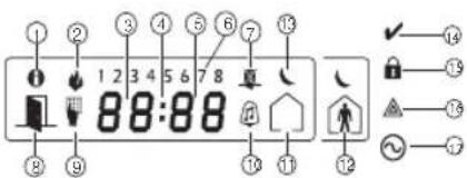
| 1 | Memory - Indicates that alarms are in memory. | 10 | Chime Turns on when Door Chime is enabled and off when Door Chime is disabled. |
| 2 | Fire - Indicates that fire alarms are in memory. | 11 | Away - Indicates that the panel is armed in away mode. |
| 3,4,5 | Clock Digits - These digits indicate the hour and minutes when the local clock is active! and also identify the zone when the OPEN or ALARM icons are active. These digits scroll one zone per second from the lowest zone number to the highest when scrolling through zones. | 12 | Stay - Indicates that the panel is armed in stay mode. |
| 13 | Night - Indicates that the panel is armed in night mode. | ||
| 6ants | 1 to 8 - These numbers display toggles or digits in binary while they are needed. | 14 | Ready Light (green) - If the Ready light is on, the system is ready for arming. |
| 7LCD review | Bypass Indicates that there are zones automatically or manually bypassed. | 15 | Armed Light (red) - If the Armed light is on, the system has been armed successfully. |
| setting e8 fun | Open - When zones are opened this icon will turn on and the open zones are displayed. | 16 | System Trouble - Indicates that a system trouble is active. |
| 9 | Program - If the system is in Installer's or User's Pro- gramming, or the keypad is busy, this icon flashes. If an access code is required while accessing star menus, this LED is on steadily to indicate that the code is required. | 17 | AC - Indicates that AC is present at the main panel. |
Troubleshooting
- When attempting to assign a zone number to a wireless device, the keypad responds with a long beep.
- Ensure that the keypad is properly connected to the Corbus.
- After entering the ESN of a wireless device, then tripping it, the keypad does not indicate the zone is open.
Ensure the ESN has been entered correctly. - Ensure that the zone is enabled for the partition (if partition programming is used).
Table 16: Word Library
| Item Text | Item Text | Item Text | Item Text | Item Text | |||||||||
| 001 | Aborted | 037 | Closed | 073 | Feature | 109 | Library | 143 | Pool | 181 | Tamper | 217 | N |
| 002 | AC | 038 | Closet | 074 | Fence | 110 | Light | 146 | Porch | 182 | Temperature | 218 | O |
| 003 | Access | 039 | Closing | 075 | Fire | 111 | Lights | 147 | Power | 183 | Test | 219 | P |
| 004 | Active | 040 | Code | 076 | First | 112 | Living | 148 | Process | 184 | Time | 220 | Q |
| 005 | Activity | 041 | Communicator | 077 | Floor | 113 | Load | 149 | Program | 185 | To | 221 | R |
| 006 | Alarm | 042 | Computer | 078 | Force | 111 | Loading | 150 | Progress | 186 | Touchpad | 222 | S |
| 007 | All | 043 | Control | 079 | Fuyer | 115 | Low | 151 | Quiet | 187 | Trouble | 223 | T |
| 008 | AM | 044 | Date | 080 | Freeze | 116 | Lower | 152 | Rear | 188 | Unbypass | 224 | U |
| 009 | Area | 045 | Daughter's | 081 | Front | 117 | Main | 153 | Receiver | 189 | Unit | 225 | V |
| 010 | Arm | 046 | Degrees | 082 | Furnace | 118 | Master | 154 | Report | 190 | Up | 226 | W |
| 011 | Armed | 047 | Delay | 083 | Gallery | 119 | Mat | 155 | RF | 191 | West | 227 | X |
| 012 | Arming | 048 | Den | 084 | Gamage | 120 | Medical | 156 | Right | 192 | Window | 228 | Y |
| 013 | Attic | 049 | Desk | 085 | Gas | 121 | Memory | 157 | Room | 193 | Zone | 229 | Z |
| 014 | Auxiliary | 050 | Detector | 086 | Glass | 122 | Menu | 158 | Safe | 194 | 0 | 230 | Space |
| 015 | Away | 051 | Dining | 087 | Goodbye | 123 | Monoxide | 159 | Saver | 195 | 1 | 231 | , |
| 016 | Baby | 052 | Disarmed | 088 | Cym | 124 | Mother's | 160 | Schedule | 196 | 2 | 232 | - |
| 017 | Bank | 053 | Door | 089 | Hallway | 125 | Mutter | 161 | Screen | 197 | 3 | 233 | - |
| 018 | Bar | 054 | Down | 090 | Heat | 126 | No | 162 | Second | 198 | 4 | 234 | * |
| 019 | Basement | 055 | Download | 091 | Hello | 127 | North | 163 | Sensor | 199 | 5 | 235 | # |
| 020 | Bathroom | 056 | Downstairs | 092 | Help | 128 | Not | 164 | Service | 200 | 6 | 236 | : |
| 021 | Battery | 057 | Drawer | 093 | High | 129 | Now | 165 | Shed | 201 | 7 | 237 | / |
| 022 | Bedroom | 058 | Driveway | 094 | Home | 130 | Number | 166 | Shock | 202 | 8 | 238 | ? |
| 023 | Bonus | 059 | Duct | 095 | House | 131 | Off | 167 | Shop | 203 | 9 | ||
| 024 | Bottom | 060 | Dress | 096 | In | 132 | Office | 168 | Side | 204 | A | ||
| 025 | Brewzeway | 061 | East | 097 | Install | 133 | OK | 169 | Siren | 205 | B | ||
| 026 | Building | 062 | Energy | 098 | Interior | 134 | On | 170 | Sliding | 206 | C | ||
| 027 | Bus | 068 | Enter | 099 | Interession | 135 | Open | 171 | Smoke | 207 | D | ||
| 028 | Bypass | 064 | Entry | 100 | Invalid | 136 | Opening | 172 | Son's | 208 | E | ||
| 029 | Bypassed | 065 | Error | 101 | Is | 137 | Panic | 173 | Sound | 209 | F | ||
| 030 | Cabinet | 066 | Exercise | 102 | Key | 138 | Partition | 174 | South | 210 | G | ||
| 031 | Camera | 067 | Exit | 103 | Kids | 139 | Patio | 175 | Special | 211 | H | ||
| 032 | Canceled | 068 | Exterior | 104 | Kitchen | 140 | Pet | 176 | Stairs | 212 | I | ||
| 033 | Car | 069 | Factory | 105 | Latchkey | 141 | Phone | 177 | Stay | 213 | J | ||
| 034 | Carbam | 070 | Failure | 106 | Laundry | 142 | Please | 178 | Sun | 214 | K | ||
| 035 | Central | 071 | Family | 107 | Left | 143 | PM | 179 | Supervisory | 215 | L | ||
| 036 | Chime | 072 | Father's | 108 | Level | 144 | Police | 180 | System | 216 | M |
Limited Warranty
(b)Separation of Components - The Software Product is licensed as a single product WARLABFand Corp for a 100% SUSH. FOR IT ANY OTHER WARRANTY OR LIABILITY beeseparal-fawuueeopemtheneoHARDWARE unit THIS SOFTWARE PRODUCT
Digital SecurityContrats (DS) warrants that 10f12 months thredal of pure prnprprrneprrnreernerHAROWA unit. freef defects materialsandworkmanship under normal use andthful intuiflnty beacfted htnr nIgTINTEGRATED PRODUCT - If you acquired this SOFTWARE with HARDWARE as a single integrated product is licensed with the SOFTWARE as a single integrated product, please refer to the following information: SOFTWARE as a single integrated product. Any other legal theory such damages include but are not necessarily caused by the software or products used in the application.
t h
The 100000000000000000000000000000000000000000000000000000000000000000000000000000000000000
P 101058
ciated media, printedmaterals, and online preectronic documentation. DSC anditsuppliers.
Any softwareprovidsdalongwithSoftwareProductthatisassociatedwithaseparateond-userlicnREXORSTRcNSTRcions-Youagree Youwillnotexportcre-export the SsT 380100000000000000000000000000000000000000000000000000000000000000000000000000000000000000000000
T 1. GRANT OF LICENSEE This EULA grantsYouthfollowingrights: OPERATION OF THE SOFTWARE WILL BE UNINTERRUPTED ERROR-FREE. ATTENTION: Cemanual conteddesinformations surerestrictions concantant le fonctionemenonPRODUCTION INSTALLED.
10
2.DESCRIPTION OF OTHER RIGHTS AND LIMITATIONS
a) Limitations on Reversal Engineering, Discompensation and Disassembly. You may not reverse the product or service contract. This WARRANTY CONTAINS THE ENTIRE WARRANTY COGNITIVE SERVICE CONTRACTS. LIMITATIONS ON THIS WARRANTY DO NOT APPLY TO ALL OTHER WARRANTYING PROPERTIES.
OTHER PERSON PURPORTING TO ACT ON ITS BEHALF TO MODIFY OR TO CHANGE THIS
Introduction- Francais
Courant absorbé HS2LED/HS21CN(P)/HS2LCD(P)/HS21CNRF (P)/IIS2LCDRF(P):55mA(min/105mA(max)
Dimensions (H x 1 x P): 168mm x 122mm x 20 mm
Poids: 260g
868 MHz (HS21CNRF8/HS2LCDRF8)
912-919 MHz (HS2ICNRF9/HS2LCDF9)
128 zones sans fil max
1 contact anti-sabotage 1 contact anti-sabotage
(HS2ICNRF(P)x/HS2LCDRF(P)x)
HS2LFD/HS21CN(P)/HS2LCDP)/HS2ICNRF(P)/HS2LCDRF(P) Consumo de corriente:55mA(min)/105mA(max.)
AS EN LOTE,ER DISPOSION
ER DISPOSITION
CAGADIENSES
CANADIENSES
JUSION O
NTAES.1AS
1.4.2.2.2.1
- Selective amino acids as epigates of progr a).
[860] Nstreamo da ranhura do teclado
[13] - Armar Total [31] - Ativar PGM Global Local
[02] - Armar Presente Ins- [14] - Desarmar Gla [32] - Modo Omitir tantanto
[03] - Armar Modo Present [16] - [^*][0] Saida [33] - Omitir Rccha-
(HS2ICNRF(P)x/HS2LCDRF(P)x)

- HS2LED/HS2ICON(P)(RF)X/HS2LCD(RF)(P)X V1.3
- Introduction
- Specifications
- Unpack
- HS2LED/ICN(RF)/LCD(RF) HS2ICN(RF)P/LCD(RF)P
- Mount the Keypad
- Disassemble Keypad
- Mount and Wire Keypad
- Wiring
- Apply Power
- program the Keypad
- Language Programming
- Enroll the Keypad
- [902][000] Auto Enroll
- [902][001] Manual Enroll
- [902][002] - Module Slot Assignment (LED, ICON)
- [902][003] - Module Slot Assignment (LCD
- [902][101] Unenroll Keypads
- [903][101] Confirm Keypad
- Assign a Partition to the Keypad
- Program Labels (LCD keypads)
- er the number 2 . Press [ ] , then scrol to Save . Press [ ] agto save the label . To delete a character use the [<] keys to movs the
- Ding Keypad Programming
- [860] Keypad Slot Number
- [861]-[876] Keypad Programming Sections
- [809] Address of Partition
- [001]-[005] Keypad Function Key Programming
- Keypad Function Keys
- [011] Keypad Input/Output Programming Zone /PGM Number Default 000 |
- [021] First Keypad Options
- [022] Second Keypad Options
- [023] Third Keypad Options
- [030] Downloaded LCD Message
- [031] Downloaded LCD Message Duration
- [041] Indoor Temperature Zone Assignment Default: 000 | (Valid entries are 000-128)
- [042] Outdoor Temperature Zone Assignmer
- [101]-[228] Door Chime for Zones
- [991] Reset Keypad Programming to Facto Defaults
- Proximity (Prox) Tags Support (HS2ICNP/HS2ICNRFP/HS2LCDP)
- Assign Proximity Tags
- Delete Proximity Tags
- LED Bar
- Downloading
- Wireless Device Setup and Programming
- (HS21CNRF(P)x/HS2LCDRF(P)x)
- [804][000] Enroll Wireless Devices
- [804][001]-[716] Wireless De
- [804][801] RF Jam Detect
- [804][802] Wireless Supervision Window
- [804][810] Wireless Option 1
- [804][841] Visual Verification Programming
- [804][901]-[905] Delete Wireless Devices
- [604][921]-[925] Replace Wireless Devices
- [804][990][001- 005] Show All Devices
- [904] Placement Testing Wireless Devices keypads only)
- Keypad Symbols
- Troubleshooting
- Limited Warranty
- Introduction- Francais
- (HS2ICNRF(P)x/HS2LCDRF(P)x)
Brand : DSC
Model : HS2LCDWFP9
Category : Security and Access Control System