
KLHW26 - Television SONY - Free user manual and instructions
Find the device manual for free KLHW26 SONY in PDF.
| Product Type | LCD Television |
| Brand | Sony |
| Model | KLHW26 |
| Screen Size | 26 inches (diagonal 660 mm) |
| Resolution | 1366 × 768 pixels |
| Dimensions (W × H × D) | 663 × 505 × 220 mm |
| Weight | 13.5 kg |
| Power Supply | 100-240 V AC, 50/60 Hz, 1.2 A |
| Power Consumption | 110 W |
| Video Inputs | HD15 (RGB/COMPONENT), HDMI 1, HDMI 2, OPTION |
| Audio Input | Stereo mini-jack (COMMON AUDIO IN) |
| Audio Output | Built-in speakers 10 W + 10 W |
| Main Functions | Cinema Mode, ECO Mode, Standby, remote control, picture and sound settings |
| Screen Maintenance | Soft dry cloth. Do not use alcohol, gasoline, or thinner. |
| Safety | Do not open the chassis. Avoid rain and humidity. Use an appropriate power cord. |
| Supplied Accessories | Power cord, remote control RM-YA004, AA batteries (2), cable holder, instruction manual |
| Options | BKM-FW series adapters for expansion |
| Repairability | Refer to qualified technician. Self-diagnosis by STANDBY LED flashing. |
Frequently Asked Questions - KLHW26 SONY
User questions about KLHW26 SONY
0 question about this device. Answer the ones you know or ask your own.
Ask a new question about this device
Download the instructions for your Television in PDF format for free! Find your manual KLHW26 - SONY and take your electronic device back in hand. On this page are published all the documents necessary for the use of your device. KLHW26 by SONY.
USER MANUAL KLHW26 SONY
Flat Wide Display Monitor
取拔説明書 JP
Operating Instructions GB
Mode d'emploi FR
12-12-12-12-12-12-12-12-12-12-12-12-12-12-12-12-12-12-12-12-12-12-12-12-12-12-12-12-12-12-12-12-12-12-
http://www.sony.net/
Sony Corporation Printed in China
SRS(●) BBE ●WOW DIGITAL
© 2006 Sony Corporation
安全のたてに
KLH-W26:663×505×220 mm
13、14 15.16.17.18.19.20.21.22.23.24.25.26.27.28.29.30.31.32.33.34.35.36.37.38.39.40.41.42.43.44.45.46.47.48.49.50.51.52.53.54.55.56.57.58.59.60.61.62.63.64.65.66.67.68.69.70.71.72.73.74.75.76.77.78.79.80.81.82.83.84.85.86.87.88.89.90.91.92.93.94.95.96.97.98.99.00
安全規格電安法、VCCI 标本B
Manual (IP Address Setup)
28
MENU 10.15
MUTING 15
N
The model and serial numbers are located on the rear. Record the model and serial numbers in the spaces provided below. Refer to these numbers whenever you call upon your Sony dealer regarding this product.
Model No. _ Serial No. _
To reduce the risk of fire or electric shock, do not expose this apparatus to rain or moisture.
To avoid electrical shock, do not open the cabinet. Refer servicing to qualified personnel only.
On transportation
When you carry the display unit, hold the unit itself, not the speakers. If you fail to do so, the speakers may come out of the unit and the unit may fall. This can cause injury.
For customers in the U.S.A.
If you have any questions about this product, you may call; Sony Customer Information Services Center 1-800-222-7669 or http://www.sony.com/
Declaration of Conformity
Trade Name: SONY
Model: KLH-W26/KLH-W32
Responsible Party: Sony Electronics Inc.
Address: 16530 Via Esprillo, San
Diego, CA 92127 U.S.A.
Telephone Number: 858-942-2230
This device complies with Part 15 of the FCC Rules. Operation is subject to the following two conditions: (1) This device may not cause harmful interference, and (2) this device must accept any interference received, including interference that may cause undesired operation.
This equipment has been tested and found to comply with the limits for a Class B digital device, pursuant to Part 15 of the FCC Rules. These limits are designed to provide reasonable protection against harmful interference in a residential installation. This equipment generates, uses, and can radiate radio frequency energy and, if not installed and used in accordance with the instructions, may cause harmful interference to radio communications. However, there is no guarantee that interference will not occur in a particular installation. If this equipment does cause
harmful interference to radio or television reception, which can be determined by turning the equipment off and on, the user is encouraged to try to correct the interference by one or more of the following measures:
- Reorient or relocate the receiving antenna.
- Increase the separation between the equipment and receiver.
- Connect the equipment into an outlet on a circuit different from that to which the receiver is connected.
- Consult the dealer or an experienced radio/TV technician for help.
You are cautioned that any changes or modifications not expressly approved in this manual could void your authority to operate this equipment.
For customers in Canada
This class B digital apparatus complies with Canadian ICES-003.
The socket-outlet should be installed near the equipment and be easily accessible.
CAUTION
RISK OF EXPLOSION IF BATTERY IS REPLACED BY AN INCORRECT TYPE. DISPOSE OF USED BATTERIES ACCORDING TO THE LOCAL RULES
Trademark Information
WOW, SRS and (symbol are trademarks of SRS Labs, Inc. WOW technology is incorporated under license from SRS Labs, Inc.
Manufactured under license from BBE Sound, Inc. Licensed by BBE Sound, Inc. under one or more of the following US patents: 5510752, 5736897. BBE and BBE symbol are registered trademarks of BBE Sound, Inc.
Table of Contents
Introduction
Precautions 4
Recommendations on Installation 6
Location and Function of Parts and Controls
Front Panel. 7
Side Panel. 8
Optional Adaptors 9
Rear Panel 10
Remote Control 11
Button Description 11
Special Buttons on the Remote Control 13
Using the Wide Mode. 13
Using the Sleep Function. 14
Using the ECO Mode Function 14
Connections
Connecting the AC Power Cord and Arranging the Input Cables 15
Using the Settings
Overview of the Menus 16
Picture Settings 18
Sound Settings 20
Screen Settings 21
Setup Settings 24
Other Information
Troubleshooting 26
Input Signal Reference Chart 27
Specifications 28
Index 30
Introduction
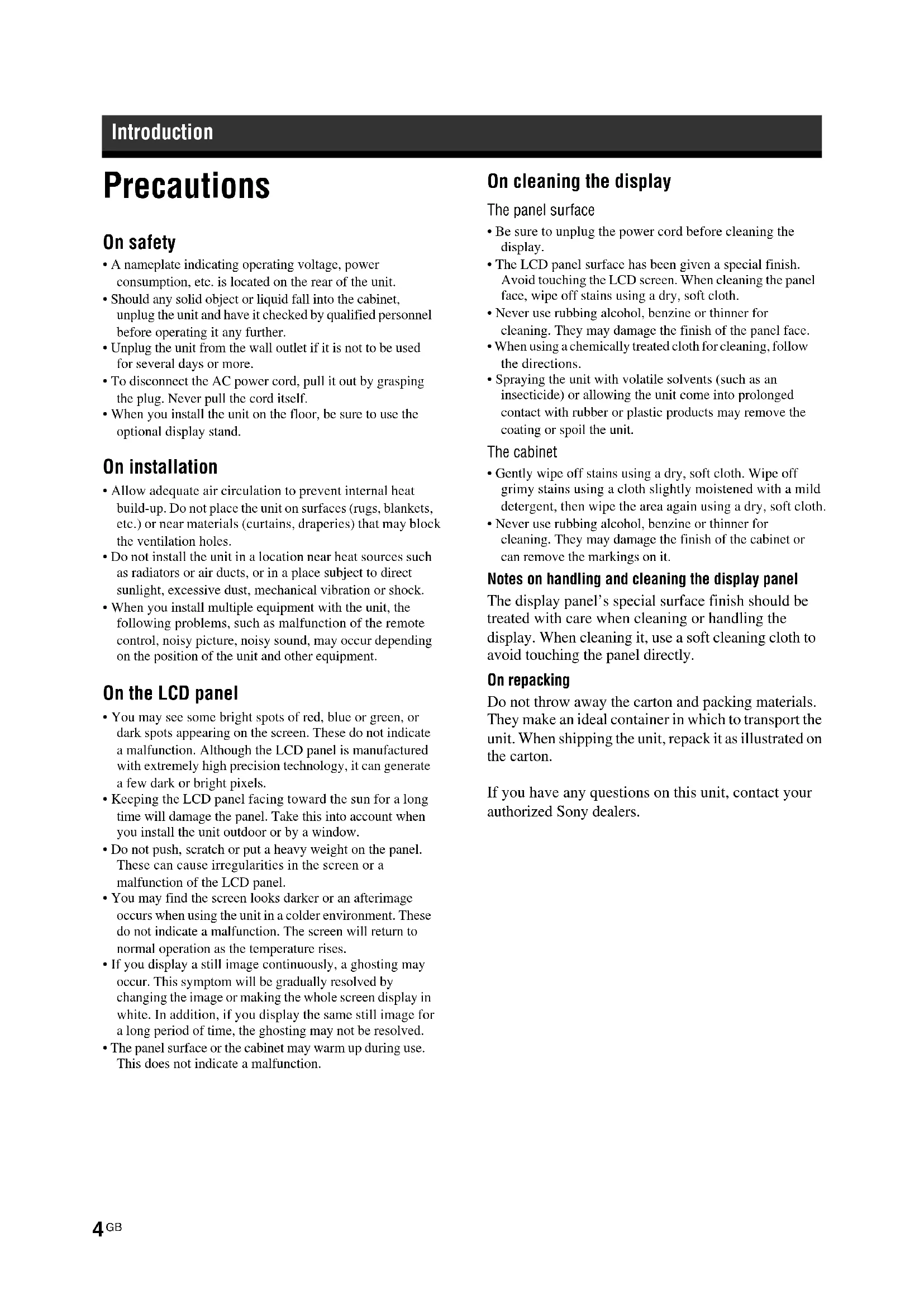
Precautions
On safety
- A nameplate indicating operating voltage, power consumption, etc. is located on the rear of the unit.
- Should any solid object or liquid fall into the cabinet, unplug the unit and have it checked by qualified personnel before operating it any further.
- Unplug the unit from the wall outlet if it is not to be used for several days or more.
- To disconnect the AC power cord, pull it out by grasping the plug. Never pull the cord itself.
- When you install the unit on the floor, be sure to use the optional display stand.
On installation
- Allow adequate air circulation to prevent internal heat build-up. Do not place the unit on surfaces (rugs, blankets, etc.) or near materials (curtains, draperies) that may block the ventilation holes.
- Do not install the unit in a location near heat sources such as radiators or air ducts, or in a place subject to direct sunlight, excessive dust, mechanical vibration or shock.
- When you install multiple equipment with the unit, the following problems, such as malfunction of the remote control, noisy picture, noisy sound, may occur depending on the position of the unit and other equipment.
On the LCD panel
- You may see some bright spots of red, blue or green, or dark spots appearing on the screen. These do not indicate a malfunction. Although the LCD panel is manufactured with extremely high precision technology, it can generate a few dark or bright pixels.
- Keeping the LCD panel facing toward the sun for a long time will damage the panel. Take this into account when you install the unit outdoor or by a window.
- Do not push, scratch or put a heavy weight on the panel. These can cause irregularities in the screen or a malfunction of the LCD panel.
- You may find the screen looks darker or an afterimage occurs when using the unit in a colder environment. These do not indicate a malfunction. The screen will return to normal operation as the temperature rises.
- If you display a still image continuously, a ghosting may occur. This symptom will be gradually resolved by changing the image or making the whole screen display in white. In addition, if you display the same still image for a long period of time, the ghosting may not be resolved.
- The panel surface or the cabinet may warm up during use. This does not indicate a malfunction.
On cleaning the display
The panel surface
- Be sure to unplug the power cord before cleaning the display.
- The LCD panel surface has been given a special finish. Avoid touching the LCD screen. When cleaning the panel face, wipe off stains using a dry, soft cloth.
- Never use rubbing alcohol, benzine or thinner for cleaning. They may damage the finish of the panel face.
- When using a chemically treated cloth for cleaning, follow the directions.
- Spraying the unit with volatile solvents (such as an insecticide) or allowing the unit come into prolonged contact with rubber or plastic products may remove the coating or spoil the unit.
The cabinet
- Gently wipe off stains using a dry, soft cloth. Wipe off grimy stains using a cloth slightly moistened with a mild detergent, then wipe the area again using a dry, soft cloth.
- Never use rubbing alcohol, benzine or thinner for cleaning. They may damage the finish of the cabinet or can remove the markings on it.
Notes on handling and cleaning the display panel
The display panel's special surface finish should be treated with care when cleaning or handling the display. When cleaning it, use a soft cleaning cloth to avoid touching the panel directly.
On repacking
Do not throw away the carton and packing materials. They make an ideal container in which to transport the unit. When shipping the unit, repack it as illustrated on the carton.
If you have any questions on this unit, contact your authorized Sony dealers.
Disposal of Waste Electrical and Electronic Equipment for business use (Applicable in the European Union and other European countries with separate collection systems)


This symbol on the product or on its packaging indicates that this product shall not be treated as household waste. Instead it shall be handed over to the applicable take-back scheme for the recycling of electrical and electronic equipment. By ensuring this product is disposed of correctly, you will help prevent potential negative
consequences for the environment and human health, which could otherwise be caused by inappropriate waste handling of this product. The recycling of materials will help to conserve natural resources. For more detailed information about recycling of this product, please contact your local Sony office or visit Sony Europe's web site for business customers: http://www.sonybiz.net/environment
For the State of California, USA only
Perchlorate Material - special handling may apply, See www.dtsc.ca.gov/hazardouswaste/perchlorate Perchlorate Material : Lithium battery contains perchlorate.
For Customers in the United States
Lamp in this product contains mercury. Disposal of these materials may be regulated due to environmental considerations. For disposal or recycling information, please contact your local authorities or the Electronic Industries Alliance (www.eiae.org).
For Customers in Taiwan only
廢電池請回收

Warning on power connection
Use the proper power cord for your local power supply.
| United States, Canada | Continental Europe | United Kingdom, Ireland, Australia, New Zealand | Japan | ||
| Plug type VM0233 COX | 07 636 — | a) | VM1296 | ||
| Female end VM0089 COX | X-02 VM0310B VM | M0303B VM | 313 | ||
| Cord type SVT H05VV-F | CEE (13) 53rd (Q.C) HVCTF | ||||
| Minimum cord set rating | 10A/125V 10A/250V 10A/250V | 10A/125V | |||
| Safety approval | UL/CSA | VDE VDE | DENAN-HO | ||
a) Note: Use an appropriate rating plug which complies with local regulations.
Recommendations on Installation
Provide an ample amount of space around the display
- To prevent internal heat buildup from scaling off the display, make sure to ensure proper ventilation by leaving open the minimum amount of space around the display, as illustrated below.
The ambient temperature must be 0 ^ C to 35^ (32°F to 95^) - Regarding the installation of hardware such as brackets, screws, or bolts, we cannot specify the products. Actual installation is up to the authorized local dealers. Consult with qualified Sony personnel for installation.
- While the display is on, a certain amount of heat builds up inside. This can cause burns. Avoid touching the top or rear of the display when it is powered on or just after it has entered standby mode.
Front
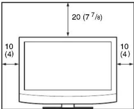
Side
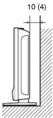
Units: cm (inches)
Location and Function of Parts and Controls
Front Panel
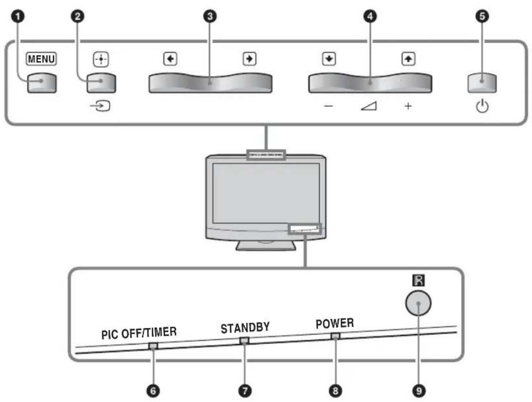
1 MENU (page 16)
2/ + (INPUT)
- In the menu screen, this button works as the "Set" button.
- This button works to switch the input signal when it is not in the menu screen.
Selects an input signal from among the HD15/HDMI 1/HDMI 2/OPTION connectors.
When an optional adaptor is not installed in the OPTION slot, OPTION will be skipped.
3/ +
In the menu screen, these buttons work as left/right buttons
4/
- Increases (+) or decreases (-) the volume.
- In the menu screen, these buttons work as up/down buttons (

Switches the display on/off (standby).
Note
To protect the panel, a certain amount of time is required to turn the display to on/off (standby). When you turn the display on again, soon after turning it off, wait about 5 seconds before you turn it on again.
⑥ PIC OFF/TIMER indicator
- Lights up in green when "Picture Off" function of "ECO Mode" is selected.
- Lights up in orange when "Sleep Timer" function is activated.
7STANDBYindicator
Lights up in red when the display is in standby mode.
3 POWER indicator
Lights up in green when the display is switched on.
9R note control sensor
Side Panel
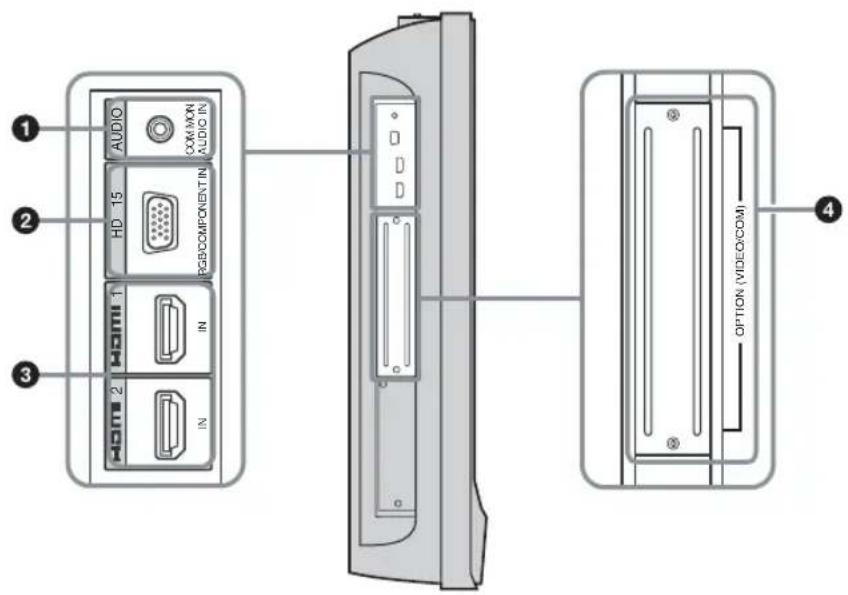
| Connector Description | |
| 1 AUDIO (COMMON AUDIO IN) (Stereo mini jack) | Inputs an audio signal. Connects to the audio signal output of a piece of video equipment or PC. Supports audio signals corresponding to 2 and 3. |
| 2 HD15 (RGB/COMPONENT IN)(D-sub 15-pin) | Connects to the analog RGB signal or component signal output of a piece of video equipment or PC. See page 29.NoteWhen inputting a component signal, be sure not to input sync signals to pins 13 and 14. If you do so, the picture may not be displayed properly. |
| 3 HDMI 1/HDMI 2 IN | HDMI (High-Definition Multimedia Interface) provides an interface between the display and any HDMI-equipped audio/video equipment, as well as PC. You can enjoy enhanced or high-definition video, and two-channel digital audio. You can also connect a piece of DVI-equipped equipment to your display by using an HDMI-to-DVI cable (not supplied). The appropriate mode for a piece of audio/video equipment or PC is automatically selected in accordance with the connected equipment.NoteBe sure to use only an HDMI cable that bears the HDMI logo. |
| 4 OPTION slot(VIDEO/COM port) | This slot supports video signals and communication functions. By installing an optional adaptor (the BKM-FW series) in this slot, you can expand the input signal connectors or control the display via the network. |
Optional Adaptors
The connectors marked with 4 on the side panel are slot-in type and can be installed with any of the optional adaptors (not supplied).
For details on installation, consult your Sony dealers.
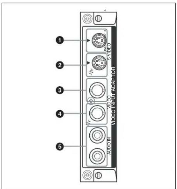
VIDEO INPUT Adaptor BKM-FW10
SVIDEO IN (Mini DIN 4-pin): Connects to the S Video signal output of a piece of video equipment.
2SVIDEO OUT (Mini DIN 4-pin): Connects to the S Video signal input of a piece of video equipment.
VIDEO IN (BNC): Connects to the video signal output of a piece of video equipment.
VIDEO OUT (BNC): Connects to the video signal input of a piece of video equipment.
AUDIO IN L/R (Pin jack): Connects to the audio output of a piece of video equipment.
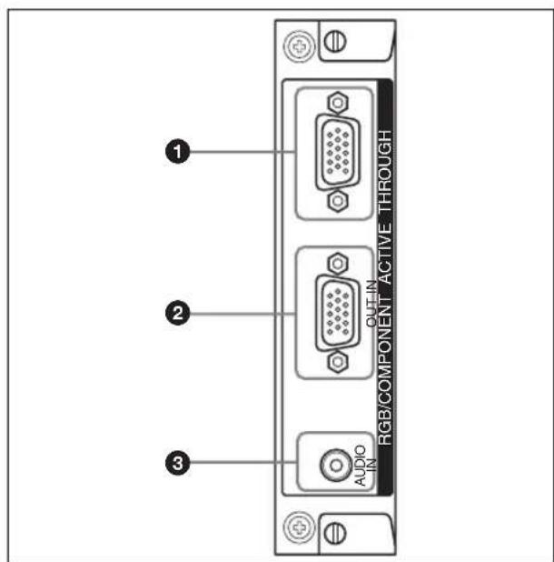
RGB/COMPONENT ACTIVE THROUGH Adaptor BKM-FW12
RGB/COMPONENT IN (D-sub 15-pin):
Connects to the component signal output or analog RGB signal output of a piece of video equipment or PC. For details on inputting a component signal to the connector, see Pin assignment on page 29.
Note
When inputting a component signal, be sure not to input sync signals to pins 13 and 14. If you do so, the picture may not be displayed properly.
RGB/COMPONENT OUT (D-sub 15-pin):
Connects to the component signal input or analog RGB signal input of a piece of video equipment or PC.
Inputs an audio signal. Connects to the audio signal output of a piece of video equipment or PC.
Note
When the display is not connected to an AC power or is in the standby mode, no signal is output from the RGB/COMPONENT OUT.
For details on the optional adaptors for system expansion, BKM-FW series, see each instruction manual.
Rear Panel

Parts Description
| 1 AC IN socket | Connect the supplied AC power cord to this socket and to a wall outlet. Once you connect the AC power cord, the STANDBY indicator lights up in red and the display goes into the standby mode. See page 15. |
| 2 Stand attachment hole | Use this hole to secure the display on a table, etc. using an M6 screw. |
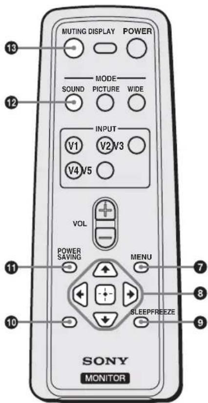
Remote Control
Button Description
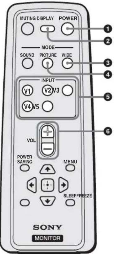
1 POWER button
Press to switch the display on/off (standby).
DISPLAY button
Press to display the currently selected input signal information and the "Wide Mode" setting on the screen. Press again to hide them. If this displayed information is left undisturbed for a short time, it will disappear automatically. If "Sleep Timer" is set, the remaining time for "Sleep Timer" can be displayed by pressing DISPLAY button.
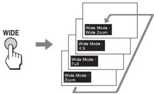
WIDE button
Press to change the aspect ratio in "Wide Mode". See page 13.
4PICTURE button
Selects "Picture Mode". Each press toggles between "Vivid", "Standard", and "Custom".
INPUT V1-V5 buttons
Press the following buttons to select an input signal from the equipment connected to input connectors.
- V1 button: HD15 (The RGB signal or component signal is selected automatically in accordance with the connected equipment.)
V2 button: HDMI 1
V3 button: HDMI 2
- V4 button: OPTION (When an optional adaptor is installed.)
V5 button: Not for use.
6VOL + / - button
Press to adjust the volume.
Tip
The VOL + button has a tactile dot. Use it as a reference when operating the display.
Note
Insert two size AA (R6) batteries (supplied) by matching the and on the batteries to the diagram inside the remote control's battery compartment.

7 MENU button
Press to show menus. Press again to hide them. See page 16.
3 / / / / buttons
The / / buttons move the menu cursor (yellow) and set values, etc. Pressing sets the selected menu or setting items.
SLEEP button
Press repeatedly until the display shows the time in minutes (15, 30, 45, 60, 90 or 120) that you want the display to remain on before shutting off. To cancel "Sleep Timer", press SLEEP button repeatedly until "Sleep Timer: Off" appears.
10FREEZE button
Not for use.
POWERSAVINGbutton
Changes the options of "ECO Mode". Press to save the power consumption by changing the backlight brightness. Select from "Off", "Low", "High" or "Picture Off". See page 14.
12 SOUND button
Selects "Sound Mode". Each press toggles between "Dynamic", "Standard", "SRS WOW", and "Custom".
3MUTING button
Press to mute the sound. Press again to restore sound.
Special Buttons on the Remote Control
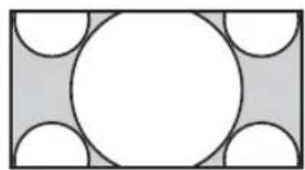
Using the Wide Mode
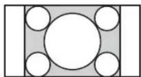
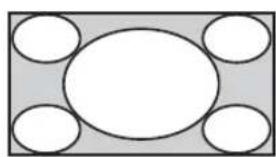
You can change the aspect ratio of the screen by using the "Wide Mode".
Tip
You can also access the "Wide Mode" settings in the "Screen" settings. See page 21, 23.
For Video, DVD or HDMI Input (other than PC input)
4:3 Original Source
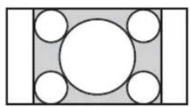

Wide Zoom

4:3
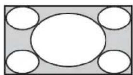
Full
Zoom
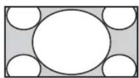
16:9 Original Source
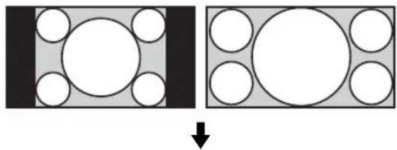
Wide Zoom
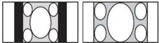
4:3
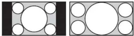
Full
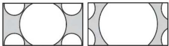
Zoom
Note
When the input signal is 1080i, 720p, or 1080p, "Wide Zoom" and "4:3" cannot be selected. See page 21.
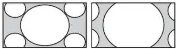
For PC Input
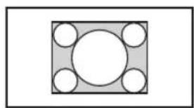
Normal
Full 1
Full 2
Using the Sleep Function
You can set the display to turn off automatically after a predetermined period of time (15, 30, 45, 60, 90 or 120 minutes).

While "Sleep Timer" is activated, the PIC OFF/ TIMER indicator on the display lights up in orange.
To cancel Sleep Timer
Press SLEEP repeatedly until "Sleep Timer : Off" appears or turn the display power to off then turn on the display again.
Notes
- If you turn the display off, and then turn it on again, "Sleep Timer" returns to "Sleep Timer: Off".
"Sleep Timer - power down" appears one minute before the display shuts off. This message may not appear if you are performing other operations in the settings. - You can set "Sleep Timer" to on using the "Setup" settings. Select "Sleep Timer" in the "Setup" settings, then set it to "15 min", "30 min", "45 min", "60 min", "90 min", or "120min".
- While "Sleep Timer" is activated, if you press SLEEP once, the time remaining until the display shuts off will be displayed.
Using the ECO Mode Function
You can reduce the power consumption of the display.
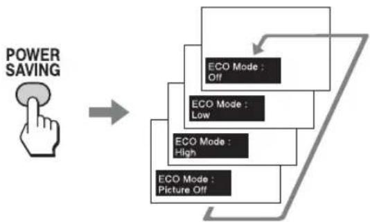
To cancel the ECO Mode
Press POWER SAVING button repeatedly until "ECO Mode : Off" appears.
Notes
- If you turn off the display when the "ECO Mode" is activated, the mode stays on next time you turn on the display except "Picture Off".
- You can set the "ECO Mode" using the "Setup" settings. Select "ECO Mode" in the "Setup" settings, then set it to "Off", "Low", "High", or "Picture Off".
Connections
Before you start
- First make sure that the power of each piece of equipment is turned off.
- Use cables suitable for the equipment to be connected.
- Connect the cables, fully inserting them into the connectors or jacks. A loose connection may cause hum and other noise.
- To disconnect the cable, pull it out by grasping the plug. Never pull the cable itself.
See the instruction manual of the equipment to be connected, too. - Insert the plug securely into the AC IN socket.
Connecting the AC Power Cord and Arranging the Input Cables
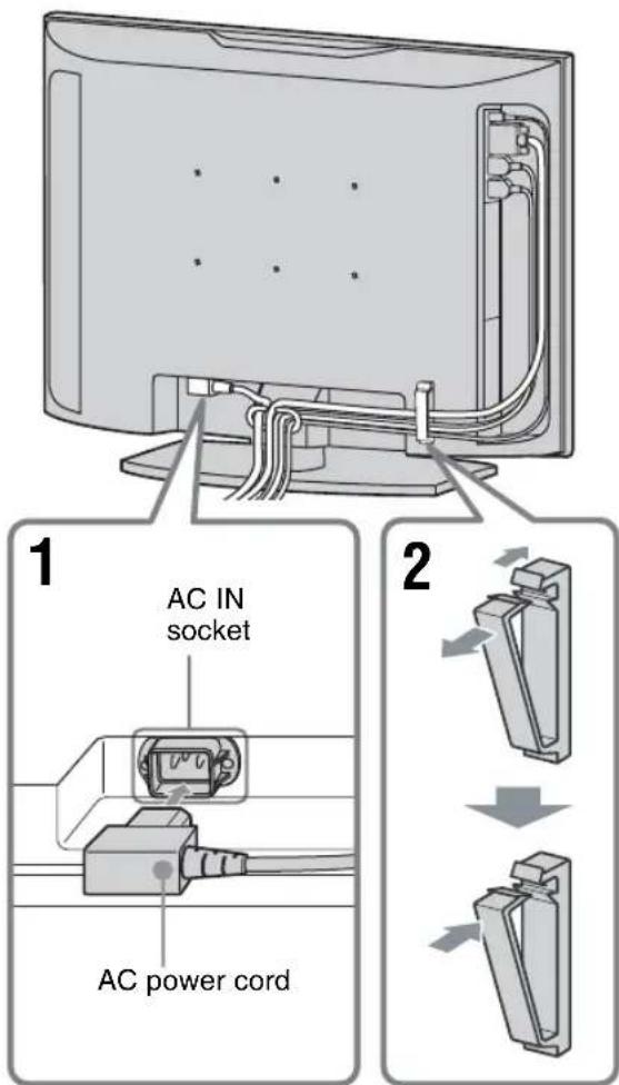
1 Insert the AC power cord into the AC IN socket on the bottom.
2 Use the cable holder to arrange the connected cables, as shown in the figure.
Using the Settings
Overview of the Menus

1 Press MENU button.
2 Press / to highlight the desired menu icon.
3 Press + or To exit the menu, press MENU button.
To change the on-screen language
Select the desired language for on-screen settings and messages from "English", "Espanol", "Français", "Italiano", "Deutsch" or "日本語" "English" (English) is set for the default setting. See page 24.
The settings provide you access to the following features:
Settings Allows you to set/change
Picture
Picture Mode (page 18, 19)
Picture Mode Reset (page 18, 19)
Picture (page 18, 19)
Brightness (page 18, 19)
Color (page 18)
Hue (page 18)
Color Temp. (page 18, 19)
Sharpness (page 18)
Noise Reduction (page 18)
CineMotion (page 18)
Sound
Sound Mode (page 20)
Sound Mode Reset (page 20)
Treble (page 20)
Bass (page 20)
Balance (page 20)
Common Audio Sel. (page 20)
Speaker Out (page 20)
Settings Allows you to set/change
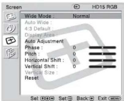
Screen
Wide Mode (page 21, 23)
Auto Wide (page 21)
4:3 Default (page 22)
Display Area (page 22)
Auto Adjustment (page 23)
Phase (page 23)
Pitch (page 23)
Horizontal Shift (page 22, 23)
Vertical Shift (page 22, 23)
Vertical Size (page 22)
Reset (page 22, 23)
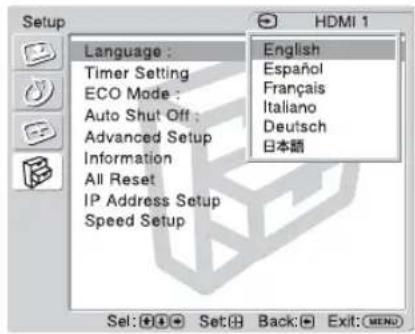
Setup
Language (page 24)
Timer Setting (page 24)
ECO Mode (page 24)
Auto Shut Off (page 24)
Advanced Setup (page 24)
Information (page 25)
All Reset (page 25)
IP Address Setup (page 25)
Speed Setup (page 25)
- Menu icons displayed at the bottom of the screen may not work, depending on the settings.

Picture Settings
For Video Input
To highlight an option and to change settings, press

Press to confirm the selection.
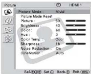
The "Picture" settings include the following options:
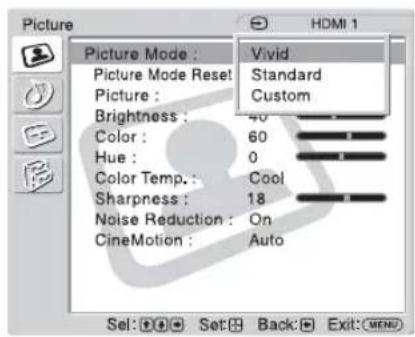
Picture Mode
"Vivid": Select for enhanced picture contrast and sharpness.
"Standard": Select for standard picture settings.
"Custom": Allows you to store preferred settings.
Tips
- To change from one "Picture Mode" option to another, you can also use PICTURE on the remote control instead.
- You can alter the "Picture Mode" options for each input.
Picture Mode Reset
Resetssall settings and adjustments currently selected in "Picture Mode"(Vivid",
"Standard", "Custom") to the default setting (except for the options grayed out).
Picture
Adjust to increase or decrease picture contrast.
Brightness
Adjust to brighten or darken the picture.
Color
Adjust to increase or decrease color intensity.
Hue
Adjusts the color tones of the picture.
Note
"Hue" is not available when the input is Video or S Video and the color system of video signal is not NTSC.
Color Temp.
"Cool": Select to give the white colors a blue tint.
"Neutral": Select to give the white colors a neutral tint.
"Warm": Select to give the white colors a red tint.
Sharpness
Adjust to sharpen or soften the picture.
Noise Reduction
Select to reduce the noise level of connected equipment. Select from "On" or "Off".
CineMotion
Select "Auto" to optimize the screen display automatically detecting film content and applying a reverse 3-2 pull down or 2-2 pull down process. Moving picture will appear clearer and more natural looking. Select "Off" to disable the detection.
Tip
You can alter the "Picture" settings ("Picture", "Brightness", "Color", etc.) for each "Picture Mode".
For PC Input
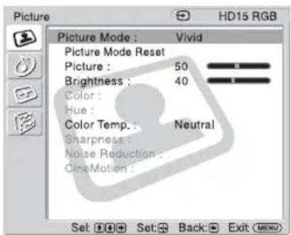
When input is switched to a PC input source, the "Picture" settings specific to PC input are applied. The PC "Picture" settings include the following options:
| Picture Mode | “Vivid”: Select for enhanced picture contrast and sharpness. “Standard”: Select for standard picture settings. “Custom”: Allows you to store preferred settings. |
| Picture Mode Reset | Reset all settings and adjustments currently selected in “Picture Mode” (“Vivid”, “Standard”, “Custom”) to the default setting (except for the options grayed out). |
| Picture | Adjust to increase or decrease picture contrast. |
| Brightness | Adjust to brighten or darken the picture. |
| Color Temp. | “Cool”: Select to give the white colors a blue tint. “Neutral”: Select to give the white colors a neutral tint. “Warm”: Select to give the white colors a red tint. |
Notes
- "Color", "Hue", "Sharpness", "Noise Reduction" and "CineMotion" are not available for PC input.
- If there is no signal currently being input, none of the options of the "Picture" setting can be selected.

Sound Settings
To highlight an option and to change settings, press

Press confirm the selection.
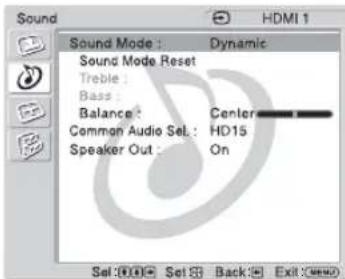
The "Sound" settings include the following options:
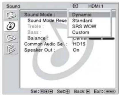
Sound Mode
"Dynamic": Select to enhance treble and bass.
"Standard": Flat setting.
"SRS WOW": Provides a panoramic stereo audio image by producing deep and rich bass tones and clear treble tones, enabling you to enjoy powerful sound effects like those in a movie theater.
"Custom": Allows you to store preferred settings.
Tips
- To change from one "Sound Mode" option to another, you can also use SOUND on the remote control instead.
- The proprietary technologies of BBE Sound, Inc. are applied for "Dynamic" and "Standard".
Sound Mode Reset
Reset the following settings; "Treble", "Bass" and "Balance" to the default settings.
Treble
Adjust to increase or decrease higher-pitched sounds.
Bass
Adjust to increase or decrease lower-pitched sounds.
Balance
Adjust to emphasize left or right speaker balance.
Common Audio Sel.
"HD15": Outputs audio from a piece of video equipment or PC connected to the HD15 (RGB/COMPONENT IN) connector and the AUDIO (COMMON AUDIO IN) connector.
"HDMI 1"/"HDMI 2": Select to connect a piece of equipment using an HDMI cable (not supplied) or an HDMI-to-DVI cable (not supplied), and the corresponding audio cable at the same time.
See page 8.
Notes
- When using an HDMI-to-DVI cable, connect the audio cable to the AUDIO (COMMON AUDIO IN) connector.
- When "HDMI 1"/"HDMI 2" is selected, digital audio is not output from the HDMI connectors. When a piece of video equipment equipped with an HDMI connector is connected to the HDMI 1/HDMI 2 connectors, set "Common Audio Sel." to "HD15". (The default setting is "HD15".)
Speaker Out
"On": Enables sound to be emitted from the display speaker.
"Off": Disables sound to be emitted from the display speaker.
Note
When "Speaker Out" is set to "Off", "Sound Mode", "Sound Mode Reset", "Treble", "Bass", and "Balance" cannot be selected.
Tip
You can adjust the "Sound" settings ("Treble" and "Bass") when the "Sound Mode" is set to "Custom".

Screen Settings
For Video Input
To highlight an option and to change settings, press

Press to confirm the selection.
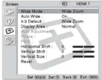
The "Screen" settings include the following options:
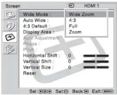
Wide Mode
"Wide Zoom": Select to enlarge to fill screen with minimum distortion.
"4:3": Select to display 4:3 picture in original size when the original source is 4:3 (Standard definition source).
"Full": Select to enlarge the original picture horizontally to fill the screen when the original source is 4:3 (Standard definition source). When the original source is 16:9 (High definition source), select this mode to display 16:9 picture in original size.
"Zoom": Select to enlarge the original picture without distorting the aspect ratio. See page 13.
Tips
- To change from one "Wide Mode" option to another, you can also use WIDE on the remote control instead.
- Select "Zoom" to display movies and other DVD content with black bands, using the entire viewable area of the screen.
- For "Wide Zoom" and "Zoom" modes, you can adjust "Horizontal Shift", "Vertical Shift", and "Vertical Size" of the picture. See page 22.
Note
"Wide Zoom" and "4:3" cannot be selected for 1080i, 720p, or 1080p signals input to the component or HDMI connectors.
Auto Wide
"On": Select to detect the image and change it automatically to the appropriate screen mode.
"Off": The screen mode does not change automatically.
Note
While inputting digital and analog RGB signals, you cannot set the "Auto Wide" because the "Auto Wide" function does not work.
| 4:3 Default | “Wide Zoom”: Select to enlarge the 4:3 picture to fill the 16:9 screen, keeping the original image as much as possible. “4:3”: Select to display the 4:3 picture without changing its aspect ratio. “Full”: Select to enlarge the 4:3 picture horizontally only, to fill the 16:9 screen. “Zoom”: Select to enlarge the 4:3 picture to fill the screen while keeping its aspect ratio. “Off”: Select to continue using the current “Wide Mode” setting when the input is changed. Tips • You can select “4:3 Default” only when “Auto Wide” is set to “On”. • “4:3 Default” functions only when the display receives NTSC, PAL, SECAM, 480i, 480p, 575i or 576p signals. • If “Wide Mode” setting is changed after “4:3 Default” is set, the “Wide Mode” setting will become effective and the aspect ratio of the screen will change. This setting change that was made afterward by “Wide Mode” will be effective only when each signal is input. Therefore, when the input signal is changed, the screen will return to the original “4:3 Default” setting. To keep the current aspect ratio even after the input signal is changed, set “4:3 Default” to “Off”. |
| Display Area | “Normal”: Displays a standard size picture. “-1”/“-2”: Allows you to adjust the viewable picture area size. When noises appear around the picture, select this to hide the noises. |
| Horizontal Shift | Allows you to move the position of the picture left and right in the window. Available only in “Wide Zoom” and “Zoom” modes. Press ↓/◆ and press ⊙ to choose a correction. |
| Vertical Shift | Allows you to move the position of the picture up and down in the window. Available only in “Wide Zoom” and “Zoom” modes. Press ↓/◆ and press ⊙ to choose a correction. |
| Vertical Size | Allows you to adjust the vertical size of the picture. Available only in “Wide Zoom” and “Zoom” modes. Press ↓/◆ and press ⊙ to choose a correction. |
| Reset | Reset the following settings; “Horizontal Shift”, “Vertical Shift” and “Vertical Size” to the default settings. |
Note
If there is no signal currently being input, none of the "Screen" settings options can be selected.
For PC Input
When input is switched to PC input source, the "Screen" settings specific for PC input are applied. The PC "Screen" settings include the following options:
| Wide Mode | “Normal”: Select to display the picture in its original size. “Full 1”: Select to enlarge the picture to fill the display area in the vertical direction while keeping its original aspect ratio. A black frame will appear on the surrounding of the picture. “Full 2”: Select to enlarge the picture to fill the display area. |
| Auto Adjustment | Select to automatically adjust the display position and phase of the picture when the display receives an input signal from the connected PC. Note that “Auto Adjustment” may not work well with certain input signals. In such cases, manually adjust the options below. |
| Phase | Select to adjust the phase when the screen flickers. |
| Pitch | Select to adjust the pitch when the picture has unwanted vertical stripes. |
| Horizontal Shift | Allows you to move the position of the picture left and right in the window. Press ⇌ and press to choose a correction. |
| Vertical Shift | Allows you to move the position of the picture up and down in the window. Press ⇌ and press to choose a correction. |
| Reset | Reset the following settings; “Phase”, “Pitch”, “Horizontal Shift” and “Vertical Shift” to the default settings. |
Notes
"Auto Wide", "4:3 Default", "Display Area" and "Vertical Size" are not available for PC input.
- When the input is digital signal via HDMI 1/HDMI 2, "Auto Adjustment", "Phase" and "Pitch" are not available for PC input.
- If there is no signal currently being input, none of the "Screen" settings options can be selected.

Setup Settings
To highlight an option and to change settings, press
↑/↓/←/→
Press to confirm the selection.
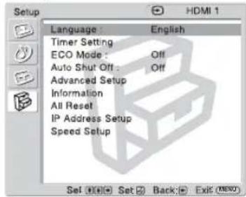
The "Setup" settings include the following options:
| Language | Select to display all on-screen settings in your language of choice: “English”,“Espanol”,“François”,“Italiano”,“Deutsch” or “日本語 |
| Timer Setting | You can adjust time, display the built-in clock, or make the power go off automatically.“Clock Set”: Sets the day of the week and the hour of the day.“Clock Display”: Displays the currently set time on the screen when set to “On”.“Sleep Timer”: Set the time in minutes (15 minutes, 30 minutes, 45 minutes, 60 minutes, 90 minutes, or 120 minutes) that you want the display to remain on before shutting off automatically.NoteIf the built-in clock tends to lose time, the internal battery may be exhausted. Please contact your authorized Sony dealer to have the battery replaced. |
| ECO Mode | “Off”: Select to view picture without the benefit of power saving.“Low”/“High”: Select to change brightness and reduce power consumption.“Picture Off”: Select to turn off the picture. Audio stays on with your selected volume setting. |
| Auto Shut Off | “On”: The display automatically enters the standby mode when a signal is not input to the video input connectors for more than about 5 minutes. The display automatically enters the power saving mode when a signal is not input to the other input connectors for more than about 30 seconds.“Off”: The display is not turned off automatically even when no signal is input to any connector.TipWhile in the standby mode, press the (POWER) button on the display or the POWER button on the remote control to turn the display on. In the power saving mode, the display is turned on automatically when a signal is input. |
| Advanced Setup | “Color System”: Select the “Color System” of video signals from “NTSC”, “PAL”, “SECAM”, “NTSC4.43”, “PAL-M”, “PAL-N”, “PAL60”, or select “Auto” to set the “Color System” automatically.“Status Display”: “On” makes input signal and “Wide Mode” information appear on the screen for about 20 seconds when the display is turned on, and for about 5 seconds when the input signal is switched, while “Off” disables display of status information.TipYou can display the input signal and “Wide Mode” information by using DISPLAY on the remote control regardless of the “Status Display” setting. |
| Information | Displays the “Model Name”, “Serial Number”, “Operation Time”, “Software Version” and “IP Address” of your display. |
| Note | |
| The “IP Address” is not shown if the optional adaptor with communication functions is not installed. | |
| All Reset | Reset all the “Setup” settings to the default settings. |
| Note | |
| The items included in the “Information” option will not be reset. | |
| IP Address Setup | Sets an IP address to enable the communication between the optional adaptor with communication functions, such as the BKM-FW32/FW50, installed in the display, and the equipment such as a PC connected with the LAN cable. “DHCP”: “OK” allows you to set an IP address automatically, and “Cancel” aborts automatic configuration. |
| Note | |
| When you obtain an IP address automatically using “DHCP”, an IP address may differ every time you turn the power of the display off and on. | |
| “Manual”: Select to set an IP address manually. | |
| 1 Select an “IP Address”, “Subnet Mask”, “Default Gateway”, “Primary DNS” “Secondary DNS” to be set manually with ↑/▼ and press ☑ | |
| 2 Set the three digit value (0 to 255) for the first box with ↑/▼ on the display or numeric keys on the remote control and press ☐ ▼. | |
| 3 Set the three digit value (0 to 255) for each of the four boxes and press . ☐ | |
| 4 Select the next item to be set manually with ↑/▼ and repeat the same procedure and press ☐ | |
| 5 After values are set for all the desired items, select “Execute” with ↑/▼, then press ☐ . Select “OK” and press An IP address is set manually. | |
| When an IP address is not set properly, the following error codes will be displayed in accordance with the error cause. | |
| Error 1: Communication error between the display and the optional adaptor such as the BKM-FW series | |
| Error 2: The specified IP address is already used for other equipment | |
| Error 3: IP address error | |
| Error 4: Gateway address error | |
| Error 5: Primary DNS address error | |
| Error 6: Secondary DNS address error | |
| Error 7: Subnet mask error | |
| Speed Setup | Sets a communication speed between the optional adaptor with communication functions, such as the BKM-FW32/FW50, installed in the display, and the equipment such as a PC connected with the LAN cable. “Speed”: Select “Auto” when you want to set an appropriate communication speed for your network configuration automatically. You can also select either of “10Mbps Half”, “10Mbps Full”, “100Mbps Half”, “100Mbps Full” manually. “Execute”: Select “OK” and press ☐ A communication speed has been set. |
Note
"IP Address Setup" and "Speed Setup" are not available if the optional adaptor with communication functions is not installed.
Displays the "Model Name", "Serial Number", "Operation Time", "Software Version" and "IP Address" of your display.
Note
The "TP Address" is not shown if the optional adaptor with communication functions is not installed.
Resets all the "Setup" settings to the default settings.
Note
The items included in the "Information" option will not be reset.
Other Information
Troubleshooting
Check whether the STANDBY indicator is flashing red.
When it is flashing
The self-diagnosis function is activated.
1 Check how many times the STANDBY indicator flashes and how long it stops flashing.
For example, the indicator flashes 3 times, stops flashing for 3 seconds, and flashes 3 times.
2 Switch the display off, and disconnect the power cord.
Inform your dealer or Sony service center of how the indicator flashes (the number of flashes and the duration of light out).
When it is not flashing
1 Check the items in the table below.
2 If the problem still persists, have your display serviced by qualified personnel.
Problem Possible Remedies
| No picture. | |
| No picture. | ·Check “ECO Mode” options (page 24). |
| The display turns off automatically. | ·Check if “Sleep Timer” is activated (page 24). |
| No picture from some video sources. | ·Check the connection between the video equipment and the display. ·Try switching input using the INPUT button of the display or the remote control (page 7, 11). |
| Poor picture. | |
| No color/Dark picture/The picture is too bright/Color is not correct | ·Press PICTURE to select the desired “Picture Mode” (page 11). ·Adjust the “Picture Mode” options in the “Picture” settings (page 18). ·Check the condition of the signal cable. |
| No sound/Noisy sound. | |
| Good picture, no sound. | ·Check the volume control. ·Press MUTING or VOL + on the remote control so that “Muting” disappears from the screen (page 11, 12). ·Check “Common Audio Sel.” settings (page 20). ·Check “Speaker Out” settings (page 20). |
| “Wide Mode” setting changes automatically. | ·The current “Wide Mode” setting automatically changes to the appropriate setting for the current input if “Auto Wide” in the “Screen” settings is set to “On”. If you want to retain the current “Wide Mode” setting as inputs are changed, set “Auto Wide” to “Off” in the “Screen” settings (page 21). |
| Remote control does not operate. | ·Check the polarity of the batteries or replace the batteries. ·Point the remote control at the remote control sensor of the display. ·Keep the remote control sensor area clear from obstacles. ·Check whether a cable is connected to the CONTROL S IN connector when using an optional adaptor with CONTROL S IN connector. The remote control cannot be used while the display is controlled via a CONTROL S connection. ·Fluorescent lamps can interfere with remote control operation; try turning off the fluorescent lamps. |
Input Signal Reference Chart
PC signals
| Resolution | horizontal frequency (kHz) | vertical frequency (Hz) | |
| 1 | \( VGA^{a)}-1(VGA 350)31.570 \) | ||
| 2 | 640 × 480@60 Hz (VESA b) STD) | 31.5 | 60 |
| 3 | Mac c) 13" 35.0 67 | ||
| 4 | VGA (VGA TEXT) 31.5 70 | ||
| 5 | 800 × 600@60 Hz (VESA STD) | 37.9 | 60 |
| 6 | Mac 16" 49.7 75 | ||
| 7 | 1024 × 768@60 Hz (VESA STD) | 48.4 | 60 |
| 8 | 1024 × 768@75 Hz (VESA STD) | 60.0 | 75 |
| 9 | 1024 × 768@85 Hz (VESA STD) | 68.7 | 85 |
| 10 | 1280 × 1024@60 Hz (VESA STD) | 64.0 | 60 |
| 11 | 848 × 480@60 Hz (VESA STD) | 29.8 | 60 |
| 12 | 848 × 480@60 Hz (VESA STD) | 29.5 | 60 |
| 13 | 848 × 480@75 Hz 37.7 75 | ||
| 14 | 1280 × 768@60 Hz 47.8 60 | ||
| 15 | 1280 × 768@60 Hz 47.4 60 | ||
| 16 | 1360 × 768@60 Hz 47.7 60 | ||
| 17 | 1360 × 768@60 Hz 47.4 60 |
TV/Video signals
a) VGA is a registered trademark of International Business Machines Corporation, U.S.A.
b) VESA is a registered trademark of the Video Electronics Standards Association.
c) Mac (Macintosh) is a registered trademark of Apple Computer, Inc.
Notes
- For HDTV signals, input the tri-level sync signal to the 2nd pin of RGB/COMPONENT (D-sub 15 pin) on the HD15 connector or the BKM-FW12 (optional adaptor).
- If colors appear too light after input of a DVD signal to the display, adjust "Color" in the "Picture" settings.
- When the phase is readjusted, the resolution will be reduced.
Actual on-screen display of the input signal and the display's status
| On-screen display | Significance |
| 640×480/60 (e.g.) | The selected input signal is a PC signal. |
| 480/60I (e.g.) | The selected input signal is component video. |
| NTSC (e.g.) | The selected input signal is NTSC. |
| Not Supported Signal | The selected input signal is non-supported signal. |
| No Signal There is no | input signal. |
| HD15 | The selected input signal is HD15. |
| HDMI 1 | The selected input signal is HDMI 1. |
| HDMI 2 | The selected input signal is HDMI 2. |
| Option | The selected input signal is OPTION. |
Specifications
Video processing
Panel system a-Si TFT Active Matrix LCD Panel
Display resolution 1,366 dots (horizontal) × 768 lines (vertical)
Sampling rate 13.5MHz to 140MHz
Color system NTSC, PAL, SECAM, NTSC4.43, PAL-M, PAL-N, PAL60
Input signal See page 27.
KLH-W26
Pixel pitch 0.421 (horizontal) × 0.421 (vertical) mm (^1 / 32×^1 / 32 inches)
Picture size 576 (horizontal) × 324 (vertical) mm (22^3 / 4× 12^7 / 8 inches)
Panel size 26-inch (diagonal 660~mm )
KLH-W32
Pixel pitch 0.510 (horizontal) × 0.510 (vertical) mm (^1 / 32×^1 / 32 inches)
Picture size 698 (horizontal) × 392 (vertical) mm (27^1 / 2× 15^1 / 2 inches)
Panel size 32-inch (diagonal 801mm )
Inputs and Outputs
HD15 (RGB/COMPONENT IN)
D-sub 15-pin (female) (× 1) (See page 29.)
AUDIO (COMMON AUDIO IN)
100 V to 240 V AC, 50/60 Hz,
KLH-W26:1.2 A
KLH-W32:1.3 A
Power consumption
KLH-W26:110W
KLH-W32:120W
Speaker output
10W + 10W (6 ohms)
Adequate load impedance, 6 to 16 ohms
Operating conditions
Temperature: 0^ to 35^
(32°F to 95°F)
Humidity: 20% to 90%
(no condensation)
Storing/transporting conditions
Temperature: -10^ to +40^
(14°F to 104°F)
Humidity: 20% to 90%
(no condensation)
Dimensions KLH-W26:
663× 505× 220mm
(26^1 / 8× 20× 8^3 / 4 inches)
KLH-W32:
798× 581× 220mm
(31^1 / 2× 22^7 / 8× 8^3 / _4 inches)
(w/h/d, excluding projections)
Mass KLH-W26: 13.5kg (29 lb 12 oz)
KLH-W32: 16.6kg (36 lb 10 oz)
Supplied accessories
AC power cord (1)
Remote Control RM-YA004 (1)
Size AA (R6) batteries (2)
Cable holder (1)
Operating instructions (1)
Optional accessories
Optional adaptors for system expansion, BKM-FW series
Safety regulations
UL 60950-1, CSA No. 60950-1-03 (c-UL),
FCC Class B, IC Class B,
EN 60950-1 (NEMKO), CE, C-Tick
Design and specifications are subject to change without notice.
Pin assignment
HD15 (RGB/COMPONENT) connector (D-sub 15-pin)
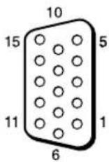
| Pin No. Signal | |
| 1 Red video or C | R/PR |
| 2 Green video or Y | |
| 3 Blue video or C | B/PB |
| 4 Ground | |
| 5 Ground | |
| 6 Red ground | |
| 7 Green ground | |
| 8 Blue ground | |
| 9 Not used | |
| 10 Ground | |
| 11 Ground | |
| 12 SDA | |
| 13 H sync or Composite Video | |
| 14 V sync | |
| 15 SCL |
Note
When inputting a component signal, be sure not to input sync signals to pins 13 and 14. If you do so, the picture may not be displayed properly.
Index
Numerics
4:3 13, 21
4:3 Default 22
A
ACINsocket10,15
Advanced Setup 24
All Reset 25
AUDIO (COMMON AUDIO IN)
connector 8
Auto Adjustment 23
Auto Shut Off 24
Auto Wide 21
B
Balance 20
Bass 20
Brightness 18, 19
C
Cable holder 15
CineMotion 18
Clock Display 24
Clock Set 24
Color 18
Color System 24
Color Temp. 18, 19
Common Audio Sel. 20
Custom 18, 19, 20
D
DHCP 25
Display Arca 22
DISPLAY button 11
Dynamic 20
E
ECOMode14,24
F
Full 13, 21
Full 1/Full 2 13, 23
H
HD15 (RGB/COMPONENT IN)
connector 8
HDMI 1/HDMI 2 IN connector 8
Horizontal Shift 22, 23
Hue 18
1
Information 25
INPUT button 7
INPUT V1-V5 buttons 11
Input signal 27
IP Address Setup 25
L
Language 24
M
Manual (IP Address Setup) 25
MENUButton7,12
MUTING button 12
N
Noise Reduction 18
Normal 13, 22, 23
0
OPTION slot 8, 9
P
Phase 23
PIC OFF/TIMER indicator 7
Picture 18, 19
PICTURE button 11
Picture Mode 18, 19
Picture Mode Reset 18, 19
Picture Settings 16, 18
Pitch 23
POWER button 7, 11
POWER indicator 7
POWERSAVINGbutton12,14
R
Remote control sensor 7
Reset 22, 23
RGB/COMPONENT ACTIVE
THROUGH Adaptor 9
s
Screen Settings 17, 21
Setup Settings 17, 24
Sharpness 18
SLEEP button 12, 14
Sleep Timer 14, 24
SOUND button 12
Sound Mode 20
Sound Mode Reset 20
Sound Settings 16, 20
Speaker Out 20
Speed Setup 25
SRS WOW 20
Stand attachment hole 10
Standard 18, 19, 20
STANDBY indicator 7
Status Display 24
T
Timer Setting 24
Treble 20
V
Vertical Shift 22, 23
Vertical Size 22
VIDEO INPUT Adaptor 9
Vivid 18, 19
VOL button 7, 11
W
WIDE button 11, 13
Wide Mode 13, 21, 23
WideZoom13,21
Z
Zoom 13, 21
AVENTISSEMENT
FCC Class B, IC Class B,
EN 60950-1 (NEMKO), CE, C-Tick
Manual (IP Address Setup) 25
Mode cinéma 13, 21, 23
Mode de l'imag 18, 19
Mode du son 20
Modc ECO 14, 24
N
Netteté 18
Normal 13, 22, 23
Nuance 18
P
Personnalise 18, 19, 20
Phase 23
Plein ecran 13, 21
Plein ecran 1/Plein ecran 2 13, 23
Pos. horizontale 22, 23
Pos. vertical 22, 23
Prise AC IN 10, 15
R
Réglages Image 16, 18
RGB/COMPONENT IN (D-Sub, 15-polig):
2RGB/COMPONENT OUT (D-Sub, 15-polig):
Abmcessungen KLH-W26:
663× 505× 220mm
KLH-W32:
798× 581× 220mm
KLH-W32: 16,6kg
INPUT V1-V5, Tasten 11
INPUT, Taste 7
IP Address Setup 25
K
Kabelhalter 15
Kontrast 18, 19
L
Lautspr.ausgang 20
M
Manual (IP Address Setup) 25
MENU,Taste7,12
MUTING, Taste 12
N
Normal 13, 22, 23
0
KLH-W32: 16,6kg
Manual (IP Address Setup) 25
Modo ancho 13, 21, 23
Modo ECO 14, 24
Modo imagen 18, 19
Modo sonido 20
N
Nitidez 18
Normal 13, 22, 23
0
Selec. audiocomings 20
Senal de entrada 28
FCC Class B, IC Class B,
EN 60950-1 (NEMKO), CE, C-Tick
Manual (IP Address Setup) 25
Menu Audio 16, 20
Riprist. Modo imm. 18, 19
Ripristina 22, 23
Ripristina toutto 25
S
(c-UL), FCC Class B, IC Class B,
EN 60950-1 (NEMKO), CE, C-Tick
设计和规格若要变更,恕不另行通知。
管脚配置
HD15 (RGB/COMPONENT) 连接器 (D-sub 15 芯)

Common Audio Sel. 20
Custom 18, 19, 20
D
DHCP 25
电缆夹15
Display Area 22
DISPLAY 键 11
Dynamic 20
E
ECO Mode 14, 24
F
Full 13.21
Full 1/Full 2 13, 23
H
Manual (IP Address Setup) 25
MENU 键 7,12
MUTING 键 12
N
Noise Reduction 18
Normal 13,22,23
0
OPTION插槽8,9
P
Phase 23
PIC OFF/TIMER指示灯7
Picture 18, 19
PICTURE 键 11
Picture Mode 18, 19
Picture Mode Reset 18, 19
Picture 设定 16, 18
Pitch 23
POWERSAVING键12,14
POWER键7,11
POWER指示灯7
R
Reset 22, 23
RGB/分量活动传递适配器9
S
Screen 设定 17, 21
Setup 设定17,24
Sharpness 18
Sleep Timer 14, 24
SLEEP键12,14
Sound Mode 20
Sound Mode Reset 20
SOUND键12
Sound 设定 16, 20
Speaker Out 20
Speed Setup 25
SRS WOW 20
Standard 18, 19, 20
STANDBY 指示灯7
Status Display 24
视频输入适配器9
输入信号27
T
Timer Setting 24
Treble 20
V
Vertical Shift 22, 23
Vertical Size 22
Vivid 18, 19
W
Wide Mode 13, 21, 23
WideZoom13,21
WIDE键11,13
Y
遥控传感器7
音量键7,11
Z
Zoom 13, 21
支架安装孔10


- Flat Wide Display Monitor
- 安全のたてに
- N
- To reduce the risk of fire or electric shock, do not expose this apparatus to rain or moisture.
- To avoid electrical shock, do not open the cabinet. Refer servicing to qualified personnel only.
- On transportation
- For customers in the U.S.A.
- Declaration of Conformity
- For customers in Canada
- CAUTION
- Trademark Information
- Table of Contents
- Introduction
- Location and Function of Parts and Controls
- Connections
- Using the Settings
- Other Information
- Precautions
- On safety
- On installation
- On the LCD panel
- On cleaning the display
- The panel surface
- The cabinet
- Notes on handling and cleaning the display panel
- On repacking
- For the State of California, USA only
- For Customers in the United States
- Recommendations on Installation
- Provide an ample amount of space around the display
- Front
- Front Panel
- MENU (page 16)
- 2/ + (INPUT)
- 3/ +
- 4/
- Note
- ⑥ PIC OFF/TIMER indicator
- 7STANDBYindicator
- POWER indicator
- 9R note control sensor
- Side Panel
- Optional Adaptors
- RGB/COMPONENT IN (D-sub 15-pin):
- RGB/COMPONENT OUT (D-sub 15-pin):
- Rear Panel
- Parts Description
- Remote Control
- Button Description
- POWER button
- DISPLAY button
- WIDE button
- 4PICTURE button
- INPUT V1-V5 buttons
- 6VOL + / - button
- Tip
- MENU button
- / / / / buttons
- SLEEP button
- 10FREEZE button
- POWERSAVINGbutton
- SOUND button
- 3MUTING button
- Special Buttons on the Remote Control
- Using the Wide Mode
- 4:3 Original Source
- 16:9 Original Source
- For PC Input
- Using the Sleep Function
- To cancel Sleep Timer
- Notes
- Using the ECO Mode Function
- To cancel the ECO Mode
- Before you start
- Connecting the AC Power Cord and Arranging the Input Cables
- Overview of the Menus
- To change the on-screen language
- Settings Allows you to set/change
- Picture
- Sound
- Screen
- Setup
- Picture Settings
- For Video Input
- Picture Mode
- Tips
- Picture Mode Reset
- Brightness
- Color
- Hue
- Color Temp.
- Sharpness
- Noise Reduction
- CineMotion
- Sound Settings
- Sound Mode
- Sound Mode Reset
- Treble
- Bass
- Balance
- Common Audio Sel.
- Speaker Out
- Screen Settings
- Wide Mode
- Auto Wide
- Setup Settings
- Troubleshooting
- Check whether the STANDBY indicator is flashing red.
- When it is flashing
- When it is not flashing
- Input Signal Reference Chart
- Actual on-screen display of the input signal and the display's status
- Specifications
- Video processing
- KLH-W26
- KLH-W32
- Inputs and Outputs
- HD15 (RGB/COMPONENT IN)
- AUDIO (COMMON AUDIO IN)
- Pin assignment
- Index
- Numerics
- A
- B
- C
- D
- E
- F
- H
- 1
- L
- M
- 0
- P
- R
- s
- T
- V
- W
- Z
- AVENTISSEMENT
- K
- 管脚配置
- Y
Brand : SONY
Model : KLHW26
Category : Television