S1032 - Surveillance Camera AXIS - Free user manual and instructions
Find the device manual for free S1032 AXIS in PDF.
User questions about S1032 AXIS
0 question about this device. Answer the ones you know or ask your own.
Ask a new question about this device
Download the instructions for your Surveillance Camera in PDF format for free! Find your manual S1032 - AXIS and take your electronic device back in hand. On this page are published all the documents necessary for the use of your device. S1032 by AXIS.
USER MANUAL S1032 AXIS
AXIS Camera Station S1032 Recorder
AXIS Camera Station S1048 Recorder
About this Document
This document includes instructions for installing AXIS Camera Station S1032 Recorder and AXIS Camera Station S1048 Recorder on your network. Previous experience of networking will be beneficial when installing the product.
Legal Considerations
Video and audio surveillance can be regulated by laws that vary from country to country. Check the laws in your local region before using this product for surveillance purposes.
Liability
Every care has been taken in the preparation of this document. Please inform your local Axis office of any inaccuracies or omissions. Axis Communications AB cannot be held responsible for any technical or typographical errors and reserves the right to make changes to the product and manuals without prior notice. Axis Communications AB makes no warranty of any kind with regard to the material contained within this document, including, but not limited to, the implied warranties of merchantability and fitness for a particular purpose. Axis Communications AB shall not be liable nor responsible for incidental or consequential damages in connection with the furnishing, performance or use of this material. This product is only to be used for its intended purpose.
Intellectual Property Rights
Axis AB has intellectual property rights relating to technology embodied in the product described in this document. In particular, and without limitation, these intellectual property rights may include one or more of the patents listed at www.axis.com/patent.htm and one or more additional patents or pending patent applications in the US and other countries.
Equipment Modifications
This equipment must be installed and used in strict accordance with the instructions given in the user documentation. This equipment contains no user-serviceable components. Unauthorized equipment changes or modifications will invalidate all applicable regulatory certifications and approvals.
Trademark Acknowledgments
Dell™ is a trademark of Dell Inc. Ethernet, Internet Explorer, WWW are registered trademarks of the respective holders. Microsoft®, Windows®, MS-DOS®, Windows Vista®, the Windows Vista start button, and Office Outlook® are either trademarks or registered trademarks of Microsoft Corporation in the United States and/or other countries. Java and all Java-based trademarks and logos are trademarks or registered trademarks of Oracle and/or its affiliates.
Contact Information
Axis Communications AB
Emdalavägen 14
223 69 Lund
Sweden
Tel: +46 46 272 18 00
Fax: +46 46 13 61 30
www.axis.com
Support
Should you require any technical assistance, please contact your Axis reseller. If your questions cannot be answered immediately, your reseller will forward your queries through the appropriate channels to ensure a rapid response. If you are connected to the Internet, you can:
- download user documentation and firmware updates
- find answers to resolved problems in the FAQ database. Search by product, category, or phrases
• report problems to Axis support by logging in to your private support area
- chat with Axis support staff (selected countries only)
- visit Axis support at www.axis.com/techsup
Copyright
©2014 Axis Communications AB, © 2013 Dell Inc. All rights reserved. This product is protected by U.S. and international copyright and intellectual property laws. AXIS COMMUNICATIONS, AXIS, ETRAX, ARTPEC and VAPIX are registered trademarks or trademark applications of Axis AB in various jurisdictions. All other company names and products are trademarks or registered trademarks of their respective companies. We reserve the right to introduce modifications without notice.
AXIS S1032/AXIS S1048 Installation Guide
This installation guide provides instructions for installing AXIS Camera Station S1032 Recorder and AXIS Camera Station S1048 Recorder. For more information about how to use the product, go to www.axis.com
Installation Steps
- Hardware overview. See page 4.
-
Connect the cables:
-
AXIS S1032. See page 6.
-
AXIS S1048. See page 8.
-
Set up software. See page 10.
- Network configuration. See page 10.
- Get Started. See page 10.
Package Contents
- AXIS Camera Station S1032 Recorder or AXIS Camera Station S1048 Recorder
- Power cables
- Rails mount kit
- Bezel and bezel key
- C a b l e s t r a p s
• Safety Regulation document
• Installation Guide (this document)
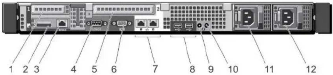
Hardware Overview - AXIS S1032
Back Panel
text_image
1 2 3 4 5 6 7 8 9 10 11 12| 1 PCIe expansion card slot 1 7 Ethernet connectors (2) |
| 2 vFlash media card slot (Optional) 8 USB connectors (2) |
| 3 iDRAC port (Optional) 9 System identification connector |
| 4 Serial connector 10 System identification button |
| 5 PCIe expansion card slot 2 11 Power supply (PSU1) |
| 6 Video connector 12 Power supply (PSU2) |
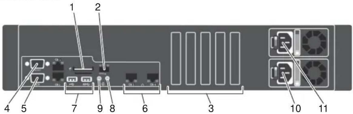
Hardware Overview - AXIS S1048
Back Panel
text_image
1 2 4 5 7 9 8 6 3 10 11| 1 vFlash media card slot (Optional) 7 USB connectors (2) |
| 2 iDRAC port (Optional) 8 System identification connector |
| 3 PCIe expansion card slots (5) 9 System identification button |
| 4 Serial connector 10 Power supply (PSU2) |
| 5 Video connector 11 Power supply (PSU1) |
| 6 Ethernet connectors (2) |
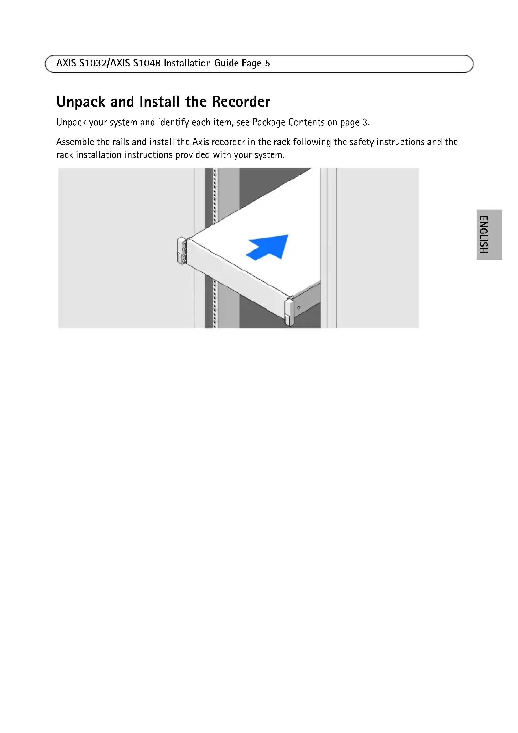
Unpack and Install the Recorder
Unpack your system and identify each item, see Package Contents on page 3.
Assemble the rails and install the Axis recorder in the rack following the safety instructions and the rack installation instructions provided with your system.

natural_image
3D illustration of a white shelf with a blue arrow pointing upward, mounted on a metal frame (no text or symbols)Connect the Cables - AXIS S1032
Warning: Before you begin any of the procedures in this section, read the safety information that shipped with your computer. For additional information, see www.axis.com
NOTE: Some devices may not be included if you did not order them.
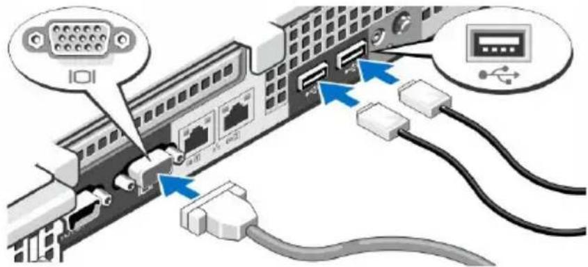
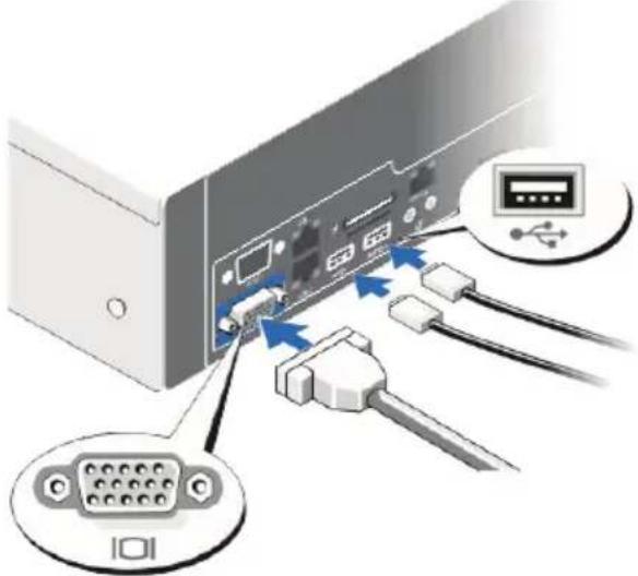
- Connect the keyboard, mouse and monitor. The connectors on the back of your system have icons indicating which cable to plug into each connector. Be sure to tighten the screws (if any) on the monitor's cable connector.
text_image
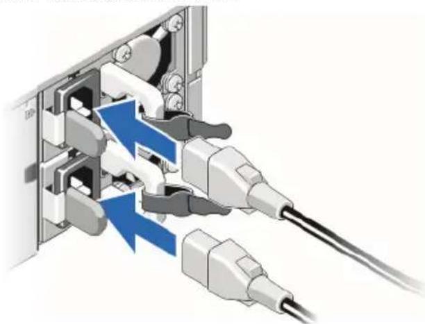
Diagram showing network connection between a USB drive and server, with labeled ports and connectors- Connect the system's power cable(s) to the system and, if a monitor is used, connect the monitor's power cable to the monitor.
natural_image
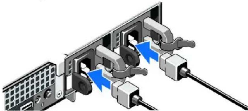
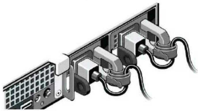
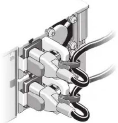
Diagram of a computer interface showing cable connections and internal components (no text or symbols)- Secure the power cables by bending the system power cables, as shown in the illustration, and attach to the cable straps. Plug the other end of the power cables into a grounded electrical outlet or a separate power source such as an uninterruptible power supply (UPS) or a power distribution unit (PDU).
natural_image
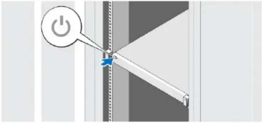
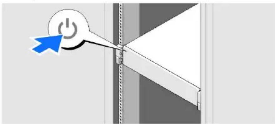
Diagram of a computer interface with multiple connected ports and cables (no text or symbols visible)- Press the power button to turn on the recorder. The power indicator should light up.
text_image
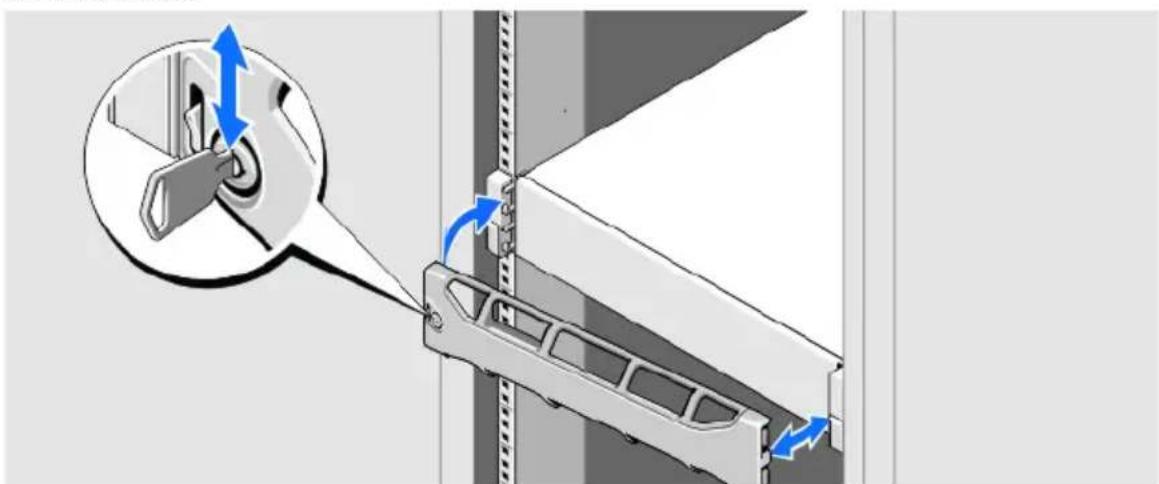
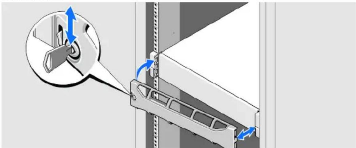
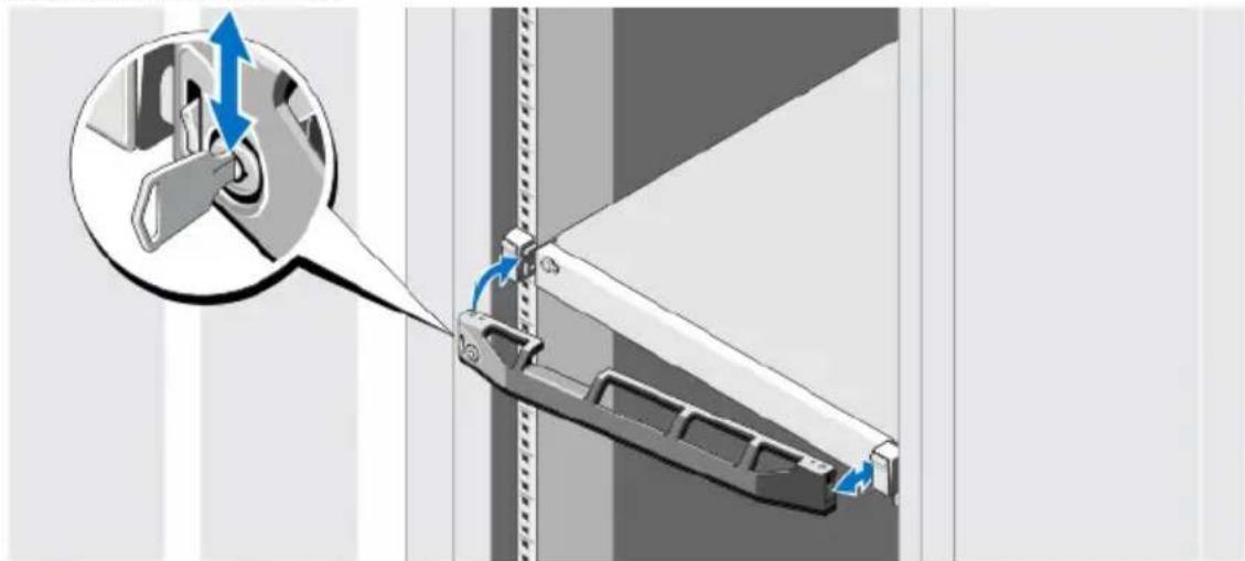
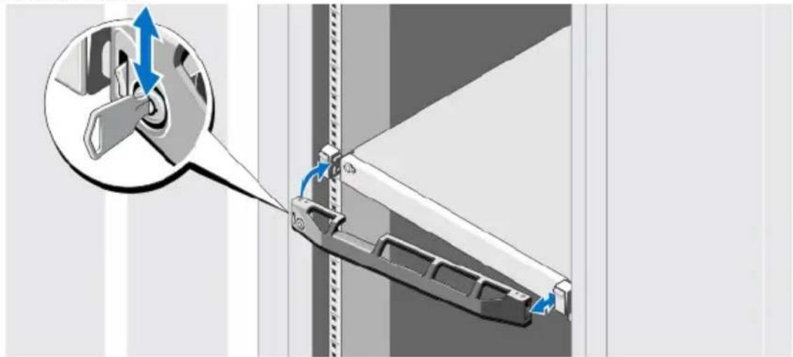
Diagram showing a power button icon pointing to a vertical line segment with a blue arrow, likely illustrating a switch or thresholding process.- Install the bezel.

natural_image
Mechanical assembly diagram showing a lever mechanism with blue directional arrows indicating motion (no text or symbols present)Connect the Cables - AXIS S1048
Warning: Before you begin any of the procedures in this section, read the safety information that shipped with your computer. For additional information, see www.axis.com
NOTE: Some devices may not be included if you did not order them.
- Connect the keyboard, mouse and monitor. The connectors on the back of your system have icons indicating which cable to plug into each connector. Be sure to tighten the screws (if any) on the monitor's cable connector.
text_image
Diagram showing connection between a computer interface with labeled components including USB port, VGA, and USB cable.- Connect the system's power cable(s) to the system and, if a monitor is used, connect the monitor's power cable to the monitor.
natural_image
Diagram of a cable connector with blue lightning bolt indicating internal connection (no text or symbols)- Secure the power cables by bending the system power cables, as shown in the illustration, and attach to the cable straps. Plug the other end of the power cables into a grounded electrical outlet or a separate power source such as an uninterruptible power supply (UPS) or a power distribution unit (PDU).
natural_image
Mechanical assembly diagram showing bundled cables and components (no text or symbols)- Press the power button to turn on the recorder. The power indicator should light.
natural_image
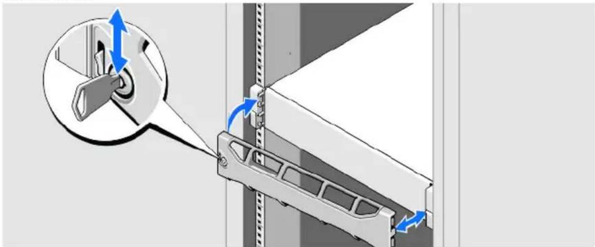
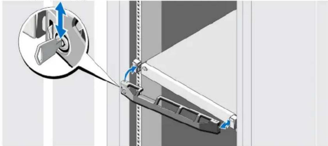
Diagram showing a power button icon pointing to a vertical barrier, with no visible text or symbols.- Install the bezel.
natural_image
Technical diagram showing a mechanical assembly with blue directional arrows indicating motion or force, no text or symbols present.iDRAC Express
This product includes the Integrated Dell Remote Access Controller (iDRAC) Express. iDRAC Express can be used to manage, update and deploy servers in large installations. iDRAC allows you to remotely monitor the health of this product in order to discover problems, such as failing hard drives as soon as possible and to avoid system downtime. For more information, go to www.dell.com
Set Up Software
When the recorder has been powered on, the Windows operating system will be installed. Follow the instructions displayed on the screen and provide the required information. When the Windows installation is finalized, double-click on the AXIS Camera Station Client shortcut on the Windows desktop to start AXIS Camera Station.
Network Configuration
AXIS Camera Station can record and play back video from cameras and video encoders that are connected to a LAN (Local Area Network) or to a WAN (Wide Area Network). Depending on the installation, follow the instructions under Network & Security Configuration in AXIS Camera Station User Manual available at www.axis.com
Get Started
AXIS Camera Station Client and the wizard "Get Started with AXIS Camera Station" start automatically when the installation is complete. "Get Started with AXIS Camera Station" provides a quick way to add cameras and to configure and enable recording:
- Select cameras and video encoders to add.
- Select recording methods and where to store recordings.
- Review settings and click Finish to add cameras and start recording.
For more information, see the built-in help and AXIS Camera Station User Manual available at www.axis.com
AXIS Camera Station S9001 Desktop Terminal
It is recommended to use AXIS S1032/S1048 together with AXIS Camera Station S9001 Desktop Terminal. AXIS S9001 is a desktop terminal with a preinstalled AXIS Camera Station Client. Use AXIS S9001 to access live and recorded video and to manage cameras and recordings. The desktop terminal's graphics card is optimized for viewing live and recorded video from multiple cameras.
First install the AXIS S1032/S1048 recorder. Then install AXIS S9001 and start AXIS Camera Station Client. From AXIS S9001, log in to the AXIS Camera Station Server installed in the AXIS S1032/S1048 recorder.
It is not recommended to use AXIS S1032/S1048 for accessing video. The preinstalled AXIS Camera Station Client is intended for initial configuration and not for active use.
Specifications AXIS S1032/AXIS S1048
Note:
The following specifications are only those required by law to ship with your system. For a complete and current listing of the specifications for your system, go to www.axis.com/support
Power:
AC Power Supply (per power supply)
| AXIS S1032 AXIS S1048 | ||
| Wattage 350 W 495 W | ||
| Heat dissipation 1356 BTU/hr maximum | maximum 1908 BTU/hr maximum | |
| VoltageNote:This system is also designed to be connected to IT power systems with a phase to phase voltage not exceeding 230 V | 100–240 V AC, autoranging, 50/60 Hz | 100–240 VAC, autoranging, 50/60 Hz |
| BatteryCoin-cell battery | 3 V CR2032 Lithium coin cell 3 | V CR2032 Lithium coin cell |
Note:
Heat dissipation is calculated by using the power supply wattage rating.
Physical:
| AXIS S1032 AXIS S1048 | ||
| Height 42.8 mm (1.68 inch) 86.8 mm (3.41 inch) | ||
| Width With rack latches 482.4 mm(18.99 inch)Without rack latches 434.0 mm (17.09 inch) | With rack latches 482.4 mm (18.99 inch)Without rack latches 434.0 mm (17.09 inch) | |
| Depth (excludes bezel) 607.0 mm (23.9 inch) 646 mm (25.4 inch) | ||
| Weight 13.6 kg (30.0 lb) 18.9 kg (41.7 lb) | ||
Environmental:
Temperature
| AXIS S1032 AXIS S1048 | ||
| Operating Continuous operation | 10 °Cto 35 °C at 10% to 80%relative humidity (RH), with 26 °C max dew point. De-rate maximum allowable dry bulb temperature at 1 °C/300 m above 900 m (1°F per 550 ft).Note:For information on supported expanded operating temperature range and configurations, see support.dell.com/manuals. | Continuous operation: 10 °C to 35 °C at 10% to 80% relative humidity (RH), with 29 °C max dew point. De-rate maximum allowable dry bulb temperature at 1 °C/300 m above 950 m (1°F per 550 ft).Note:For information on supported expanded operating temperature range and configurations, see support.dell.com/manuals. |
| Storage -40 °C to 65 °C (-40 °F) | to 149°F) with a maximum temperature gradation of 20 °C per hour | -40 °C to 65 °C (-40 °F to 149 °F) with a maximum temperature gradation of 20 °C per hour |
Relative humidity
| AXIS S1032 AXIS S1048 | ||
| Operating 10% to 80% (noncondensing) 10% to 80% (noncondensing) | ||
| Storage 5% to 95% (noncondensing) 5% to 95% (noncondensing) | ||
Further information
For more information about the product visit www.axis.com
Visit Axis learning center www.axis.com/academy for useful trainings, webinars, tutorials and guides.
Warranty
For information about Axis' product warranty and thereto related information, see www.axis.com/warranty
AXIS S1032/AXIS S1048 Guide d'installation
text_image
Diagram of a server rack with labeled ports and connectors, showing internal components like drive, ports, and fan units.natural_image
3D illustration of a white shelf with a blue arrow pointing upward, mounted on a metal frame (no text or symbols)text_image
Diagram showing network connection between a server and USB drive, with labeled ports and cable connectionsnatural_image
Diagram of a server rack with connected ports and cable, showing blue directional arrows indicating internal connections (no text or symbols present)natural_image
Diagram of a computer interface with multiple ports and cables (no text or symbols visible)text_image
Diagram showing a power button icon pointing to a switch, with a blue star marking the switch's tip.- Installez le cache.

natural_image
Mechanical assembly diagram showing a lever mechanism with blue directional arrows indicating motion (no text or symbols present)text_image
Diagram showing connection between a computer interface with labeled components including USB port, VGA, and USB cable connections.natural_image
Diagram of a cable connector with blue arrows indicating internal components (no text or symbols)natural_image
Mechanical assembly diagram showing bundled cables and components (no text or symbols)natural_image
Diagram showing a power button icon pointing to a vertical barrier, with no text or symbols present.- Installez le cache.
natural_image
Mechanical assembly diagram showing a component being inserted into a wall, with blue arrows indicating direction of motion (no text or symbols present)iDRAC Express
AXIS Camera Station S9001 Desktop Terminal
AXIS S1032/AXIS S1048
natural_image
3D illustration of a white shelf with a blue arrow pointing upward, mounted on a metal frame (no text or symbols)text_image
Diagram showing network connection between a server and USB drive, with labeled ports and connectorsnatural_image
Diagram of a server rack with connected ports and cable, showing blue directional arrows indicating internal connections (no text or symbols present)natural_image
Diagram of a computer interface with multiple ports and cables (no text or symbols visible)text_image
Diagram showing a power button icon connected to a vertical line with a star symbol, likely illustrating a switch or thresholding process.natural_image
Mechanical assembly diagram showing a lever mechanism with blue directional arrows indicating motion (no text or symbols present)text_image
Diagram showing connection between a computer interface with labeled components including USB port, VGA, and USB cable.natural_image
Diagram of a cable connector with blue lightning bolt indicating internal connection (no text or symbols)natural_image
Mechanical assembly diagram showing bundled cables and components (no text or symbols)natural_image
Diagram showing a power button icon pointing to a vertical barrier, with no visible text or symbols.natural_image
Mechanical assembly diagram showing a component being inserted into a housing with blue directional arrows indicating motion (no text or symbols present)iDRAC Express
AXIS Camera Station S9001 Desktop Terminal
natural_image
Diagram showing a blue arrow pointing upward on a white rectangular panel mounted on a wall, with no text or symbols present.Collegare i cavi: AXIS S1032
text_image
Diagram showing network connection between a server and Ethernet ports with labeled connectors and port iconsnatural_image
Diagram of a server rack with two connected ports and blue directional arrows indicating internal connections (no text or symbols present)natural_image
Diagram of a computer interface with multiple ports and cables (no text or symbols visible)text_image
Diagram showing a power button icon connected to a switch, with a blue star marking the switch's position.- Installare la mascherina.
natural_image
Mechanical assembly diagram showing a lever mechanism with blue directional arrows indicating motion (no text or symbols present)Collegare i cavi: AXIS S1048
text_image
Diagram showing connection between a computer interface with labeled components including USB port, VGA, and USB cable.natural_image
Diagram of a cable connector with blue arrows indicating internal components (no text or symbols)natural_image
Diagram of electrical cable connections inside a device (no text or symbols visible)natural_image
Diagram showing a power button icon pointing to a vertical barrier, with no text or symbols present.- Installare la mascherina.

natural_image
Mechanical assembly diagram showing a bracket with blue directional arrows indicating motion or force (no text or symbols present)iDRAC Express
AXIS Camera Station S9001 Desktop Terminal
natural_image
3D illustration of a white shelf with a blue arrow pointing upward, mounted on a metal frame (no text or symbols)text_image
Diagram showing network connection between a server and Ethernet ports with labeled connectors and port iconsnatural_image
Diagram of a computer interface showing cable connections and internal components (no text or symbols)natural_image
Diagram of a computer interface with multiple ports and cables (no text or symbols visible)text_image
Diagram showing a power button icon pointing to a blue star at a junction, likely illustrating a switch or control mechanism.- Instale el bisel.
natural_image
Mechanical assembly diagram showing a lever mechanism with blue directional arrows indicating motion (no text or symbols present)text_image
Diagram showing connection between a computer interface with labeled components including USB port, VGA, and USB cable.natural_image
Diagram of a cable connector with multiple connectors and cables, showing internal wiring and blue directional arrows (no text or symbols)natural_image
Mechanical assembly diagram showing coiled cable and housing components (no text or symbols)natural_image
Diagram showing a power button icon pointing to a vertical barrier, with no visible text or symbols.- Instale el bisel.
natural_image
Diagram of a mechanical assembly with blue directional arrows indicating motion or force, showing internal components and alignment (no text or symbols)iDRAC Express
AXIS S1032/AXIS S1048
インストールガイド
natural_image
Diagram showing a blue arrow pointing upward on a white rectangular panel mounted on a wall, with no text or symbols present.text_image
Diagram showing network connection between a server with I/O port, USB drive, and USB cable via USB portnatural_image
Diagram of a server rack with two connected ports and blue directional arrows indicating internal connections (no text or symbols present)natural_image
Diagram of a computer interface with multiple connected ports and cables (no text or symbols visible)text_image
Diagram showing a power button icon pointing to a vertical line segment with a blue arrow, likely illustrating a switch or lever mechanism.- ベゼルを取り付けます。
natural_image
Mechanical assembly diagram showing a lever mechanism with blue directional arrows indicating motion (no text or symbols present)natural_image
Diagram showing connections between a computer interface with ports, cables, and a USB port (no text or symbols present)natural_image
Diagram of a cable installation with two connected plugs and a blue arrow indicating direction (no text or symbols)natural_image
Mechanical assembly diagram showing connections between components (no text or symbols visible)natural_image
Diagram showing a cursor clicking a power button on a wall, with no visible text or symbols- ベゼルを取り付けます。

natural_image
Diagram of a mechanical assembly with directional arrows indicating motion or force, showing a component being inserted into a housing (no text or symbols present)iDRAC Express
AXIS Camera Station S1032 Recorder, AXIS Camera Station S1048 Recorder
© 2015 Axis Communications AB
© 2013 Dell Inc.
Ver.2.0
Printed: March 2015
Part No. 62700