ACE15 - Speaker FENDER - Free user manual and instructions
Find the device manual for free ACE15 FENDER in PDF.
| Product type | Speaker (two-way passive) |
| Brand | Fender |
| Model | ACE-15 |
| Frequency response | 65 Hz – 18 kHz |
| Input impedance | 8 Ω nominal |
| Power handling (program) | 600 W |
| Power handling (peak) | 1,200 W |
| Max SPL (1 m) | 120 dB |
| Sensitivity (1 W/1 m) | 98 dB |
| Woofer | 15" (381 mm) with 3" (76.2 mm) aluminum voice coil |
| Tweeter | Compression, 44 mm titanium diaphragm, rotatable horn 90° x 60° |
| Dimensions (H x Front W x Rear W x D) | 700 x 485 x 140 x 460 mm |
| Weight | 26 kg |
| Enclosure material | Injection-molded polypropylene (high temperature, impact-resistant, waterproof, UV-resistant) |
| Connectors | 6.35 mm jack and Speakon NL4 (4-pin) in parallel |
| Pole mount | Aluminum 1 3/8" (35 mm) |
| Handles | 2 integrated handles |
| Protective grille | High-strength steel |
| Recommended use | Live sound, DJ, concerts, stage monitors |
| Safety | Floor/wall mounting required, do not expose to rain or moisture |
| Maintenance and cleaning | Clean with a dry cloth, do not use liquids |
| Repairability | No user-serviceable parts, consult a qualified professional |
Frequently Asked Questions - ACE15 FENDER
User questions about ACE15 FENDER
0 question about this device. Answer the ones you know or ask your own.
Ask a new question about this device
Download the instructions for your Speaker in PDF format for free! Find your manual ACE15 - FENDER and take your electronic device back in hand. On this page are published all the documents necessary for the use of your device. ACE15 by FENDER.
USER MANUAL ACE15 FENDER
This symbol warns the user of dangerous voltage levels localized within the enclosure.

This symbol advises the user to read all accompanying literature for safe operation of the unit.
Δ Read, retain, and follow all instructions. Heed all warnings.
△ WARNING: To prevent injury, this apparatus must be securely attached to the floor/wall in accordance with the installation instructions.
Δ WARNING: Flying loudspeakers above crowds is dangerous and should only be undertaken by experienced and insured riggers.
△ WARNING: The length of the useful life of these cabinets will depend in substantial part upon how they are treated in use. The user of this cabinet must periodically have this cabinet inspected to ensure that continued use has not weakened the cabinet's structure, including the various joints which are fastened with glue and/or screws.
△ WARNING: To prevent damage, fire or shock hazard, do not expose this unit to rain or moisture.
Δ This product should be located away from heat sources such as radiators, heat registers, or other products that produce heat.
Δ This product should only be used with a cart or stand that is recommended by the manufacturer.
Δ This product should be serviced by qualified service personnel when: objects have fallen, or liquid has been spilled onto the product; or the product has been exposed to rain; or the product does not appear to operate normally or exhibits a marked change in performance; or the product has been dropped, or the enclosure damaged.
Δ Do not drip nor splash liquids, nor place liquid filled containers on the unit.
△ CAUTION: No user serviceable parts inside, refer servicing to qualified personnel only.
Δ Fender ^® loudspeaker systems are capable of producing very high sound pressure levels which may cause temporary or permanent hearing damage. Use care when setting and adjusting volume levels during use.
General Precautions:
Δ Always carefully route speaker cables to avoid any chance that someone could trip over them. Tripping over the cables attached to the speaker can cause the speaker to be knocked over, potentially leading to personal injury and damaged equipment.
Δ Due to the high acoustical energy generated by the speakers, they may have a tendency to move across smooth, polished, or slippery surfaces. Care should be taken to ensure the speakers do not fall off of the edge of such surfaces (i.e. stages, tables, etc.).
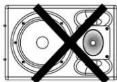
Δ Do not insert or drop anything into the ACE Speaker enclosure's bass ports (located on either side of the high frequency horn).
When stacking ACE loudspeakers:
Do not stack more than two units high.
Δ Stacked speakers must be securely strapped or tied together and anchored to the stage to prevent toppling.
Δ Always ensure that the loudspeakers are placed on a stable surface. The surface must be rigid, flat, and level.
Δ Always verify that stacked speakers are aligned properly. The feet of the upper speaker must fully interlock with the receptacles of the lower speaker.
Δ Position the loudspeakers in a location where they will not be easily tipped over by audience members, performers, or the production crew.
Δ Do not allow anyone to lean on or climb on speakers.
Δ Children should not be allowed near stacked speakers.
Δ When used outdoors, be aware of winds that could tip a speaker stack over.
When mounting ACE loudspeakers on speaker stands:
Δ Always ensure that the stand is placed on a stable surface. The surface should be rigid, flat, and level.
Δ The legs of tripod style speaker stands must be fully extended, and the stand should be positioned so that its legs do not pose a trip hazard.
Δ Read and observe all safety precautions provided by the stand manufacturer.
Δ Check the specifications of the speaker stand to verify its weight limits. Ensure that it is designed to support the weight of the speaker. Never mount more speakers on a stand designed for only a single speaker.
Δ In outdoor applications, additional precautions should be taken to ensure stability. Sandbags placed on the base of the stand may improve stability.

- Well damped injection molded speaker enclosure made from an advanced polymer
- Built-in handle(s)
- Two-way passive crossover with high-frequency driver protection
- Asymmetrical rotatable horn for adjustable coverage pattern
- Compression drivers with 1 3/4" titanium diaphragms and annular phase plug
- Cast aluminum pole mount
- Extremely rugged high-power woofer
- 3" Voice coil with massive 18 AWG copper-clad aluminum ribbon wire
• High efficiency design
• Heavy duty protective steel grill - Two input connectors:
- 4-pole Neutrik® Speakon® NL4 connector
• 1/4" Phone Jack
INTRODUCTION
Thank you for purchasing an ACE ^™ Series Loudspeaker system from Fender ^® Pro Audio. We are sure you will find it both a unique and effective sound reinforcement product, providing years of trouble-free service. The ACE ^™ Series Loudspeakers are professional, full-range, two-way, compact loudspeakers designed for the most demanding concert sound and live performance requirements.
The ACE ^™ Series Loudspeakers feature passive two-way crossovers with a high-frequency driver protection circuit. The protection circuitry allows ACE ^™ Loudspeakers to handle occasional power spikes that would destroy most other speaker systems.
ACE ^™ Loudspeakers have horns that can be rotated, allowing adjustment of the coverage area. This feature allows the user optimize the sound dispersion depending on the application and orientation of the speakers.
The compression drivers in the ACE ^™ Series Loudspeakers have 1 3/4" titanium diaphragms and annular phase plugs for superior frequency response. The woofers are designed for maximum efficiency and robust power handling.
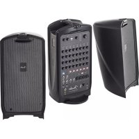
The well-damped speaker enclosures are made from an advanced polymer using an injection molding process. With up to two built-in handles and cast aluminum pole mounts, ACE ^™ Loudspeakers are perfect for bands and DJ's that are on the go. ACE ^™ Loudspeakers are designed to form the basis of anything from a P.A. system for a band to a full-size concert sound tour system. They can be used as a single unit, in pairs, or as part of a larger loudspeaker array. These speakers are ideal for use as a two-way system or as the mid / high pack in a three-way set-up incorporating a subwoofer loudspeaker system.
CAUTION: Almost all speakers produce strong magnetic fields which may interfere with the normal operation of nearby electronic devices, including televisions and computer video monitors. To reduce or eliminate interference, increase the distance between this product and other nearby electronic devices.
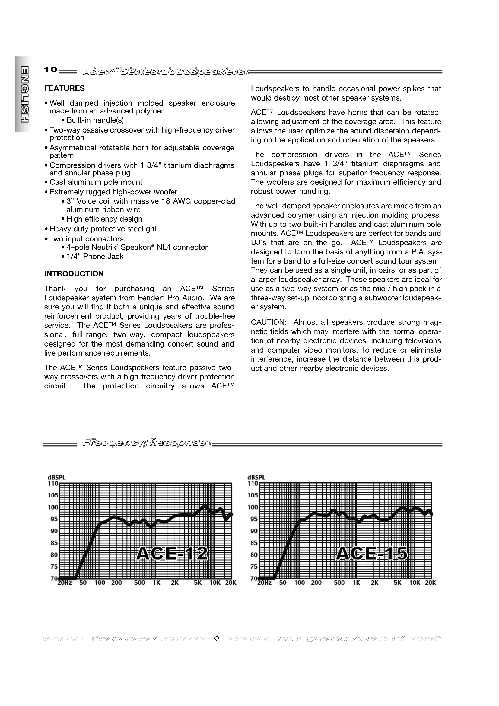
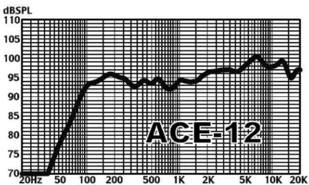
FrequencyResponse
line
| Frequency | dB SPL | | --------- | ------ | | 20Hz | 70 | | 50 | 85 | | 100 | 95 | | 200 | 96 | | 500 | 94 | | 1K | 93 | | 2K | 95 | | 5K | 98 | | 10K | 97 | | 20K | 96 |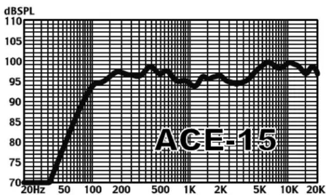
line
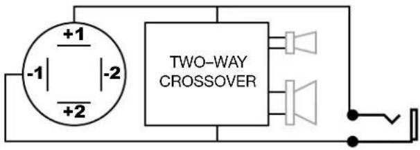
| Frequency | dB SPL | | --------- | ------ | | 20Hz | 70 | | 50 | 85 | | 100 | 95 | | 200 | 98 | | 500 | 97 | | 1K | 95 | | 2K | 96 | | 5K | 98 | | 10K | 99 | | 20K | 97 |The ACE™ Series Loudspeakers have both a 1/4" phone jack and a 4-pole Neutrik® Speakon® (NL4) style input connections. The connectors are wired as follows:
Polarity 1/4"Phone Jack NL4 Speakon®
| Positive (+) Tip | 1+ |
| Negative (−) Sleeve | 1- |
The 1/4" jack and the NL4 Speakon® connector are wired in parallel. This allows either connector to be used as an input and the other as an output. Never use both as inputs!
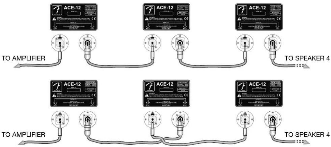
Multiple loudspeakers can be daisy chained (linked), eliminating the need for several long cumbersome runs of speaker cable. There are two ways to daisy chain several ACE™ speakers together. One way is to use cables with a 1/4" phone plug on one end and a 4-pole Neutrik® Speakon® plug on the other end. The second way is to use cables with 1/4" phone plugs on both ends and cables with Speakon® plugs on both ends, alternating from one speaker to the next (see illustration).
Each additional loudspeaker in a daisy chain configuration will reduce the total impedance load. Make sure that you stay above the minimum impedance load rating for your amplifier to avoid damage to your equipment. Below are the total impedance loads of ACE™ series loudspeakers linked:
| Number of Cabinets: | 2 | 3 | 4 |
| Total Impedance Load: | 4Ω | 2.6Ω | 2Ω |
Prevent power loss and the degradation of sound quality by using heavier (lower gauge number) speaker cables when:
- Long speaker cables are necessary
- Two or more loudspeakers are linked together
With ONE loudspeaker, connections up to:
•25-feet require 18-gauge cable
- 50-feet require 16-gauge cable
•100-feet require 14-gauge cable
With TWO loudspeakers, linked, connections up to:
•25-feet require 16-gauge cable
- 50-feet require 14-gauge cable
•100-feet require 12-gauge cable
With THREE loudspeakers, linked, connections up to:
•25-feet require 14-gauge cable
- 50-feet require 12-gauge cable
•100-feet require 10-gauge cable
With FOUR loudspeakers, linked, connections up to:
•25-feet require 12-gauge cable
- 50-feet require 10-gauge cable
•100-feet require 8-gauge cable
flowchart
graph TD
    A["ACE-12 Module"] --> B["TO AMPLIFIER"]
    C["ACE-12 Module"] --> D["TO AMPLIFIER"]
    E["ACE-12 Module"] --> F["TO AMPLIFIER"]
    G["ACE-12 Module"] --> H["TO AMPLIFIER"]
    I["ACE-12 Module"] --> J["TO AMPLIFIER"]
    K["ACE-12 Module"] --> L["TO AMPLIFIER"]
    M["ACE-12 Module"] --> N["TO AMPLIFIER"]
    O["ACE-12 Module"] --> P["TO AMPLIFIER"]
    Q["ACE-12 Module"] --> R["TO AMPLIFIER"]
    S["ACE-12 Module"] --> T["TO AMPLIFIER"]
    U["ACE-12 Module"] --> V["TO AMPLIFIER"]
    W["ACE-12 Module"] --> X["TO AMPLIFIER"]
    Y["ACE-12 Module"] --> Z["TO AMPLIFIER"]
    AA["ACE-12 Module"] --> AB["TO AMPLIFIER"]
    AC["ACE-12 Module"] --> AD["TO AMPLIFIER"]
    AE["ACE-12 Module"] --> AF["TO AMPLIFIER"]
    AG["ACE-12 Module"] --> AH["TO AMPLIFIER"]
    AI["ACE-12 Module"] --> AJ["TO AMPLIFIER"]
    AK["ACE-12 Module"] --> AL["TO AMPLIFIER"]
    AM["ACE-12 Module"] --> AN["TO AMPLIFIER"]
    AO["ACE-12 Module"] --> AP["TO AMPLIFIER"]
    AQ["ACE-12 Module"] --> AR["TO AMPLIFIER"]
    AS["ACE-12 Module"] --> AT["TO AMPLIFIER"]
    AU["ACE-12 Module"] --> AV["TO AMPLIFIER"]
    AW["ACE-12 Module"] --> AX["TO AMPLIFIER"]
    AY["ACE-12 Module"] --> AZ["TO AMPLIFIER"]
    BA["ACE-12 Module"] --> BB["TO AMPLIFIER"]
    BC["ACE-12 Module"] --> BD["TO AMPLIFIER"]
    BE["ACE-12 Module"] --> BF["TO AMPLIFIER"]
    BG["ACE-12 Module"] --> BH["TO AMPLIFIER"]
    BI["ACE-12 Module"] --> BJ["TO AMPLIFIER"]
    BK["ACE-12 Module"] --> BL["TO AMPLIFIER"]
    BM["ACE-12 Module"] --> BN["TO AMPLIFIER"]
    BO["ACE-12 Module"] --> BP["TO AMPLIFIER"]
    BQ["ACE-12 Module"] --> BR["TO AMPLIFIER"]
    BS["ACE-12 Module"] --> BT["TO AMPLIFIER"]
    BU["ACE-12 Module"] --> BV["TO AMPLIFIER"]
    BW["ACE-12 Module"] --> BX["TO AMPLIFIER"]
    BY["ACE-12 Module"] --> BZ["TO AMPLIFIER"]
    CA["ACE-12 Module"] --> CB["TO AMPLIFIER"]
    CC["ACE-12 Module"] --> CD["TO AMPLIFIER"]
    CE["ACE-12 Module"] --> CF["TO AMPLIFIER"]
    DG["ACE-12 Module"] --> DH["TO AMPLIFIER"]
    DI["ACE-12 Module"] --> DJ["TO AMPLIFIER"]
    DK["ACE-12 Module"] --> DL["TO AMPLIFIER"]
The placement of any speaker can dramatically affect its sound. Thus, there are several considerations to review when placing loudspeakers. For best coverage, the speakers should be placed or mounted above head level. This allows the high-frequencies to reach members of the audience located in the back. The larger the audience, the higher the speakers should be placed.
The horn in your ACE ^™ Series speakers can be oriented for “wide” or “tall” coverage.
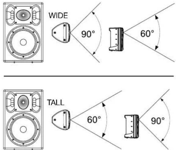
Consider speaker placement and coverage needs to determine the best horn position. In the “wide” position, horizontal coverage is 90^ and vertical coverage is 60^ . In the “tall” position, vertical coverage is 90^ and horizontal coverage is 60^ .
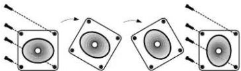
natural_image
Diagram showing three stages of speaker arrangement with arrows indicating direction (no text or symbols)To rotate the horn, first remove the four corner screws. Pull the horn out just enough to rotate it, taking care not to disconnect the wires. Replace the four corner screws.
Other considerations are feedback and bass performance. If the speaker is placed near a large, flat wall, bass output will be increased by approximately 6 dB. However, placing the speaker near a wall can cause feedback. If this occurs, the speaker must be moved. In general, placing speakers near a wall works best if the sources feeding the speaker are line level items. To reduce microphone feedback, use cardioid pattern microphones, keeping them behind, and pointed away from loudspeakers.
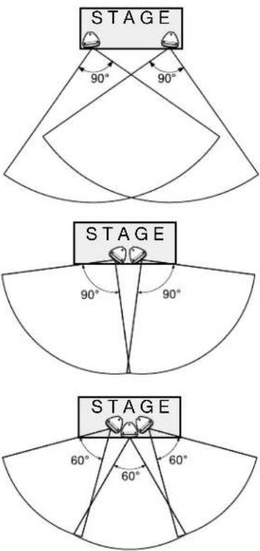
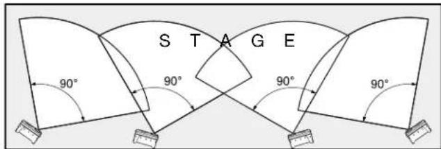
When loudspeakers are used in stereo, (either singly or in clusters), they should be separated and angled so that the coverage patterns overlap.
When loudspeakers are clustered, they should be angled so that the coverage patterns do not overlap. Speakers groups of two should have their horns oriented in the "wide" position.
Loudspeaker groups of three should have their horns oriented in the "tall" position. For larger venues, loudspeaker clusters can be treated as single units.
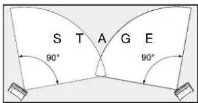
Your ACE ^TM loudspeakers can also be used as stage monitors when placed on their sides.
When used as a stage monitor, the horn should be rotated to the "wide" position relative to the floor to provide uniform coverage.
Larger stages may require additional monitors.
MODEL: ACE-15 ACE-12
| PART NUMBER: | 071-5015-000 | 071-5012-000 | |
| FREQUENCY RESPONSE: | 65Hz - 18kHz | 70Hz - 18kHz | |
| INPUT IMPEDANCE: | 8Ω Nominal | 8Ω Nominal | |
| POWER OUTPUT | EIA RS-426B: | 300 W | 300 W |
| PROGRAM: | 600 W | 600 W | |
| PEAK: | 1200 W | 1200 W | |
| SPL | MAXIMUM SPL @ 1M: | 120 dB | 119 dB |
| SENSITIVITY (1W & 1M): | 98 dB | 97 dB | |
| WOOFER | DRIVER SIZE: | 15 in (381 mm) | 12 in (305 mm) |
| VOICE COIL SIZE: | 3 in (76.2 mm) | 3 in (76.2 mm) | |
| VOICE COIL CONDUCTOR: | 0.75mm^2 Copper Clad Aluminum Ribbon | 0.75mm^2 Copper Clad Aluminum Ribbon | |
| COMPRESSION DRIVER | DIAPHRAGM SIZE: | 1 3/4 in (44.0 mm) | 1 3/4 in (44.0 mm) |
| DIAPHRAGM MATERIAL: | Titanium | Titanium | |
| EXIT THROAT: | 1 in (25.4 mm) | 1 in (25.4 mm) | |
| HORN | DISPERSION (H X V): | 90° x 60° | 90° x 60° |
| ROTATABLE: | Yes | Yes | |
| DIMENSIONS | WEIGHT: | 57.3 lb (26.0 kg) | 39.7 lbs (18.0 kg) |
| HEIGHT: | 27.6 in (700 mm) | 24.4 in. (620 mm) | |
| WIDTH (FRONT): | 19.1 in (485 mm) | 16.3 in. (415 mm) | |
| WIDTH (REAR): | 5.5 in (140 mm) | 4.7 in. (120 mm) | |
| DEPTH: | 18.1 in (460 mm) | 15.0 in. (382 mm) | |
| CABINET | MATERIAL: | Injection Molded Polypropylene | Injection Molded Polypropylene |
| FEATURES: | High Temp Anti-shock Water Resistant UV Resistant Well Damped 2 built in handles | High Temp Anti-shock Water Resistant UV Resistant Well Damped 1 built in handle | |
| POLE MOUNT: | 1 3/8 in (34.9 mm) Cast Aluminum | 1 3/8 in (34.9 mm) Cast Aluminum | |
| CONNECTORS: | 1/4 in Phone Jack NL4 Speakon® (4-pole) | 1/4 in Phone Jack NL4 Speakon® (4-pole) | |
CE
Product specifications are subject to change without notice.
CARACTERISTICAS
natural_image
Diagram showing four speaker components with arrows indicating motion (no text or symbols)natural_image
Diagram showing four stages of speaker arrangement with arrows indicating motion (no text or symbols)natural_image
Diagram showing four stages of speaker arrangement with arrows indicating motion (no text or symbols)natural_image
Diagram showing four stages of speaker arrangement with arrows indicating direction (no text or symbols)natural_image
Diagram showing four stages of speaker or speaker conversion with arrows indicating direction (no text or symbols)ACE^TM is a trademark and Fender^® is a registered trademark of FMIC.
Other trademarks are properties of their respective owners.
Copyright © 2004 FMIC P/N 063202
REV A