
X12000 - Projector BENQ - Free user manual and instructions
Find the device manual for free X12000 BENQ in PDF.
| Brand | BenQ |
| Model | X12000 |
| Product Type | DLP 4K UHD Projector |
| Native Resolution | 3840 x 2160 (4K UHD) |
| Brightness | 2200 ANSI lumens |
| Contrast | 50,000:1 |
| Light Source | UHP Lamp |
| Lamp Life | Up to 3000 hours (normal mode) |
| Power Supply | 100-240 V AC, 50/60 Hz |
| Power Consumption | 450 W (max) |
| Dimensions (projector) | 470 x 224 x 564 mm (W x H x D) |
| Weight (projector) | 15.0 kg |
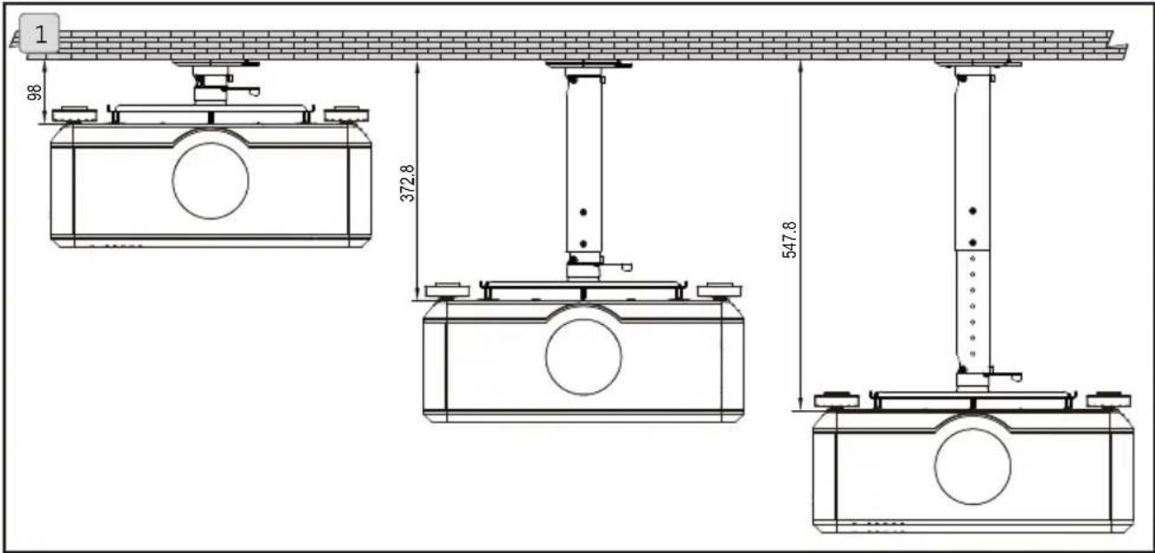
| Mounting Bracket Dimensions | Adjustable length from 98 to 547.8 mm |
| Mounting Bracket Weight | 3.39 kg |
| Bracket Load Capacity | Up to 30 kg |
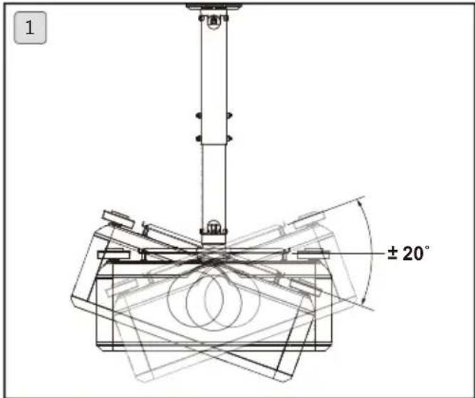
| Tilt Angle | ±20° |
| Rotation Angle | 360° |
| Bracket Material | Steel / Aluminum alloy |
| Key Features | 4K projection, HDR compatibility, keystone correction, 1.5x optical zoom |
| Maintenance and Cleaning | Clean lens with a soft cloth; replace air filter every 500 hours |
| Safety | Professional installation required; do not install in humid or dusty area; use a support suitable for the weight |
| Spare Parts and Repairability | Replacement lamp (model: 5J.J8H05.001), air filter, ceiling mount kit |
| General Information | Manufacturer warranty: 2 years; mounting bracket warranty: 5 years |
Frequently Asked Questions - X12000 BENQ
User questions about X12000 BENQ
0 question about this device. Answer the ones you know or ask your own.
Ask a new question about this device
Download the instructions for your Projector in PDF format for free! Find your manual X12000 - BENQ and take your electronic device back in hand. On this page are published all the documents necessary for the use of your device. X12000 by BENQ.
USER MANUAL X12000 BENQ
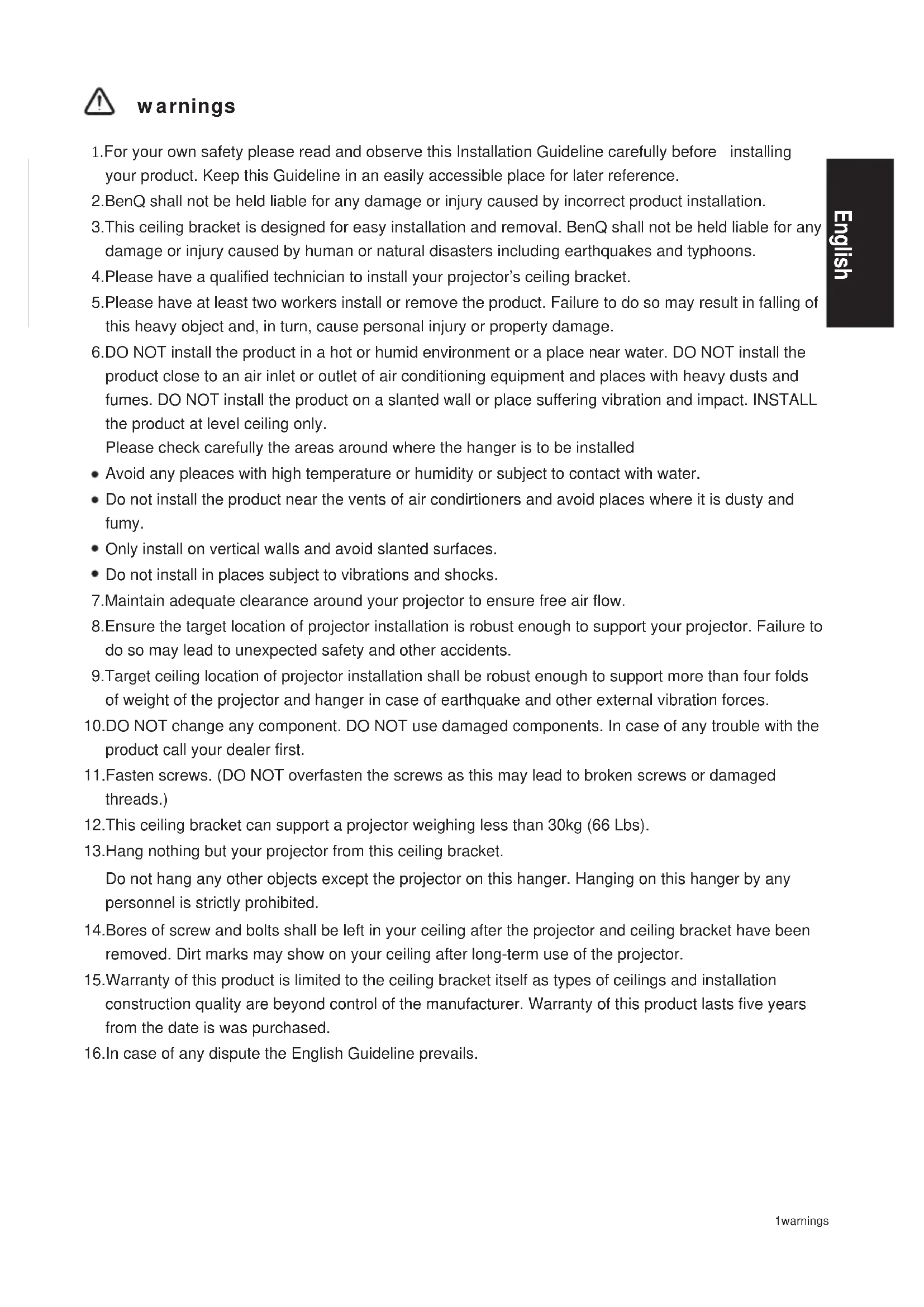
- For your own safety please read and observe this Installation Guideline carefully before installing your product. Keep this Guideline in an easily accessible place for later reference.
- BenQ shall not be held liable for any damage or injury caused by incorrect product installation.
- This ceiling bracket is designed for easy installation and removal. BenQ shall not be held liable for any damage or injury caused by human or natural disasters including earthquakes and typhoons.
- Please have a qualified technician to install your projector's ceiling bracket.
- Please have at least two workers install or remove the product. Failure to do so may result in falling of this heavy object and, in turn, cause personal injury or property damage.
- DO NOT install the product in a hot or humid environment or a place near water. DO NOT install the product close to an air inlet or outlet of air conditioning equipment and places with heavy dusts and fumes. DO NOT install the product on a slanted wall or place suffering vibration and impact. INSTALL the product at level ceiling only.
Please check carefully the areas around where the hanger is to be installed
- Avoid any pleaces with high temperature or humidity or subject to contact with water.
- Do not install the product near the vents of air conditioners and avoid places where it is dusty and fumy.
- Only install on vertical walls and avoid slanted surfaces.
-
Do not install in places subject to vibrations and shocks.
-
Maintain adequate clearance around your projector to ensure free air flow.
-
Ensure the target location of projector installation is robust enough to support your projector. Failure to do so may lead to unexpected safety and other accidents.
-
Target ceiling location of projector installation shall be robust enough to support more than four folds of weight of the projector and hanger in case of earthquake and other external vibration forces.
-
DO NOT change any component. DO NOT use damaged components. In case of any trouble with the product call your dealer first.
-
Fasten screws. (DO NOT overfasten the screws as this may lead to broken screws or damaged threads.)
-
This ceiling bracket can support a projector weighing less than 30kg (66 Lbs).
13.Hang nothing but your projector from this ceiling bracket.
Do not hang any other objects except the projector on this hanger. Hanging on this hanger by any personnel is strictly prohibited.
-
Bores of screw and bolts shall be left in your ceiling after the projector and ceiling bracket have been removed. Dirt marks may show on your ceiling after long-term use of the projector.
-
Warranty of this product is limited to the ceiling bracket itself as types of ceilings and installation construction quality are beyond control of the manufacturer. Warranty of this product lasts five years from the date is was purchased.
-
In case of any dispute the English Guideline prevails.
Specifications
| Substance | Steel/aluminum alloy |
| Weight | 3.39 kg (7.47 lbs) |
| Length | 98mm, 372.8mm~547.8mm(in unit of 25mm) |
| Rotation angle | 360° |
| Tilt angle | +/-20° |
| Load | 30kg (66 lbs) |
| Screws | M4,M6 |
Length
- Variable length in range of 98mm\~547.8mm (in unit of 25mm).
Adjustment angle
- Tilt angle in range of -20^ +20^ .
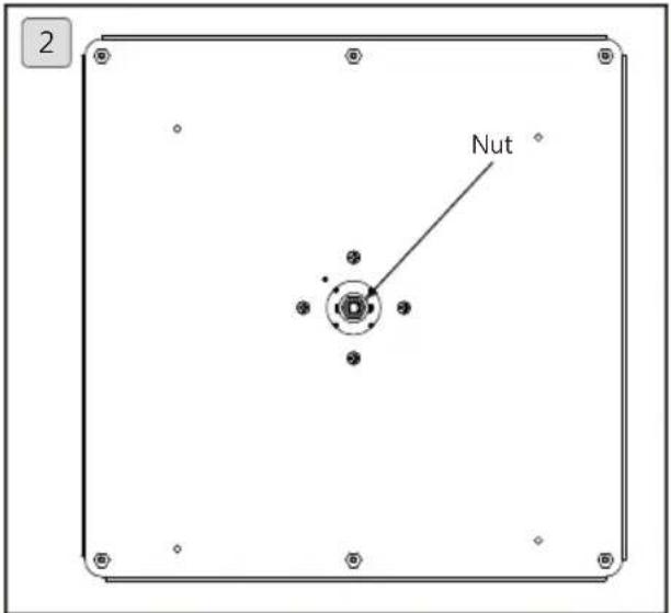
- The nut is designed to adjust slackness of projector angle.

Have qualified technician to adjust the nuts.
Accessory pack
| A B C D Ceiling bracket x 1 Projector holder x 1 | -2 | Hexagon stud (M4xL12) x 4 | Bolt x 2 | |||
| E (M6xL12) x 7 | F G H Hexagon wrench (5mm) x 1Hexagon screw with washer (M6xL10) x 4 | Screw with washer (M6xL10) x 4 | Nut x 2 | |||
| I Expansion stud x 4 | J Tapping screw x 4 | K Outer tube x 1 Inner tube x 1 | L Outer tube x 1 Inner tube x 1 | |||
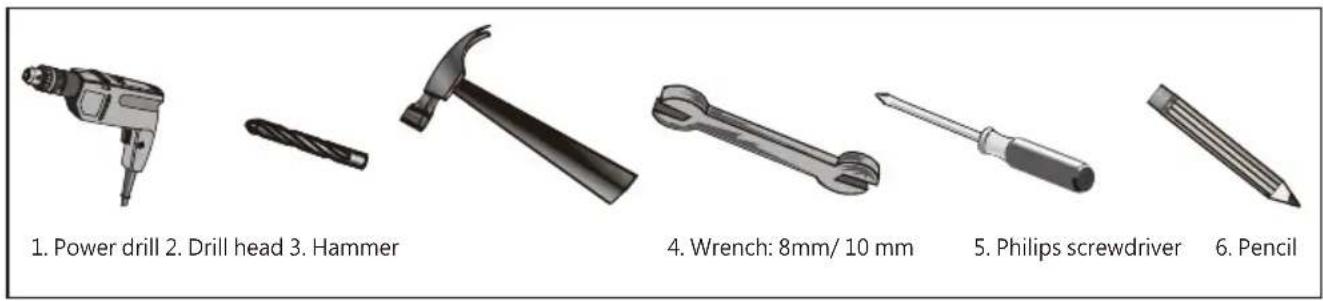
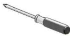
Tools needed for installation
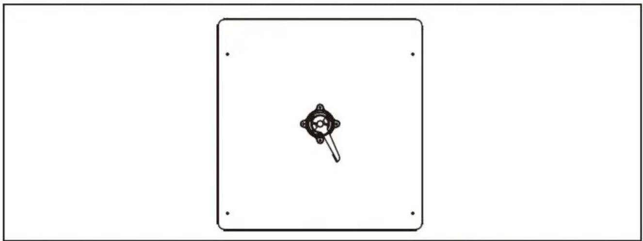
Bore location
Please visit site www.benq.com
natural_image
Simple line drawing of a device with a central knob and mounting holes, enclosed in a rectangular frame (no text or symbols)Installation steps
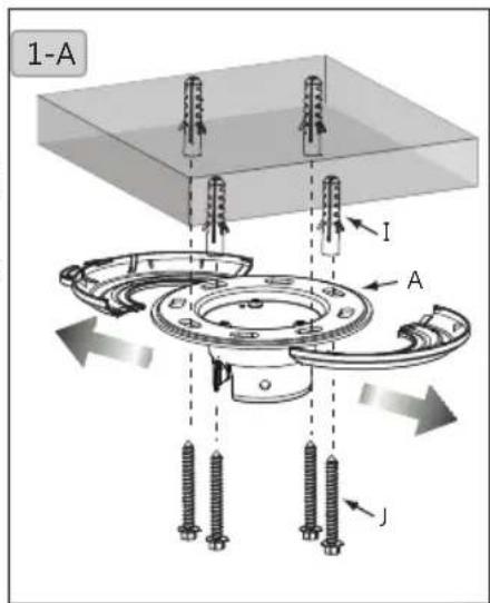
1. Install the hanger to your ceiling
1-A. Pull open the plastic cover to the right and left. Place the ceiling bracket (A) close to target location to your ceiling. Mark the bracket hole with pencil. Drill holes at marked location of diameter x depth of 10mm (0.39") x 55mm (2.17") for concrete and 4.5mm (0.17") x 55mm (2.17") for wood ceilings. Hammer the plastic expansion stud (I) in the hole and tapping screw (J) in the stud then cover the hole with plastic cap.
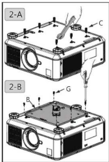
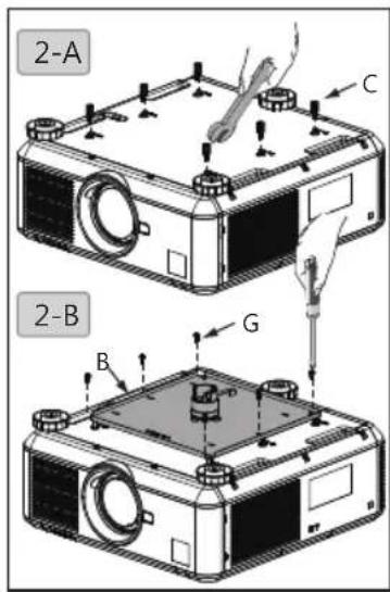
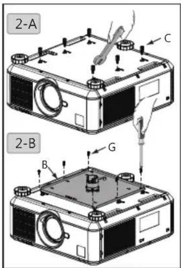
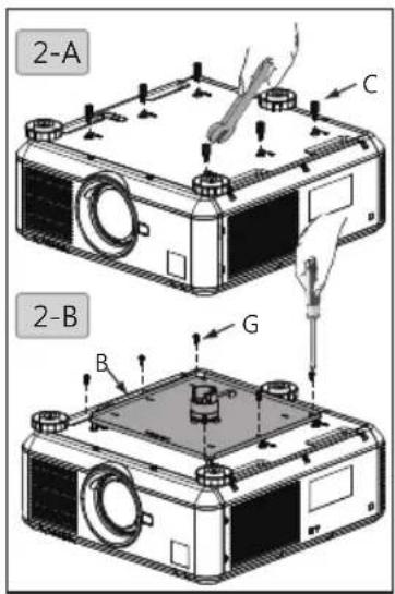
2. Install projector holder to the projector
2-A. Fasten hexagon stud (M4xL12) (C) to your projector with 8mm wrench.
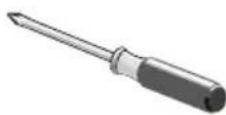
2-B. Fasten projector holder (B) to your projector by locking the screws with washer (G) with Philip screwdriver.
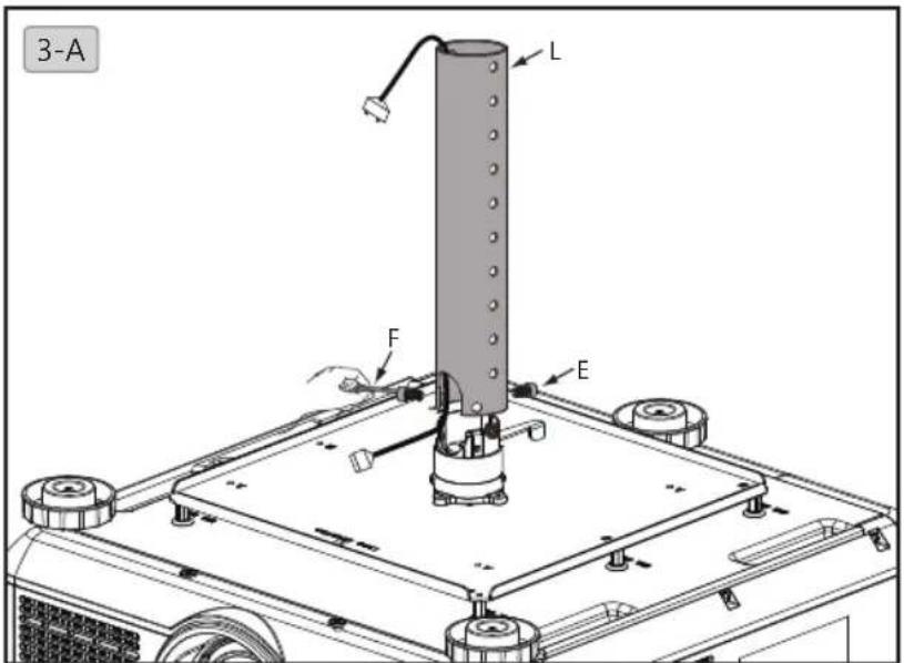
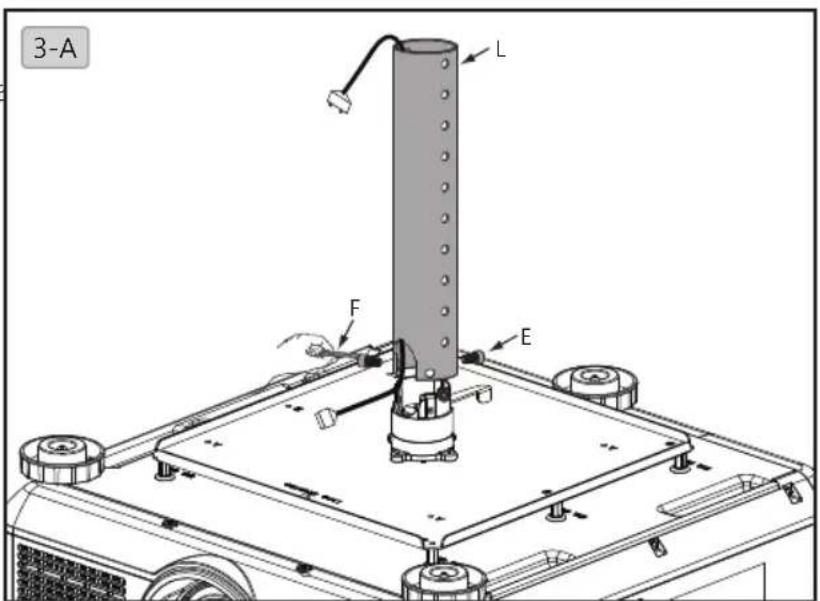
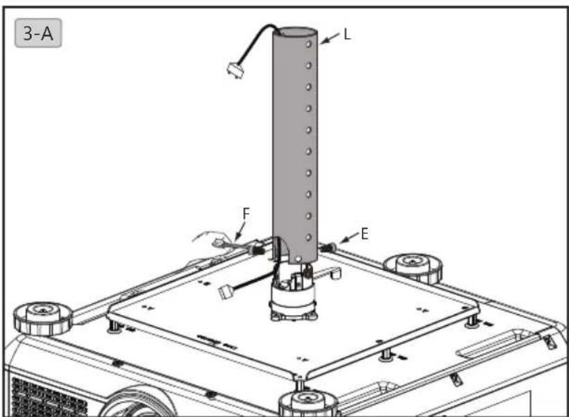
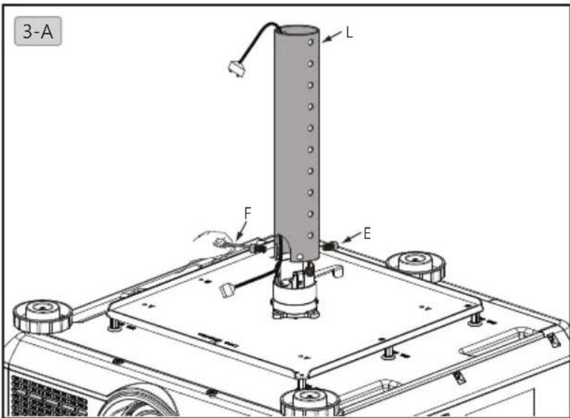
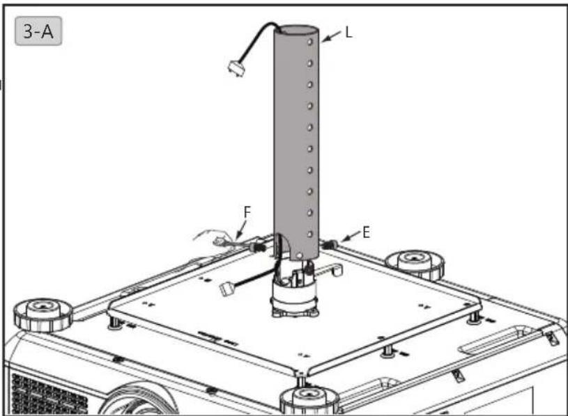
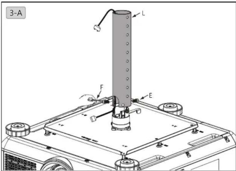
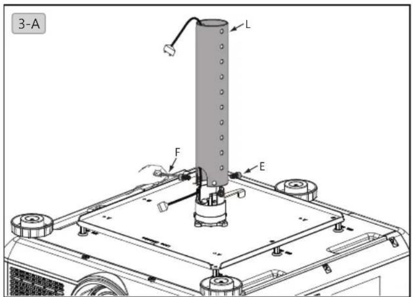
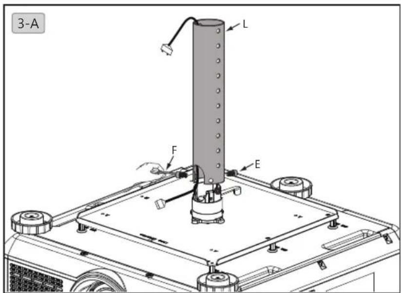
3. Select length of projector holder
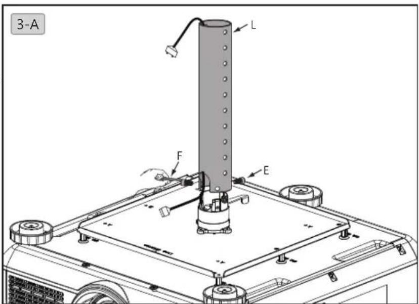
3-A. Length of projector holder can be adjusted in range of 372.8mm\~547.8mm. Place power cable in the inner tube (L), fix it to the projector holder with hexagon screw (M6xL12) (E) and 5mm hexagon wrench (F).
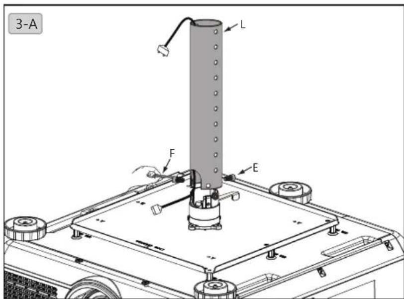
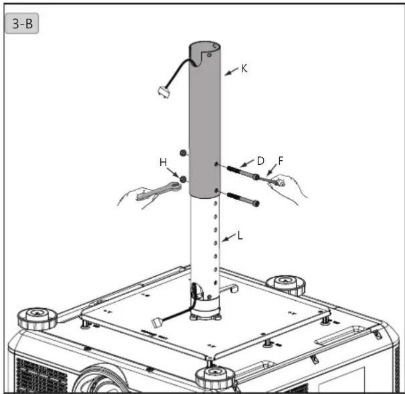
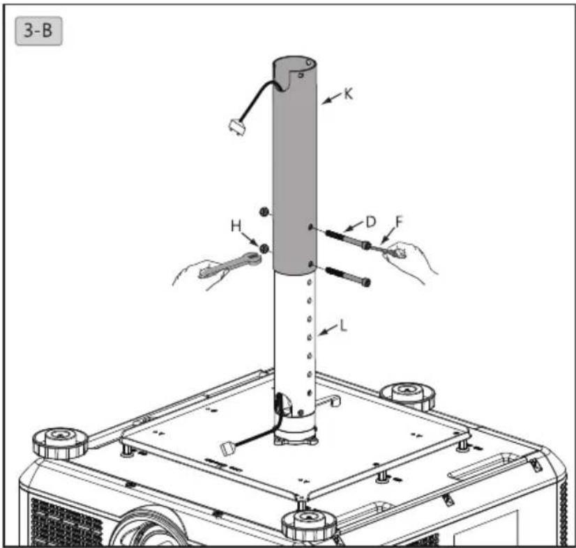
3-B. Pull power cable out of outer tube (K) and connect it to your projector. Assemble the inner tube unit (L and projector) and external tube (K) with 10mm and 5mm wrenches (F) and bolt (D) and nut (H).
Installation steps
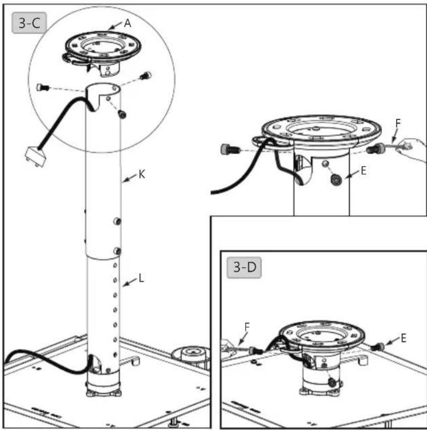
3-C. Fasten inner and outer tube (K+L) and ceiling bracket (A) with hexagon screw (M6xL12) (E) and 5mm wrench (F).
3-D. Set projector length to 98mm. Fasten ceiling bracket (A) and projector holder with hexagon screw (M6xL12) (E) and 5mm wrench (F).
English
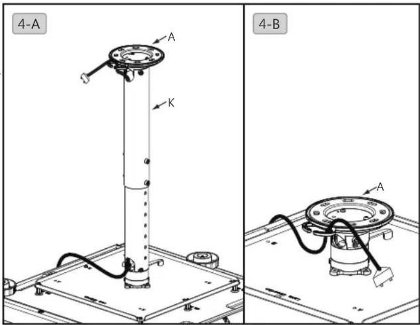
4. Cable management
4-A. Pull power cable from top of external tube (K) to fix it to the ceiling bracket (A).
4-B. Pull power cable through ceiling bracket (A).
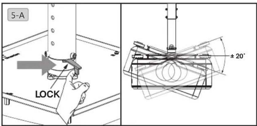
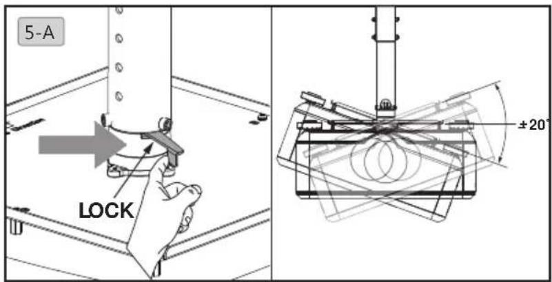
5. Adjust projector angle
5-A. Release the handle, move projector holder to desired angle, push the handle backward to lock it up afterwards.

安全警告
natural_image
Simple line drawing of a mechanical component with a central hub and four mounting holes (no text or symbols)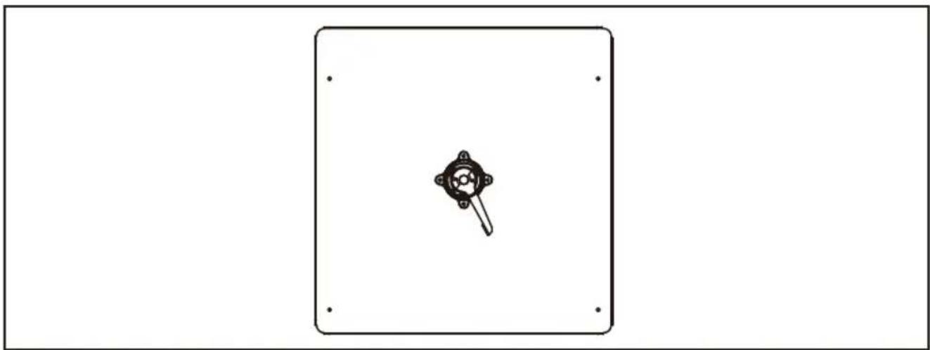
natural_image
Simple line drawing of a mechanical component inside a rectangular frame (no text or symbols)安裝步驟
1. 安装吊架在天花板上

安裝步驟
4.電纜管理
注意
natural_image
Simple line drawing of a mechanical component inside a rectangular frame (no text or symbols)設置手順
1. 天井にハンガーを設置します

設置手順
日本語
4. ケーブル管理
5. 必須角度を調整する
natural_image
Simple line drawing of a mechanical component inside a rectangular frame (no text or symbols)

Warnung
natural_image
Simple line drawing of a mechanical component inside a rectangular frame (no text or symbols)Montageschritte
Montageschritte
4.Kabelführung
natural_image
Black metal hammer with a curved handle (no text or symbols visible)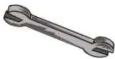
natural_image
Simple line drawing of a mechanical component with a central hub and four mounting holes (no text or symbols)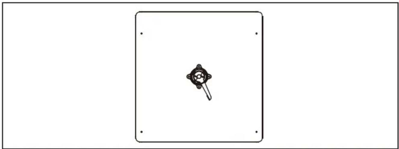
natural_image
Simple line drawing of a mechanical component inside a rectangular frame (no text or symbols)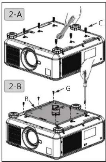

Advertrencias
natural_image
Simple line drawing of a mechanical component with a central hub and four mounting holes (no text or symbols)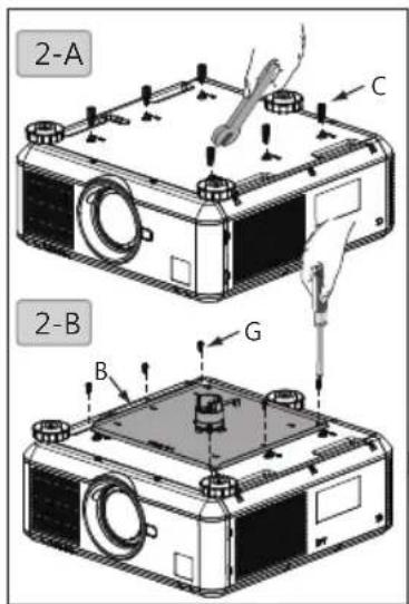
Español

Внимание
natural_image
Two types of screwdrivers shown side by side: a standard screwdriver and a sharpened pencil (no text or symbols visible)natural_image
Simple line drawing of a mechanical component with a central hub and four mounting holes (no text or symbols)Пошаговая установка


Пошаговая установка
4. Прокладка кабеля
natural_image
Simple line drawing of a mechanical component inside a rectangular frame (no text or symbols)43配件包/安装所需工具/钻孔位置
安装步骤
1. 安装吊架在天花板上
安装步骤
簡体中文
4.理线
5.调整投影机角度
Avisos de segurança
natural_image
Black metal hammer with curved handle and flat blade (no text or symbols)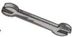
1. Berbequim eléctrico
2. Broca
3. Martelo
4. Chave: 8 mm/10 mm
5. Chave de fendas Philips
6. Lápis
natural_image
Simple line drawing of a mechanical component with a central hub and four mounting holes (no text or symbols)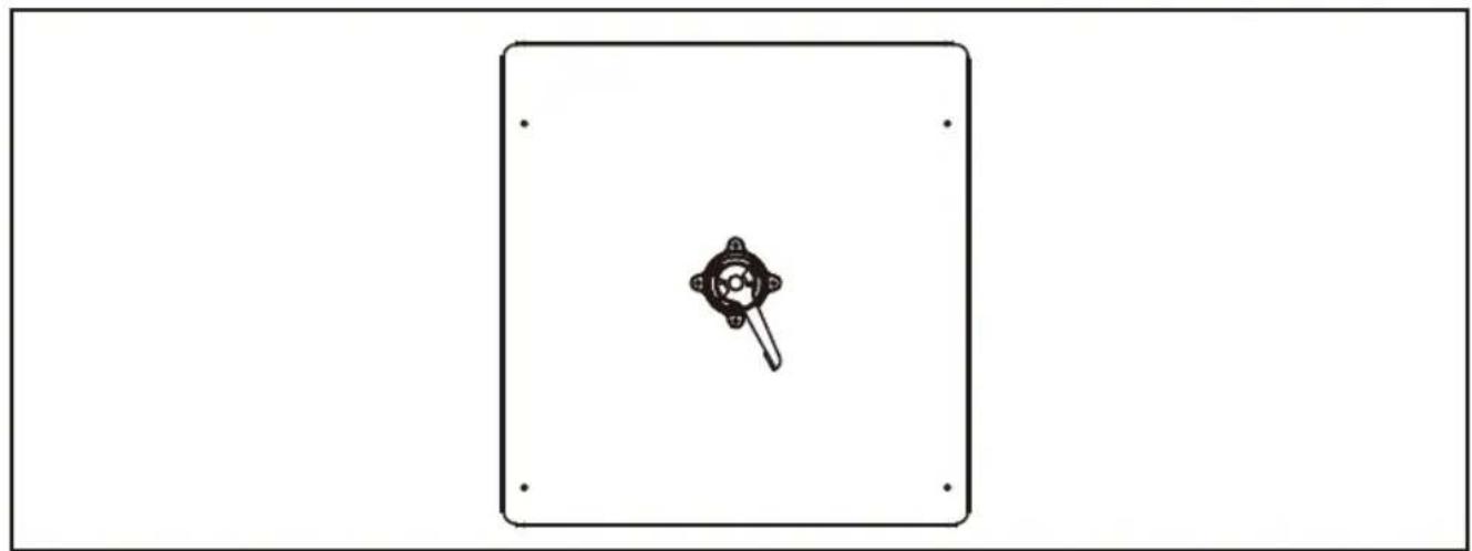
natural_image
Simple line drawing of a device with a central knob and mounting holes, enclosed in a rectangular frame (no text or symbols)

4. Gestão do cabos
5. Ajustar o ângulo do projector

안전 경고
natural_image
Illustration of five different hand tools: drill, hammer, wrench, screwdriver, and pencil (no text or labels present)natural_image
Simple line drawing of a mechanical component with a central hub and four mounting holes (no text or symbols)설치 단계
1. 행거를 천장에 설치

설치 단계
단요
4.케이블 관리
5. 프로젝터 각도 조절
natural_image
Simple line drawing of a mechanical component with a central hub and four mounting holes (no text or symbols)
natural_image
Simple line drawing of a mechanical component inside a rectangular frame (no text or symbols)Installationssteg
Installationssteg
4.Sladden
- Specifications
- Length
- Adjustment angle
- Accessory pack
- Tools needed for installation
- Bore location
- Installation steps
- Install the hanger to your ceiling
- Install projector holder to the projector
- Select length of projector holder
- Cable management
- Adjust projector angle
- 安全警告
- 安裝步驟
- 安装吊架在天花板上
- 4.電纜管理
- 注意
- 設置手順
- 天井にハンガーを設置します
- ケーブル管理
- 必須角度を調整する
- Warnung
- Montageschritte
- 4.Kabelführung
- Advertrencias
- Внимание
- Пошаговая установка
- Прокладка кабеля
- 安装步骤
- 4.理线
- 5.调整投影机角度
- Avisos de segurança
- Gestão do cabos
- Ajustar o ângulo do projector
- 안전 경고
- 설치 단계
- 행거를 천장에 설치
- 4.케이블 관리
- 프로젝터 각도 조절
- Installationssteg
- 4.Sladden
Brand : BENQ
Model : X12000
Category : Projector