
XTR500 - Loudspeaker GEMINI - Free user manual and instructions
Find the device manual for free XTR500 GEMINI in PDF.
| Product type | Amplified 2.1 sound system (active subwoofer + 2 passive satellites) |
| Brand and model | Gemini XTR500 |
| Total RMS power | 400 W (230 W subwoofer + 2x85 W satellites) |
| Program power (PGM) | 800 W |
| Frequency response | Subwoofer: 32 Hz – 100 Hz; Satellites: 100 Hz – 20 kHz |
| Maximum sound level | 120 dB SPL continuous |
| Speakers | Subwoofer: 15" (38 cm); Satellite: 10" (25 cm) + 1" compression driver |
| Dimensions (subwoofer) | 680 x 580 x 525 mm |
| Total net weight | 51 kg |
| Power supply | 220-240 V / 50 Hz (voltage selector) |
| Audio inputs | 2 balanced inputs per channel: XLR (pin 2 hot, pin 3 cold) and 6.35 mm stereo/mono jack |
| Amplified outputs | 2 Speakon outputs (for satellites), cables included |
| Controls | Sensitivity/volume potentiometers per channel; Ground/Lift switch |
| Ventilation | Variable speed fan |
| Finish | High-resistance black granite paint, metal grille |
| Included accessories | Amplified subwoofer, 2 XTR-SAT satellites, 2 Speakon cables (5 m), power cord |
| Maintenance and cleaning | Clean with a slightly damp cloth; do not use solvents or chemicals |
| Safety | Do not disassemble the device; no user-serviceable parts; disconnect before any intervention |
| Warranty | 1 year (subject to local conditions) |
| Recycling | Do not dispose of with household waste; take to a collection point for electronic devices |
Frequently Asked Questions - XTR500 GEMINI
User questions about XTR500 GEMINI
0 question about this device. Answer the ones you know or ask your own.
Ask a new question about this device
Download the instructions for your Loudspeaker in PDF format for free! Find your manual XTR500 - GEMINI and take your electronic device back in hand. On this page are published all the documents necessary for the use of your device. XTR500 by GEMINI.
USER MANUAL XTR500 GEMINI
USA: UK: Spain: France: Germany:
Kemal Suresh Products Co., Ltd.
Merck Pharmaceuticals Limited
Merck Laboratories
Dade Behring, Inc.
Baltimore, MD 20516
Tel: 204-387-9433
Fax: 204-387-9433
E-mail: k.suresh@kpmg.com
In the US. For exposure problems with this unit, please go to http://www.gensortrend.com/portal or call 1-753-9468066 to be Canadian Consumer Service. This service is not meant to express its views on health risks, genetic standards before products with a real-time warning card or radio product. For more details of the product's use in general (including safety information), please visit www.gensortrend.com.
XTR-500
CAUTION: This product satisfies FCC regulations when shielded cables and connectors are used to connect the unit to other equipment. To prevent electromagnetic interference with electric appliances such as radios and televisions, use shielded cables and connectors for connections.
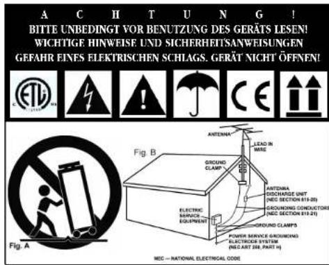
The exclamation point within an equilateral triangle is intended to alert the user to the presence of important operating and maintenance (servicing) instructions in the literature accompanying the appliance.
The lightning flash with arrowhead symbol, within an equilateral triangle, is intended to alert the user to the presence of uninsulated "dangerous voltage" within the product's enclosure that may be of sufficient magnitude to constitute a risk of electric shock to persons.
READ INSTRUCTIONS: All the safety and operating instructions should be read before the product is operated.
REtain INSTRUCTIONS: The safety and operating instructions should be retained for future reference.
HEED WARNINGS: All warnings on the product and in the operating instructions should be adhered to.
FOLLOW INSTRUCTIONS: All operating and use instructions should be followed.
Cleansing: The product should be cleaned only with a polishing cloth or a soft dry cloth. Never clean with furniture wax, benzine, insecticides or other volatile liquids since they may corrode the cabinet.
ATTACHMENTS: Do not use attachments not recommended by the product manufacturer as they may cause hazards.
WATER & MOISTURE: Do not use this product near water, for example near a bathtub, wash bowl, kitchen sink, or laundry tub; in a wet basement; or near a swimming pool; and the like.
ACCESSORIES: Do not place this product on an unstable cart, stand, tripod, bracket, or table. The product may fall, causing serious injury to a child or adult, and serious damage to the product. Use only with a cart, stand, tripod, bracket, or table recommended by the manufacturer, or sold with the product. Any mounting of the product should follow the manufac
turer's instructions, and should use a mounting accessory recommended by the manufacturer.
CART: A product and cart combination should be moved with care. Quick stops, excessive force, and uneven surfaces may cause the product and cart combination to overturn. See FIGURE A.
VENTILATION: Slots and openings in the cabinet are provided for ventilation and to ensure reliable operation of the product and to protect it from overheating, and these openings must not be blocked or covered. The openings should never be blocked by placing the product on a bed, sofa, rug, or other similar surface. This product should not be placed in a built-in installation such as a bookcase or rack unless proper ventilation is provided or the manufacturer's instructions have been adhered to.
POWER SOURCES: This product should be operated only from the type of power source indicated on the marking label. If you are not sure of the type of power supply to your home, consult your product dealer or local power company.
LOCATION: The appliance should be installed in a stable location.
NON-USE PERIODS: The power cord of the appliance should be unplugged from the outlet when left unused for a long period of time. GROUNDING OR POLARIZATION:
-
If this product is equipped with a polarized alternating current line plug (a plug having one blade wider than the other), it will fit into the outlet only one way. This is a safety feature. If you are unable to insert the plug fully into the outlet, try reversing the plug. If the plug should still fail to fit, contact your electrician to replace your obsolete outlet. Do not defeat the safety purpose of the polarized plug.
-
If this product is equipped with a three-wire grounding type plug, a plug having a third (grounding) pin, it will only fit into a grounding type power outlet. This is a safety feature. If you are unable to insert the plug into the outlet, contact your electrician to replace your obsoletc outlet. Do not defeat the safety purpose of the grounding type plug.
POWER-CORD PROTECTION: Power-supply cords should be routed so that they are not likely to be walked on or pinched by items placed upon or against them, paying particular attention to cords at plugs, convenience receptacles, and the point where they exit from the product.
OUTDOOR ANTENNA GROUNDING: If an outside antenna or cable system is connected to the product, be sure the antenna or cable system is grounded so as to provide some protection against voltage surges and built-up static charges. Article 810 of the National Electrical Code, ANSI/NFPA 70, provides information with regard to proper grounding of the mast and supporting structure, grounding of the lead-in wire to an antenna discharge unit, size of grounding conductors, location of antenna-discharge unit, connection to grounding electrodes, and requirements for the grounding electrode. See Figure B.
LIGHTNING: For added protection for this product during a lightning storm, or when it is left unattended and unused for long periods of time, unplug it from the wall outlet and disconnect the antenna or cable system. This will prevent damage to the product due to lightning and power-line surges.
POWER LINES: An outside antenna system should not be located in the
vicinity of overhead power lines or other electric light or power circuits, or where it can fall into such power lines or circuits. When installing an outside antenna system, extreme care should be taken to keep from touching such power lines or circuits as contact with them might be fatal.
OVERLOADING: Do not overload wall outlets, extension cords, or integral convenience receptacles as this can result in a risk of fire or electric shock. OBJECT & LIQUID ENTRY: Never push objects of any kind into this product through openings as they may touch dangerous voltage points or short-out parts that could result in a fire or electric shock. Never spill liquid of any kind on the product.
SERVICING: Do not attempt to service this product yourself as opening or removing covers may expose you to dangerous voltage or other hazards. Refer all servicing to qualified service personnel.
DAMAGE REQUIRING SERVICE: Unplug this product from the wall outlet and refer servicing to qualified service personnel under the following conditions:
-
When the power-supply cord or plug is damaged.
-
If liquid has been spilled, or objects have fallen into the product.
-
If the product has been exposed to rain or water.
-
If the product does not operate normally by following the operating instructions, Adjust only those controls that are covered by the operating instructions as an improper adjustment of other controls may result in damage and will often require extensive work by a qualified technician to restore the product to its normal operation.
-
If the product has been dropped or damaged in any way.
-
When the product exhibits a distinct change in performance, this indicates a need for service.
REPLACEMENT PARTS: When replacement parts are required, be sure the service technician has used replacement parts specified by the manufacturer or have the same characteristics as the original part. Unauthorized substitutions may result in fire, electric shock, or other hazards.
SAFETY CHECK: Upon completion of any service or repairs to this product, ask the service technician to perform safety checks to determine that the product is in proper operating condition.
WALL OR CEILING MOUNTING: The product should not be mounted to a wall or ceiling.
HEAT: The product should be situated away from heat sources such as radiators, heat registers, stoves, or other products (including amplifiers) that produce heat.
DISPOSAL: This product shall not be treated as household waste. Instead it shall be handed over to the applicable collection point for the recycling of electrical and electronic equipment. By ensuring this product is disposed of correctly, you will help prevent potential negative consequences for the environment and human health, which could otherwise be caused by inappropriate waste handling of this product. The recycling of materials will help to conserve natural resources. For more detailed information about recycling of this product, please contact your local city office, your household waste disposal service or the shop where you purchased the product.
XTR-SAT satellite speakers
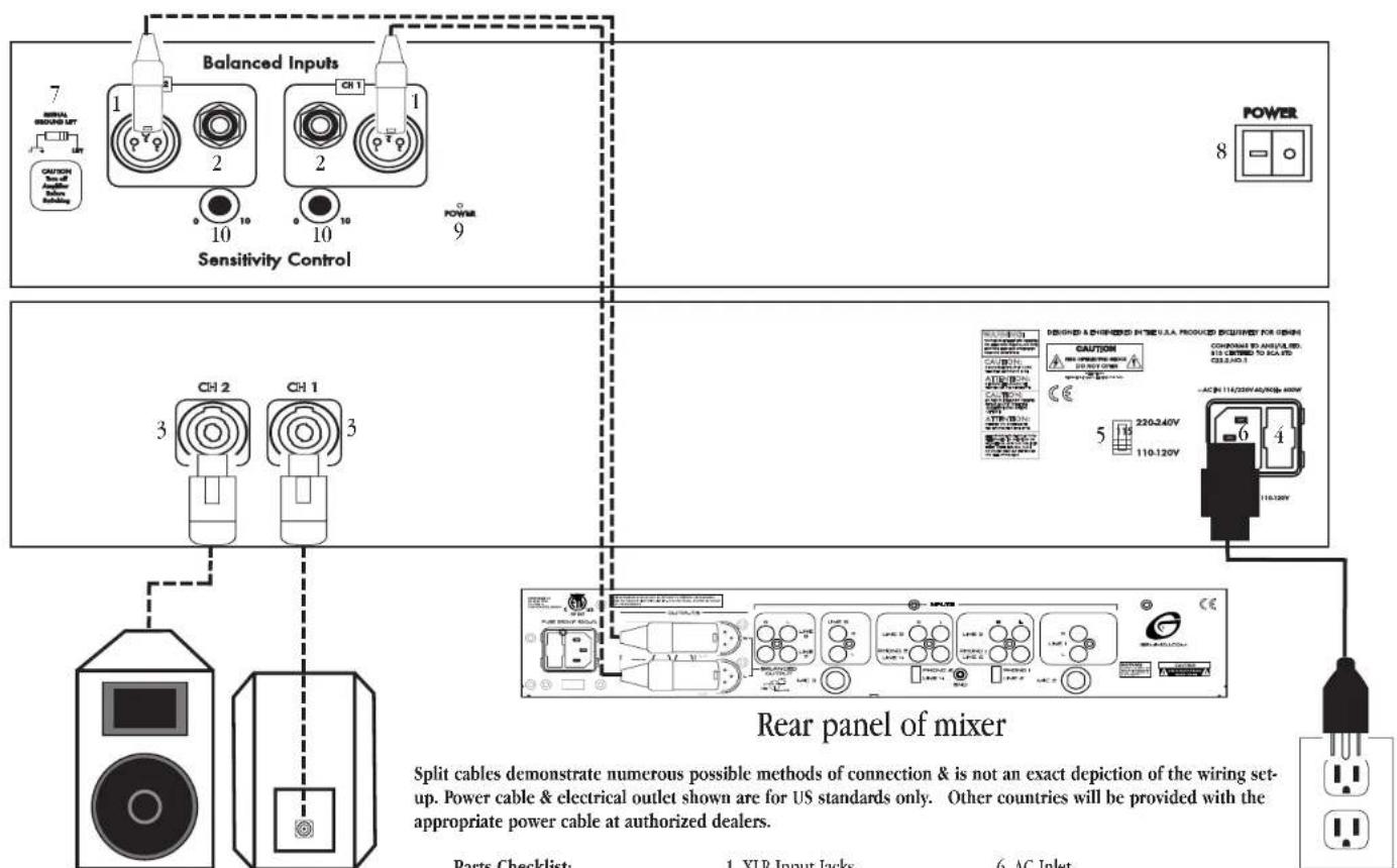
Parts Checklist:
Subwoofer w/Amplifier
2 × 10^ Satellite Speakers
2 x 5m (16.4 ft) Speakon Cables
Power Cable
- XLR Input Jacks
2.1/4n Phono Input Jacks - Speakon Outputs
- Fuse
-
AC Line Voltage Selector Switch
-
AC Inlet
- Signal Ground Lift Switch
- Power Switch
- Power LED
- Sensitivity / Volume Controls
Congratulations on your purchase of an XTR-500 speaker system engineered & manufactured by Gemini Sound Products. This state of the art speaker system is backed by a one-year warranty. The XTR-500 offers ultimate fidelity, power handling, and an array of features that makes it a highly versatile, compact, self-contained & powered speaker system.
FEATURES:
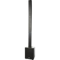
- 2 X'TR-SAT '10" "trapezoidal loudspeakers & 15" powered subwoofer
Efficient MDF Bandpass subwoofer enclosure w/ 35mm Standmount cap and wheels - 3-channel power amplifier & active crossover built-in to subwoofer
- 230 watts RMS on subwoofer channel (Satellite Freq. Response: 32Hz to 100Hz)
-85 watts RMS per satellite channel (Subwoofer Freq. Response: 100Hz to 20 kHz) - 400 watts total RMS and 800 watts peak power
- 120dB total continuous SPL
Individual channel Sensitivity:Volume controls
Balanced XLR and 1/4" inputs - Speakon outputs for satellite channels (Cables Included)
Variable speed fan
Full protective metal grill - Hard wearing black painted finish with rubber feet
- Speaker stands not included
CAUTIONS:
- All operating instructions should be read before using this equipment.
- To reduce the risk of electrical shock, do not open the unit. There are NO USER REPLACEABLE PARTS INSIDE, Please refer servicing to a qualified Gemini Sound Products service technician. In the USA: If you experience problems with this unit, please call 1 (732) 738-9003 for Gemini Customer Service. Do not attempt to return this equipment to your dealer.
- Do not expose this unit to direct sunlight or to a heat source such as a radiator or stove.
- This unit should be cleaned only with a damp cloth. Avoid solvents or other cleaning detergents.
- When moving this equipment, it should be placed in its original carton and packaging. This will reduce the risk of damage during transit.
- DO NOT EXPOSE THIS UNIT TO RAIN OR MOISTURE
- DO NOT USE ANY SPRAY CLEANER OR LUBRICANT ON ANY CONTROLS OR SWITCHES.
CONNECTIONS:
INPUT SECTION: There are two parallel input connectors (one female XLR and one 1/4 jack) per channel. Either can be used as an input or as a
link to chain amplifiers.
1. XLR INPUT JACKS: XLR INPUT JACKS (1) electronically balanced inputs accept a standard XLR male connector. Pin 1 = shield/ground, pin 2 = hot or positive (+) and pin 3 = cold or negative (-).
2. 1 / 4^ PHONO INPUT JACKS: 1 / 4^ PHONO INPUT JACKS (2) accept a balanced as well as an unbalanced line. The unbalanced line uses a standard tip-sleeve connection. The tip is positive and the sleeve is negative/ground. The balanced line uses a tip-ring-sleeve connection. Tip = hot or positive (+), ring = cold or negative (-), and sleeve = shield/ground.
3. SENSITIVITY/VOLUME CONTROLS: SENSITIVITY/VOLUME CONTROLS (10) control the input levels for each channel of the 2 satellite speakers. The volume level of the subwoofer is controlled automatically to match the volume levels of the satellite speakers. It will always maintain a perfect balance to give you incredible sound quality!
4. SIGNAL GROUND LIFT SWITCH: SIGNAL GROUND LIFT SWITCH (7) is used to lift the balanced input connectors' ground/shield from the amplifier's ground. When the signal ground lifted, the sound source disconnects from the amplifier's ground preventing ground loops which can generate hum and noise. Scc the Signal Ground Lift Switch Instructions for more detail.
OUTPUT SECTION: Disconnect unit from the AC power source before making any connections.
- SPEAKON OUTPUTS (3): The speaker output connectors are Speakon™ connectors that will accept cables with Speakon™ connectors. The subwoofer is already connected internally, so you don't have to worry about connecting it to the amplifier.
AC POWER SECTION:
- POWER SWITCH (8): turns the unit on and off.
- POWER LED (9): the power LED lights when the power is on.
- Fuse4: replace with proper type and rating.
- AC INT (6) is used to attach the power cord to the unit.
- AC LINE VOLTAGE SELECTOR SWITCH (5) allows reconfiguring amplifier for either 110-120V or 220-240V AC lines.
OPERATION:
-
STEREOPOperation: The unit has two channels for stereo operation. Each channel provides a separate signal at the speaker outputs. The following instructions are for use with 8 ohm speakers of matched power ratings. We suggest only using the speakers that come with the unit.
-
With the power OFF, connect your input cables from your music source (such as your mixer) to the Channel 1 and Channel 2 INPUTS using the XLR INPUT JACKS (1) or 1/4^ PHONO INPUT JACKS (2).
- Connect your speakers to the Channel 1 and Channel 2 SPEAKON OUT-PTS (3).
- With the SENSITIVITY/VOLUME CONTROLS (10) of both channels set to zero
fully counter clockwise), turn the POWER SWITCH (8). ON. Okay, now try playing some music and/or talking into your microphone, and set the level of your input as high as you think you'll need it. This way it will be as high above the amplifier's noise floor as possible so you'll get the best possible sound with the least amount of noise. Now play some music and listen for audible distortion. If you do hear distortion decrease the output level using the SENSITIVITY/VOLUME CONTROLS (10).
5. MONO OPERATION: Connect your MONO signal to the Channel 1 input (1 or 2). Now create a link by connecting the remaining Channel 1 input to a Channel 2 input (1 or 2) using a standard balanced cable (may be purchased separately). You can adjust the level of each satellite speaker using its channel's SENSITIVITY/VOLUME CONTROL (10).
6. USING THE SIGNAL GROUND LIFT SWITCH: Depending on how your sound system is hooked up, sometimes applying the ground will create a quieter signal path. Sometimes lifting the ground can eliminate ground loops and that annoying hum to give you quieter and cleaner overall sound.
- With the power amp ON, listen to the system in idle mode (no music or signal) with the ground ON. The SIGNAL GROUND LIFT SWITCH (7) will be in the left position.
- Turn the power OFF before moving the SIGNAL GROUND LIFT SWITCH (7). Now lift the ground by moving the SIGNAL GROUND LIFT SWITCH (7) to the right. Turn the power back ON and listen to determine which position makes the overall sound quieter with the least amount of noise and hum.
CAUTION: DO NOT DISCONNECT THE AC GROUND ON THE POWER AMPLIFIER IN ANY WAY. THIS CAN BE VERY HARDOUS!
SETUP:
There are various ways to set up this system:
BASICSETUP
This is your basic setup, perfect for small parties and venues. The ideal location for your subwoofer is close to a wall or in a corner. This will give you the fullest bass response. Your 2 satellite speakers can be placed up on stands on each side (stands must be purchased separately).
TWO-SYSTEM SETUP:
This setup is perfect for larger venues. This setup requires 2 XTR-500 systems. This will give you a total of 800 watts RMS! Place a subwoofer on each side to the left and right. Using the high-hat hardware and connecting polc (which can be purchased separately), place the polc in the high-hat socket on the subwoofer, and a satellite speaker on top of the polc. The 2 remaining satellite speakers may be used as either floor monitors, or placed on stands elsewhere in the room giving you a louder and fuller sound. Each speaker system in this setup must be used in MONO mode (see Mono section). Connect the system that is on the left side of the audience to the LEFT channel of your mixer, and the system that is on the right side of the audience to the RIGHT channel of your mixer.
SPECIFICATIONS:
Subwoofer XTR-500SUB:
Amplifier's Output Power: 230 Watts RMS on subwoofer channel
Frequency response: 32 Hz - 100 Hz
Components: 15" wooler
Dimensions: 26.75"W x 22.75"D x 20.75"H (680 x 580 x 525mm)
Weight: 71 lbs (34 kg)
Satellites XTR-SAT:
Amplifier's Output Power: 2.x 85 Watts RMS on satellite channels
Frequency response: 100 Hz - 20 kHz
Components: 10" woofer
. Compression driver with 1" diaphragm
Dimncions: 12.5"W x 9"D x 18"H (318 x 229 x 158mm)
Weight: 18 lbs (8.5 kg) each
Total System:
Amplifier's Output Power: 400 Watts RMS total combined power
Maximum SPL. continuous: 120 dB
Sensitivity 1 Vrms
Input Impedance: 10 kOhm unbalanced/20 kOhm balanced
Total Weight: 112 lbs (51 kg)
AC Power Requirements: 110-120 V/60 Hz; 220-240 V/50 Hz
SPECIFICATIONS AND DESIGN ARE SUBJECT TO CHANGE WITHOUT NOTICE FOR PUR
POSE OF IMPROVEMENT.
*The stated warranty does not affect statutory local warranties
NOTES:
<5>

XTR-500
Dimenions: 12.5"W x 9"D x 18"H (318 x 229 x 458mm)
Poids net: 18 lbs (8.5 kg) each
Systeme complet:
Puisance de I amplificateur: 400 Watts RMS total combined power


Brand : GEMINI
Model : XTR500
Category : Loudspeaker