EcoBoost MPPT - Solar panel Morningstar - Free user manual and instructions
Find the device manual for free EcoBoost MPPT Morningstar in PDF.

| Product Type | MPPT Solar Charge Controller |
| Brand | Morningstar |
| Model | EcoBoost MPPT (EB-MPPT-20/30/40) |
| Nominal Battery Voltage | 12 V or 24 V (auto-detection or manual selection) |
| Maximum PV Open Circuit Voltage | 120 V |
| Maximum Charge Current | 20 A (EB-20), 30 A (EB-30), 40 A (EB-40) |
| Maximum PV Power | 300/600 W (12/24 V) for EB-20, 400/800 W for EB-30, 500/1120 W for EB-40 |
| Conversion Efficiency | 97.3% (peak value) |
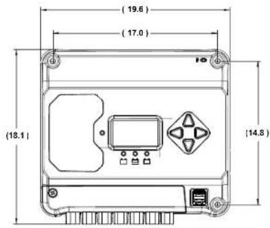
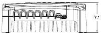
| Dimensions (L x W x H) | 19.6 x 18.1 x 7.1 cm |
| Weight | 1.4 kg |
| Charging Algorithm | 4 stages: bulk, absorption, float, equalization |
| Technology | TrakStar MPPT (Maximum Power Point Tracking) |
| USB Charging Ports | 2 USB-A ports for auxiliary charging |
| Display | Digital LCD screen (meter model) or LED indicators |
| Remote Temperature Sensor (RTS) | Optional, highly recommended for accurate compensation |
| Protections | Reverse polarity, PV/load short circuit, overvoltage, overtemperature, etc. |
| Power Consumption | < 25 mA (without meter), < 40 mA (with meter) |
| Operating Temperature | -40 °C to +60 °C |
| Warranty | 2 years |
| Certifications | IEC 62109-1, CSA C22.2 No. 107.1, FCC Class B, CE |
Frequently Asked Questions - EcoBoost MPPT Morningstar
User questions about EcoBoost MPPT Morningstar
0 question about this device. Answer the ones you know or ask your own.
Ask a new question about this device
Download the instructions for your Solar panel in PDF format for free! Find your manual EcoBoost MPPT - Morningstar and take your electronic device back in hand. On this page are published all the documents necessary for the use of your device. EcoBoost MPPT by Morningstar.
USER MANUAL EcoBoost MPPT Morningstar
Solar Charging System Controller
Installation, Operation and Maintenance Manual
For the most recent manual revisions, see the version at: www.morningstarcorp.com

MORNINGSTAR
ESSENTIAL SERIES
World's Leading Solar Controllers & Inverters
www.morningstarcorp.com
MODELS
DIMENSIONS (centimeters)
SPECIFICATION SUMMARY
| EB-MPPT-20 | EB-MPPT-30 | EB-MPPT-40 | |
| Nominal Battery Voltage | 12/24V 12/24V | ||
| Max. PV Open-Circuit Voltage* | 120V 120V | ||
| Nominal Max. Input Power** | 300 / 600W 400 / 800W | ||
| Max. Battery Charging Current | 20A 30A 40A | ||
| Rated Load Current | 20A 30A 30A | ||
Array voltage should never exceed this limit
*These power levels refer to the maximum wattage the EcoBoost MPPT can process. Higher power arrays can be used without damaging the controller.
TABLE OF CONTENTS
1.0 Important Safety Instructions.. 1
2.0 General Information.. 5
2.1 Overview 5
2.2 Features 6
2.3 Optional Accessories.. 8
3.0 Installation 9
3.1 General Installation Notes.. 9
3.2 Configuration 11
3.3 Mounting 14
3.4 Wiring 15
4.0 Operation 23
4.1 TrakStar MPPT Technology 23
4.2 Battery Charging Information.. 23
4.3 Load Control Information 26
4.4 LED Indications 28
4.4.1 Power-up 28
4.4.2 Status LED 28
4.4.3 State-of-charge LEDs.. 29
4.5 Alarms.. 29
4.6 Custom Settings.. 31
4.6.1 Adjusting Set-points with Meter Display 31
4.6.2 Meter Display Operation 32
4.6.2.1 Directional Key Use and Operation / Navigating the Meter Map.... 32
4.6.2.2 Adjusting the Meter Display. 32
4.7 Data Logging (future use) 32
4.8 Auxiliary USB Charging.. 33
4.9 Inspection and Maintenance 33
Continued...
....Continued
5.0 Troubleshooting 35
5.1 LED Fault Indications 35
5.2 Battery Charging and Performance Issues.. 39
6.0 Warranty 40
7.0 Technical Specifications 41
8.0 Certifications. 44
1.0 IMPORTANT SAFETY INSTRUCTIONS
SAVE THESE INSTRUCTIONS.
This manual contains important safety, installation, operating and maintenance instructions for the EcoBoost MPPT solar controller.
The following symbols are used throughout this manual to indicate potentially dangerous conditions or mark important safety instructions:

WARNING:Indicates a potentially dangerous condition. Use extreme caution when performing this task.

CAUTION: Indicates a critical procedure for safe and proper operation of the controller.

NOTE: Indicates a procedure or function that is important to the safe and proper operation of the controller.
Safety Information
- Read all of the instructions and cautions in the manual before beginning installation.
- There are no user serviceable parts inside the EcoBoost MPPT. Do not disassemble or attempt to repair the controller.

WARNING: Risk Of Electrical Shock.
POWER OR ACCESSORY TERMINALS ARE
ELECTRICALLY ISOLATED FROM DC INPUT, AND MAY BE ENERGIZED WITH HAZARDOUS SOLAR VOLTAGE. UNDER CERTAIN FAULT CONDITIONS, BATTERY COULD BECOME OVER-CHARGED. TEST BETWEEN ALL TERMINALS AND GROUND BEFORE TOUCHING.

WARNING: THE COMMUNICATIONS PORT IS
CONSIDERED TO BE DVC B. AN EXTERNAL
ISOLATOR IS REQUIRED IF IT IS TO BE CONNECTED TO A DVC A CIRCUIT.
- External solar and battery disconnects are required.
- Disconnect all sources of power to the controller before installing or adjusting the EcoBoost MPPT.
- There are no fuses or disconnects inside the EcoBoost MPPT Do not attempt to repair.
Installation Safety Precautions
- Mount the EcoBoost MPPT indoors. Prevent exposure to the elements and do not allow water to enter the controller.
- Install the EcoBoost MPPT in a location that prevents casual contact. The EcoBoost MPPT heatsink can become very hot during operation.
- Use insulated tools when working with batteries.
- Avoid wearing jewelry during installation.
- The battery bank must be comprised of batteries of same type, make, and age.
- IEC 62109 certified for use in negative ground or floating systems only.
- Do not smoke near the battery bank.
- Power connections must remain tight to avoid excessive heating from a loose connection.
- Use properly sized conductors and circuit interrupters.
- This charge controller is to be connected to DC circuits only. These DC connections are identified by the symbol below:

Direct Current Symbol
The EcoBoost MPPT controller must be installed by a qualified technician in accordance with the electrical regulations of the country of installation.
A means of disconnecting all power supply poles must be provided. These disconnects must be incorporated in the fixed wiring.
The EcoBoost MPPT negative power terminals are common, and must be grounded as instructions, local codes, and regulations require.
A permanent, reliable earth ground must be established with connection to the EcoBoost MPPT heatsink.
The grounding conductor must be secured against any accidental detachment.
Battery Safety

WARNING: A battery can present a risk of electrical
k_2 or burn from large amounts of short-circuit
ent, fire, or explosion from vented gases.
Observe proper precautions.

WARNING: Risk of Explosion.
Proper disposal of batteries is required. Do not
dispose of batteries in fire. Refer to locally
regulations or codes for requirements.

CAUTION: When replacing batteries, use properly
sified number, sizes, types, and ratings based on
application and system design.

CAUTION: Do not open or mutilate batteries.
used electrolyte is harmful to skin, and may be
toxic.
Servicing of batteries should be performed, or supervised, by personnel knowledgeable about batteries, and the proper safety precautions.
- Be very careful when working with large lead-acid batteries. Wear eye protection and have fresh water
available in case there is contact with the battery acid.
- Remove watches, rings, jewelry and other metal objects before working with batteries.
- Wear rubber gloves and boots
- Use tools with insulated handles and avoid placing tools or metal objects on top of batteries.
- Disconnect charging source prior to connecting or disconnecting battery terminals.
- Determine if battery is inadvertently grounded. If so, remove the source of contact with ground. Contact with any part of a grounded battery can result in electrical shock. The likelihood of such a shock can be reduced if battery grounds are removed during installation and maintain enance (applicable to equipment and remote battery supplies not having a grounded supply circuit).
- Carefully read the battery manufacturer's instructions before installing / connecting to, or removing batteries from, the EcoBoost MPPT.
- Be very careful not to short circuit the cables connected to the battery.
- Have someone nearby to assist in case of an accident.
- Explosive battery gases can be present during charging. Be certain there is enough ventilation to release the gases.
- Never smoke in the battery area.
If battery acid comes into contact with the skin, wash with soap and water. If the acid contacts the eye, flood with fresh water and get medical attention. - Be sure the battery electrolyte level is correct before starting charging. Do not attempt to charge a frozen battery.
Recycle the battery when it is replaced.
2.0 GENERAL INFORMATION
2.1 Overview
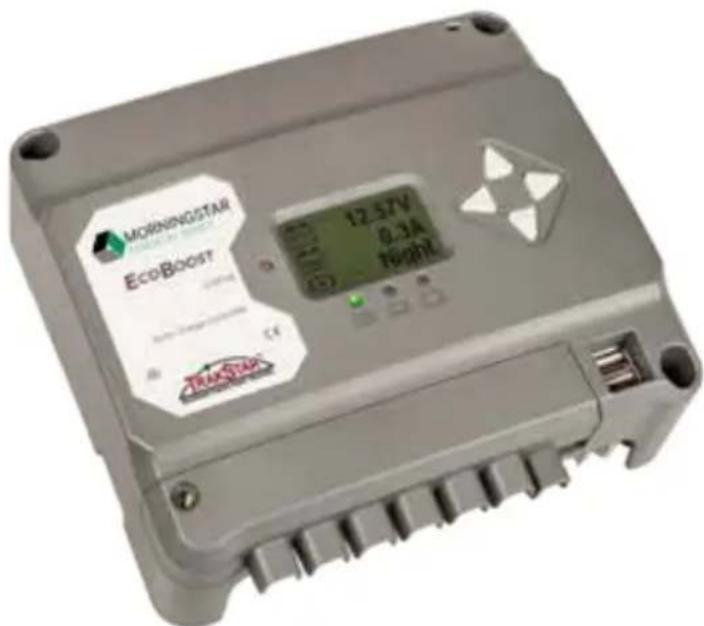
Thank you for choosing the EcoBoost MPPT charge controller with TrakStar™ MPPT Technology. The EcoBoost MPPT is an advanced maximum power point tracking solar battery charger. The controller features a smart tracking algorithm that finds and maintains operation at the power source's peak power point, maximizing energy harvest.
The EcoBoost MPPT battery charging process has been optimized for long battery life and improved system performance. Self-diagnostics and electronic error protections prevent damage when installation mistakes or system faults occur. The controller also features eight (8) adjustable settings switches, several communication ports, and terminals for remote battery temperature and voltage measurement.
Please take the time to read this operator's manual to become familiar the many benefits the EcoBoost MPPT can provide for your PV systems, for example:
- Rated for 12 or 24 volt systems, and 20, 30 or 40 amps of charging current
Fully protected with automatic and manual recovery - Seven standard charging programs selectable with DIP switches
- Continuous self-testing with fault notification
- LED indications and push-button or meter key functions
Power terminal maximum of #6 AWG wire.
Digital meter display options - Optional remote battery temperature sensor
2-year warranty (see Section 6.0)
2.2 Features
The features of the EcoBoost MPPT are shown in Figure 2-1 below. An explanation of each feature is provided below.
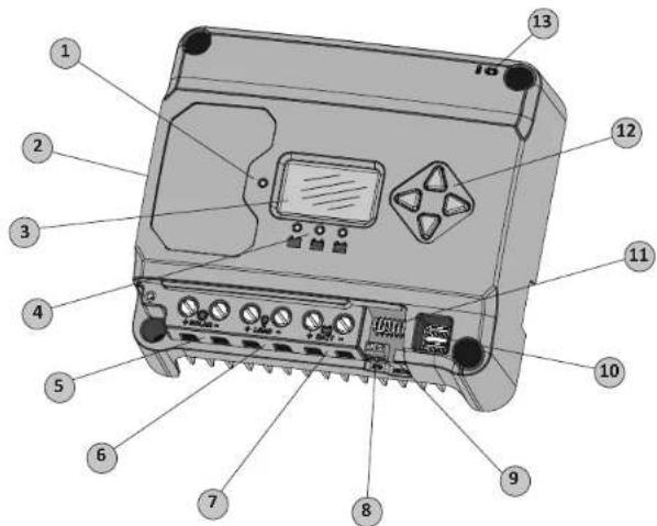
Figure 2-1. EcoBoost MPPT Features
1 - Charging Status / Error LED
Indicates charging and error condition statuses.
2 - Heatsink / Grounding Screw (M4 screw for grounding heatsink) Aluminum heatsink (underneath) to dissipate controller heat (the EcoBoost MPPT is 100% passively cooled for reliability)
3-Meter Display
Digital LCD monitoring and programming display
4-Battery Status/Fault LED Indicators
Three state of charge (SOC) LED indicators show charging status and controller faults
5 - Solar Positive and Negative Terminals
Power connections for Solar (+) and (-) cable terminations
6 - Load Positive and Negative Terminals
Power connections for Load (+) and (-) cable terminations
7 - Battery Positive and Negative Terminals
Power connections for Battery (+) and (-) cable terminations
8 - Remote Temperature Sensor Terminals (RTS)
Connection points for a Morningstar RTS to remotely monitor battery temperature
9 - USB Micro-B Data Port (future use)
Micro-B USB port for (future) data transfer
10 - USB-A Charging Ports
USB-A sockets for charging electronic devices
11 - DIP Switches
Eight (8) settings switches to configure operation of the EcoBoost MPPT
12-Meter Directional Buttons
Used to navigate throughout meter map
13 - Local Temperature Sensor
Compensates charging based on ambient temperature (not used if Remote Temperature Sensor is connected)
2.3 Optional Accessories
The following accessories are available for purchase separately from your authorized Morningstar dealer:
Remote Temperature Sensor (Model: RTS)
The RTS measures battery temperature for accurate temperature compensation and is recommended when the ambient battery temperature differs from the ambient controller temperature by more than 5^ . The standard cable length is 33 ft (10m).

NOTE: The use of a Remote Temperature Sensor is
strongly recommended. Controller location, air flow, and
system power can drastically affect the local temperature sensor reading. An RTS will provide optimal charging performance.
Ground-fault Protection Device (GFPD-150V)
As a safety measure, the GFPD-150V detects power source ground faults and interrupts current.
3.0 INSTALLATION
3.1 General Installation Notes
- Read through the entire installation section first before beginning installation.
- Be very careful when working with batteries. Wear eye protection. Have fresh water available to wash and clean any contact with battery acid.
- Use insulated tools and avoid placing metal objects near the batteries.

WARNING: Equipment Damage or Risk of Explosion
Never install the EcoBoost MPPT in an enclosure with vented/flooded batteries. Battery fumes are flammable and will corrode and destroy the EcoBoost MPPT circuits.

CAUTION: Equipment Damage
When installing the EcoBoost MPPT in an enclosure, ensure sufficient ventilation. Installation in a sealed enclosure will lead to over-heating and a decreased product lifetime.

WARNING: Equipment Damage
The EcoBoost MPPT is designed for negative or floating ground systems ONLY, and is NOT approved for use in a positive ground system. Damage to USB connected devices may result.

WARNING: Equipment Damage
DO NOT connect a laptop PC to the USB data port while the laptop is connected to an AC charger. Damage to the USB port may result.
- Do not install in locations where water can enter the controller.
- Loose power connections and/or corroded wires may result in resistive connections that melt wire insulation, burn surrounding materials, or even cause fire. Ensure tight connections and use cable clamps to secure cables and prevent them from swaying in mobile applications.
- Preset charging profiles are generally designed for lead acid batteries. Custom settings can be used for varied charging requirements (see sections 3.2 and 4.7 for details). Note that some battery types may not be compatible.
- The EcoBoost MPPT battery connection may be wired to one battery, or a bank of batteries. The following instructions refer to a singular battery, but it is implied that the battery connection can be made to either one battery or a group of batteries in a battery bank.
- The EcoBoost MPPT uses self-tapping fasteners, an anodized aluminum heat sink, and conformal coating to protect it from harsh conditions. However, for acceptable service life, extreme temperatures and marine environments should be avoided.
- The EcoBoost MPPT prevents reverse current leakage at night, so a blocking diode is not required in the system.
- The EcoBoost MPPT is designed to regulate ONLY solar (photovoltaic) power. Connection to any other type of power source e.g. wind turbine or generator may void the warranty. However, other power sources can be connected directly to the battery.
- The maximum power terminal wire size is #6 AWG / 16 mm² (solid/multi-strand) or #8 AWG / 10 mm² (fine strand). Use a flathead insulated screwdriver, and torque tightly up to 3.95 Nm.
- Stranded wires to be connected to the EcoBoost MPPT terminals should be prepared first with e.g. clamped copper heads, etc. to avoid the possibility of one conductor free out of the connection screw, and possible contact with the metal enclosure.
WARNING: Solar and battery fuses or DC breakers are required in the system. These protection devices are external to the EcoBoost MPPT controller, and must be a maximum of 25 amps for the EB-20/M, 35 amps for the EB-30/M, and 50 amps for the EB-40/M.
WARNING: Breakers and fuses may require lower ratings than referenced above, so as not to exceed any specific wire ampacity.
WARNING: Minimum over-current protection device interrupt ratings must be 2000A for 12V systems, and 4000A for 24V systems.
3.2 Configuration
The DIP switch block shown in Figure 3.1 below is used to set the operating parameters for the EcoBoost MPPT.
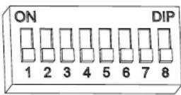
Figure 3.1. DIP Switch Block to set charging parameters
Switch 1: Load / Lighting
| Mode Switch1 | |
| Normal OFF | |
| Lighting ON | |
With DIP 1 ON, the EcoBoost MPPT will follow a dusk-to-dawn lighting schedule.
Switches 2, 3: System Voltage
Three (3) system voltage configurations are available as shown in the table below:
| System Voltage S | switch 2 Switch 3 |
| Auto OFF OFF | |
| 12 OFF ON | |
| 24 ON OFF |
NOTE: Before connecting the battery, measure the open-circuit voltage. It must be over 10 volts to start the controller. If the system voltage Settings Switches are set to Auto-detect, battery voltage over 15.5V will be detected as a 24V nominal battery, and the unit will charge accordingly. The 12/24V auto selection is only done at start-up, and the detected system voltage will never change during operation.
Generally, the specific system voltage is known, and it is best to set DIPs 2,3 accordingly; the auto-detect setting should be used only in rare circumstances.
Switches 4, 5, 6: Battery Type Selection
Preset EcoBoost MPPT battery charging options are shown in table 3-1 below. All voltage settings listed are for nominal 12 volt batteries.
Multiply the voltage settings by two (2) for 24 volt systems.

NOTE: These settings are general guidelines for use at the operator's discretion. The
EcoBoost MPPT can be programmed to satisfy a wide range of charging parameters. Consult the battery manufacturer for optimal battery charge settings.
| DP Switch Settings 4-5-54 | Battery Type | Absorp. Stage (volts) | Flout Stage (volts) | Equilibration Stage (volts) | Absorp. Time (min) | Equilibration Time (min) | Equilibration Interval (days) | IVD (volts) | LVR (volts) |
| off-off-off | - Sealed* 14.00 | 13.50 | 150 | 11.50 | 12.60 | ||||
| off off on | 2 - Sealed* | 14.15 | 13.50 | 14.40 | 150 | 60 | 120 | 28 | 11.30 |
| off-on-off | 3 - Sealed* | 14.30 | 13.50 | 14.60 | 150 | 60 | 120 | 28 | 11.50 |
| off on on | 4 AC/IM/Flooded | 14.40 | 13.50 | 15.10 | 160 | 120 | 160 | 28 | 11.70 |
| on-off-off | 5 - Flouted | 14.60 | 13.50 | 15.30 | 180 | 120 | 180 | 28 | 11.90 |
| on off on | 6 - Flooded | 14.70 | 13.50 | 15.40 | 180 | 180 | 240 | 28 | 12.10 |
| on-off-off | 7 - I-6 | 15.40 | 13.40 | 16.00 | 180 | 180 | 240 | 14 | 12.30 |
| on-on-on | 8 - Custom | Custom | Custom | Custom | Custom | Custom | Custom | Custom | Custom |
- "Sealed" battery type includes gel and AGM batteries
Table 3.1. Battery charging settings for each selectable battery type
Switch 7: Battery Equalization
Switch 8: Reserved for Future Use
| Mode | Switch 7 |
| Manual Equalization | OFF |
| Auto Equalization | ON |
3.3 Mounting
Inspect the controller for shipping damage. Mount the EcoBoost MPPT to a vertical surface (4-#8 self-tapping screws are included). Tighten the mounting screws, using care not to crack the plastic case. Do not install directly over an easily combustible surface since the heat sink may get hot under certain operating conditions.

NOTE: The heat sink must be in a vertical position (fins and down).
For proper air flow, allow at least 15cm (6 in) of space above and below the controller, and 50~mm (2 in) at the sides - see Figure 3-2 below. Install in an area protected from direct rain and sun.
If the controller is installed in an enclosure, some ventilation is recommended. Do not locate in an enclosure where battery gases can accumulate.
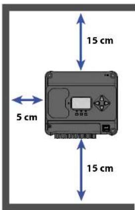
Figure 3-2. Proper Clearances for Passive Cooling
3.4 Wiring
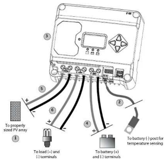
Figure 3-3. Wiring the EcoBoost MPPT
REFER TO FIGURE 3.3 WHEN USING THE WIRING INSTRUCTIONS BELOW.
STEP 1: Check Controller Limitations
Verify that the highest temperature compensated solar array open-circuit voltage (Voc), and load current do not exceed the ratings of the EcoBoost MPPT version being installed.
Multiple controllers can be installed in parallel on the same battery bank to achieve greater total charging current. In this type of system, each EcoBoost MPPT must have its own solar array. The load terminals of multiple controllers can only be wired together if the total load draw does not exceed the nameplate current of the LOWEST rated controller.
STEP 2: Remote Temperature Sensor
WARNING: Risk of Fire. If no Remote Temperature Sensor (RTS) is connected, use the EcoBoost MPPT within 3m (10 ft) of the batteries. Internal Temperature Compensation will be used if the RTS is not connected. Use of the RTS is strongly recommended.
All charging settings are based on 25^ (77^) . If the battery temperature varies by 5^ , the charging setting will change by 0.15 Volts for a 12 Volt battery. This is a substantial change in the charging of the battery, and the use of the
optional Remote Temperature Sensor (RTS) is recommended to adjust charging to the actual battery temperature. The RTS can be added at any time after the system has been installed.
Connect the (+) and (-) RTS wires to the 2-position terminal located below the DIP switches (see figure 3.3).
The RTS is supplied with 10m of 22 AWG (0.34mm^2) cable. There is no polarity, so either wire (+ or -) can be connected to either screw terminal. The RTS cable may be pulled through conduit along with the power wires. Tighten the connector screws to 0.56Nm of torque. Separate installation instructions are provided inside the RTS bag.
WARNING: Equipment Damage
Never place the temperature sensor inside a battery cell. Both the RTS and the battery will be damaged.

CAUTION: The EcoBoost MPPT will use the local temperature sensor for compensation if the RTS is not used.
NOTE: The RTS cable may be shortened if the full length is not needed. Be sure to reinstall
choke on the end of the RTS if a length of cable is removed. This choke ensures compliance with electromagnetic emissions standards.
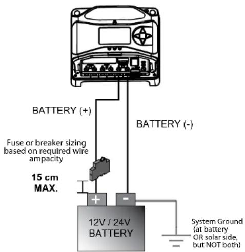
STEP 3: Grounding and Ground Fault Interruption

WARNING:
This unit is not provided with a GFDI device. This charge controller must be used with an external GFDI device as required by local regulations.

NOTE:
Depending on the country of installation, conductors identified by the color green, or a combination of green/yellow, shall only be used for earthing conductors.
Use the M4 screw on the left side of the heatsink to attach a grounding wire to the screw / heatsink, and connect the wire to the earth ground. Also tie any dead metal to earth ground.

WARNING: Risk of Fire
DO NOT bond the DC system electrical negative to the EcoBoost MPPT heatsink / earth ground. If local regulations require the use of a GFDI, the system negative must be bonded through the GFDI to earth ground at only one point.
Per IEC 62109, minimum sizes for equipment copper grounding wire are:
EcoBoost MPPT-20 10 mm
EcoBoost MPPT-30 10 mm
EcoBoost MPPT-40 10 mm
OR, of the same, or greater, cross-sectional area as the PV wires.
For safety, and effective lightning protection, it is recommended, and may be required by code, that the negative conductor of the charging system be properly grounded. Do not connect the negative conductor to the heatsink equipment grounding terminal.
STEP 4: Battery Connections - see diagram below
Be sure that DIP switches 2 and 3 are set for 12 or 24V as described in Section 3.2
NOTE: Before connecting the battery, measure the open-circuit voltage. It must be over 10 volts to start the controller. If the system voltage Settings Switches are set to Auto-detect, battery voltage over 15.5V will be detected as a 24V nominal battery, and the unit will charge accordingly. The 12/24V auto selection is only done at start-up.
With the battery disconnect open, connect the battery (+) and (-) wires from the battery to controller. DO NOT CLOSE THE BREAKER AT THIS TIME.
STEP 5: Solar Connections - see diagram below

WARNING: Shock Hazard
The solar PV array can produce open-circuit voltages in excess of 120 Vdc when in sunlight. Verify that the solar input breaker or disconnect has been opened (disconnected) before installing the system wires.
With the solar disconnect open, connect the solar (PV) array wires to the EcoBoost MPPT solar terminals. Use caution, since the solar array will produce current whenever in sunlight. A solar disconnect is a convenient way to break the PV connection when necessary. DO NOT CLOSE THE BREAKER AT THIS TIME.
STEP 6: Load Connections - see diagram below
CAUTION: Equipment Damage Do not wire any AC inverter to the load terminals of the EcoBoost MPPT. Damage to the load control circuit may result. An inverter should be wired to the battery. If there is a possibility that any other load will sometimes exceed the EcoBoost's maximum voltage or current limits, the device should be wired directly to the battery or battery bank. If load control is required, contact Morningstar Tech Support for assistance.
Turn the loads off, and connect the load wires to the load terminals. DO NOT CLOSE THE BREAKER AT THIS TIME.

STEP 7: Power-Up and Verify System Operation

NOTE: Carefully observe the LEDs after each connection. The LEDs will indicate proper polarity and a good connection.
Close the battery breaker to power on the controller. Watch the the charging status, and then the three battery state-of-charge (SOC) LEDs blink in sequence (G-Y-R), confirming proper start-up. If they do not light, check the battery polarity (+/-) and battery voltage.
Next, the green, yellow or red LED will light depending on the battery state-of-charge (SOC). Confirm that one of these LEDs is on before going to the next step.
Close the solar disconnect. If the solar input is connected while in sunlight, the charging LED indicator will light.
Confirm proper connection by observing the charging LED. Close the load disconnect, and turn the load on, to confirm a proper connection.
If the load does not turn on, it could be for various reasons:
- the EcoBoost MPPT is in LVD (red LED on)
- there is a short circuit in the load (LEDs blinking R/G - Y)
- there is an overload condition (LEDs blinking R/Y - G)
- the load is not connected, not working, or turned off
After all connections have been completed, observe the LEDs to make sure the controller is operating normally for system conditions. If the optional digital meter is used, observe that the display is scrolling with proper voltage and current values. Also, a self-test can be performed with digital meter units.
STEP 8: To Power-down
WARNING: Risk of Damage ONY disconnect the batter
ANY disconnect the battery from the EcoBoost MPPT AFTER the solar input has been disconnected. Damage to the controller may result if the battery is removed while the EcoBoost MPPT is charging.
- To prevent damage, power-down must be done in the reverse order as power-up.
4.0 OPERATION
4.1 TrakStar™ MPPT Technology
The EcoBoost MPPT utilizes Morningstar's TrakStar Maximum Power Point Tracking technology to extract maximum power from the solar module(s). The tracking algorithm is fully automatic and does not require user adjustment. TrakStar technology will track the array maximum power point voltage (Vmp) as it varies with weather conditions, ensuring that maximum power is harvested from the array through the course of the day.
High Voltage Strings and Grid-tie Modules
Another benefit of TrakStar MPPT technology is the ability to charge 12 or 24 Volt batteries with solar arrays of higher nominal voltages. A 12 Volt battery bank can be charged with a 12, 24, 36 or 48V nominal off-grid solar array. Certain grid-tie solar modules may also be used if the solar array open circuit voltage (V_oc) rating will not exceed the EcoBoost MPPT 120V maximum input voltage rating at worst-case (lowest) module temperature. The solar module documentation should provide V_oc vs. temperature data. Higher solar input voltage results in lower solar input current for a given input power. High voltage solar input strings allow for smaller gauge solar wiring. This is especially helpful for systems with long wiring runs between the solar array and the EcoBoost MPPT.
4.2 Battery Charging
4-Stage Charging
The EcoBoost MPPT has a 4-stage battery charging algorithm for rapid, efficient, and safe battery charging. Figure 4-1 shows the sequence of stages.
Figure 4-1. EcoBoost MPPT Charging Algorithm

WARNING: Risk of Explosion
Equalizing vented batteries produces explosive gases. The battery bank must be properly ventilated.

CAUTION: Equipment Damage
Equalization increases the battery voltage to levels that may damage sensitive DC loads. Verify all system loads are rated for the temperature compensated Equalize voltage before beginning an Equalization charge.

CAUTION: Equipment Damage
Excessive overcharging and gasing too vigorously can damage the battery plates and cause shedding of active material from the plates. An equalization that is too high or for too long can be damaging. Review the requirements for the particular battery being used in your system.
Battery Charge Settings
Preset EcoBoost MPPT battery charging options are shown in tables 4-1 and 4-2 below. All voltage settings listed are for nominal 12 Volt batteries. Multiply the voltage settings by two (2) for 24 Volt batteries.
NOTE: These settings are general guidelines for use at the operator's discretion. The EcoBoost MPPT can be programmed to satisfy a wide range of charging parameters. Consult the battery manufacturer for optimal battery charge settings.
| DBP Switch Settings 4.5&6 | Battery Type | Absorp. Stage (volts) | Fleet Stage (volts) | Equilator Stage (volts) | Absorp. Time (min) | Equilator Time (min) | Equilator Timeout (min) | Equilator Interval (days) | LVD (volts) | LVR (volts) |
| off-bi/f1 | - SaaSer* 14.00 | 3.50 | 150 | 11.50 | 12.60 | |||||
| off-bi/on | - Seeled* 14.15 | 3.50 14.00 | 150 60 | 120 28 | 11.30 | 12.80 | ||||
| off-or-off | - Seeled* | 14.30 | 13.50 | 14.60 | 150 | 60 | 120 | 28 | 11.50 | 13.00 |
| off-on-on | - AGM/Flooded | 14.70 | 13.50 | 15.10 | 180 | 170 | 180 | 28 | 11.90 | 13.70 |
| on off-bi | 5 Flooded | 14.50 | 13.50 | 15.30 | 180 | 120 | 160 | 28 | 11.90 | 13.40 |
| on-off-on | 6 Flooded | 14.70 | 13.50 | 15.40 | 180 | 180 | 240 | 28 | 12.10 | 13.60 |
| on-on-off | 7 - L16 | 13.40 | 13.40 | 16.00 | 180 | 180 | 240 | 14 | 12.30 | 13.80 |
| on on on | 8 Custom | Custom | Custom | Custom | Custom | Custom | Custom | Custom | Custom | Custom |
- "Sealed" battery type includes gel and AGM batteries
Table 4.1. Battery charging settings for each selectable battery type
Table 4.2. Battery settings that are shared among all battery types
| Absorption Extension Voltage | 12.50 | Volts |
| Absorption Extension Time | Absorption Time + 30 | minutes |
| Float Exit Time-out | 30 | minutes |
| Float Cancel Voltage | 12.30 | Volts |
| Equalize Time-out | Equalize Time + 60 | minutes |
| Temperature Compensation Co-efficient | - 30 | millivolts / °C / 12V |
4.3 Load Control Information
The primary purpose of the load control function is to disconnect system loads when the battery has discharged to a low state of charge, and to reconnect system loads when the battery is sufficiently recharged. System loads may be lights, DC appliances, or other electronic devices. The total current draw of all loads must not exceed maximum load ratings of 20 Amps (EB-20/M) or 30 Amps (EB-30/M or EB-40/M).
CAUTION: Equipment Damage Do not wire any AC inverter to the load terminals of the EcoBoost. Damage to the load control circuit may result. An inverter should be wired to the battery. If there is a possibility that any other load will sometimes exceed the EcoBoost MPPT's maximum voltage or current limits, the device should be wired directly to the battery or battery bank. If load control is required, contact Morningstar Tech Support for assistance.
Current Compensation:
All LVD and LVR set-points are current compensated. Under load, the battery voltage will sag in proportion to the current draw of the load. Without the current compensation feature, a short-term large load could cause a premature LVD. LVD and LVR set-points are adjusted lower per the following table:
Table 4-3. Current Compensation Values
| System Voltage | Current Compensation |
| 12 Volt -15 mV | per amp of load |
| 24 Volt -30 mV | per amp of load |
LVD Warning:
As the battery discharges, the Battery Status LEDs will transition from green to yellow and then from yellow to flashing red. The flashing red indication is a warning that a low voltage disconnect (LVD) event will occur soon.
The amount of time between a green SOC indication and load disconnect will depend on many factors including:
- rate of discharge (amount of load draw)
capacity of the battery - health of the battery
LVD set-point
If the battery discharges to the LVD set-point the load will disconnect and a solid red Battery Status LED indication will be displayed.
General Load Control Notes:
Do not wire multiple EcoBoost MPPT load outputs together in parallel to power DC loads with a current draw greater than 20 or 30A, depending on the EcoBoost MPPT model in use. Equal current sharing cannot be assured and an overload condition will likely occur on one or more controllers.
CAUTION: Equipment Damage Exercise caution when conne
specific polarity to a live load circuit. A reverse polarity connection may damage the load. Always double check load connections before applying power.
4.4 LED Indications
KEY:
G = green G - Y - R = flashing sequentially
Y = yellow G / Y = flashing together
R = red G / Y - R = G and Y flashing together, alternating with R flash
4.4.1. Power-up
Normal power-up: Status LED flashes G, then SOC LEDs flash G - Y - R, then SOC LEDs indicate battery charge status with a single battery status LED.
Failed bootload: Status LED flashes G, then SOC LEDs flash G - Y and stop on solid Y.
4.4.2 Status LED
The Status LED indicates charging status and any existing solar input error conditions. The Status LED is on when charging during the day and off at night. The Status LED will flash red whenever an error condition(s) exists. Table 4.4 lists the Status LED indications.
Table 4.4.Status LED Definitions
| Color Indication | Operating State | |
| None | Off (with heart-beat1) | Night |
| Green | On Solid ( with heart-beat2 ) | Charging |
| Red Flashing Error | ||
| Red | On Solid ( with heart-beat2 ) | Critical Error |
1 heartbeat indication flickers the Status LED on briefly every 5 seconds
2 heartbeat indication flickers the Status LED off briefly every 5 seconds
NOTES:
1) R flashing is generally a user addressable fault / error
2) R charging status LED ON with heartbeat blink OFF every 5 secs is a critical fault that generally requires service. See, "Solid Charging Status LED with Self-test (R-Y-G) SOC Faults", in Section 5.1.
4.4.3 State-of-Charge LEDs
Battery SOC LED Indications are shown in Table 4-5 below:
Table 4.5. Battery SOC LED Indications
| Condition Indication | |
| Absorption G flash - every sec | |
| Float | G flash - every 2 secs |
| Equalize | G flash - 2 / sec |
| SOC > 13.5V | G solid |
| 13.5V > SOC > 13.0V | G / Y solid |
| 13.0V > SOC > 12.5V | Y solid |
| SOC < 12.5V | Y / R solid |
| Low voltage disconnect warning | R flash - every sec |
| Low voltage disconnect | R solid |
4.5 Alarms
Solar Overload
No LED indication. The EcoBoost MPPT will limit battery current to the 20, 30 or 40 amp maximum rating. An oversized solar array will not operate at peak power. The solar array should be less than the EcoBoost MPPT nominal max. input power rating for optimal performance. See Section 7.0 - Technical Specifications for more information.
High Temperature Current Limit
The EcoBoost MPPT will limit the solar input current if the heatsink temperature exceeds safe limits. Solar charge current will be tapered back (to 0 amps if needed) to reduce the heatsink temperature. The EcoBoost MPPT is designed to operate at full rated current at the maximum ambient temperature. This alarm indicates that there is insufficient airflow and that the heatsink temperature is approaching unsafe limits. If the controller frequently reports this alarm condition, corrective action must be taken to provide better air flow or to re-locate the controller to a cooler spot.
High Input Voltage Current Limit
The EcoBoost MPPT will limit the solar input current as the solar array Voc approaches the maximum input voltage rating. The array Voc should never exceed the 120 volt maximum input voltage - see the array voltage de-rating graph in Appendix.
Current Limit
The array power exceeds the rating of the controller. This alarm indicates that the EcoBoost MPPT is limiting battery current to the maximum current rating.
RTS Open
The Remote Temperature Sensor is not connected to the controller. Use of the RTS is recommended for proper battery charging.
Heatsink Temperature Sensor Open / Shorted
The heatsink temperature sensor is damaged. Return the controller to an authorized Morningstar dealer for service.
Uncalibrated
The controller was not factory calibrated. Return the controller to an authorized Morningstar dealer for service.
4.6 Custom Settings
4.6.1 Adjusting Set-points with the Meter Display
The EcoBoost MPPT is available in metered and non-metered versions. The metered model allows:
- Custom programming directly from the unit.
- Extensive settings adjustment and information as shown partially in Figure 4-2 below.
Models:
EcoBoost-20M
EcoBoost-30M
EcoBoost-40M
Display Screens and Programming
Figure 4-2. Simplified Meter Map.
For metered models, see the included complete meter map insert, also available in the EcoBoost MPPT support documents at:
www.morningstarcorp.com
4.6.2 Meter Display Operation
4.6.2.1 Directional Key Use and Operation / Navigating the Meter Map
The EcoBoost MPPT's meter map consists of two main axes: The horizontal top level daily monitoring screens, and the vertical Main Menu stacked screens. The four lighted triangular directional control keys allow movement to reach any desired point on the meter map. A lit key indicates a valid direction in the map. The current location is indicated on the display with a column heading, and a bold descriptor.
4.6.2.2 Adjusting the Meter Display
The display setting options, as shown in Figure 4-2, are adjustable by using the directional keys to locate and edit a desired setting or variable.
4.7 Data Logging (future use)
The EcoBoost MPPT logs thirty days of basic system data:
- Daily minimum battery voltage
Daily maximum battery voltage - Daily Events (Equalize triggered, Entered Float, Alarm/ Fault occurred, Reset)
- Faults / Alarms - recorded only if a fault or alarm occurs that day
Daily charge to battery
The EcoBoost MPPT USB Micro-B port (for future use) will allow data transfer in mobile applications.
4.8 Auxiliary USB Charging
1) The EcoBoost MPPT has two USB-A ports for use as charging sources for small electronics. Energy is taken from the system battery, so any auxiliary charging must be balanced with other load draws on the system battery.
2) The USB charging ports will operate in all conditions except for LVD, HVD, or a user requested Load Disconnect (from a meter command, for example). In LVD, HVD & Load Disconnect, the main load and the USB ports are powered off.
3) If the main load gets faulted for some reason (shorted FET, etc), the USB charging ports will still operate.
4.9 Inspection and Maintenance
Table 4-6 below lists the recommended maintenance schedule to keep your EcoBoost MPPT performing optimally.
WARNING: RISK OF ELECTRICAL SHOCK. NO POWER OR ACCESSORY TERMINALS ARE ELECTRICALLY ISOLATED FROM DC INPUT, AND MAY BE ENERGIZED WITH HAZARDOUS SOLAR VOLTAGE. UNDER CERTAIN FAULT CONDITIONS, BATTERY COULD BECOME OVERCHARGED. TEST BETWEEN ALL TERMINALS AND GROUND BEFORE TOUCHING.
WARNING: SHOCK HAZARD DISCONNECT ALL POWER SOURCES TO THE CONTROLLER BEFORE REMOivating THE WIRING BOX COVER. NEVER REMOVE THE COVER WHEN VOLTAGE EXISTS ON THE ECOBOOST MPPT POWER CONNECTIONS.
| Schedule Maintenance Items | |
| 2 weeks after installation | Re-tighten power terminal connections to specified torque values. |
| 3 months after installation | Re-tighten power terminal connections to specified torque values. |
| Monthly or After Each Equalization | Inspect the battery bank. Look for cracked or bulging cases, and corroded terminals. For wet cell (flooded type) batteries, make sure the water level is correct. Wet cell water levels should be checked monthly or according to the manufacturer's recommendations. |
| Annually | Clean the heatsink fins with a clean, dry rag. Inspect all wiring for damage or fraying. Inspect for nesting insects. Re-tighten all wiring terminal connections to specified torque values. Inspect the system earth grounding for all components. Verify all grounding conductors are appropriately secured to earth ground. |
Table 4-6. Maintenance Schedule
5.0 TROUBLESHOOTING
WARNING: RISK OF ELECTRICAL SHOCK. NO POWER OR ACCESSORY TERMINALS ARE ELECTRICALLY ISOLATED FROM DC INPUT, AND MAY BE ENERGIZED WITH HAZARDOUS SOLAR VOLTAGE. UNDER CERTAIN FAULT CONDITIONS, BATTERY COULD BECOME OVERCHARGED. TEST BETWEEN ALL TERMINALS AND GROUND BEFORE TOUCHING.
WARNING: SHOCK HAZARD A MEANS OF DISCONNECTING ALL POWER SUPPLY POLES MUST BE PROVIDED. THESE DISCONNECTS MUST BE INCORPORATED IN THE FIXED WIRING. OPEN ALL POWER SOURCE DISCONNECTS BEFORE REMOVIDING CONTROLLER WIRING COVER, OR ACCESSING WIRING.
5.1 LED Fault Indications
Load Over-current
Error Status LED: Flashing red. Battery status LEDs: R/Y-G sequencing. If the load current exceeds the maximum load current rating, the EcoBoost MPPT will disconnect the load. The greater the overload the faster the load will be disconnected. A small overload could take a few minutes to disconnect. The EcoBoost MPPT will attempt to reconnect the load two (2) times. Each attempt is approximately 10 seconds apart. If the overload remains after two (2) attempts, the load will remain disconnected until power is removed and re-applied.
Solar Short Circuit
Charging Status LED: OFF. Solar input power wires are short-circuited. Charging automatically resumes when the short is cleared.
Battery Reverse Polarity
No LED indication, the unit is not powered. No damage to the controller will result. Correct the miswire to resume normal operation.
Load Short Circuit
Error status LED: Flashing red. Battery status LEDs: R/G-Y sequencing. Fully protected against load wiring short-circuits. After two (2) automatic load reconnect attempts (10 seconds between each attempt) the EcoBoost MPPT will wait, and then automatically reconnect the load, once the short is cleared.
High Solar Voltage Disconnect
Charging Status LED: R flashing. No battery status errors. If the solar input open-circuit voltage (Voc) exceeds the 120 volt maximum rating, the array will remain disconnected until the Voc falls safely below the maximum rating.
Remote Temperature Sensor (RTS)
Error status LED: Flashing red. Battery status LEDs: R/Y - G/Y sequencing. A bad RTS connection or a severed RTS wire has disconnected the temperature sensor during charging. Charging automatically resumes when the problem is fixed. To resume operation without an RTS, disconnect all power to the EcoBoost MPPT and then reconnect. If the controller is re-started with the failure still present, the controller may not detect that the RTS is connected, and the LEDs will not indicate a fault. A metered model, an RM-1 meter, or MSView PC software can be used to determine if the RTS is working properly.
Battery / Load High Voltage Disconnect (HVD)
Error status LED: Flashing red. Battery status LEDs: R-G sequencing. This fault is set when battery voltage is above normal operating limits. The controller will disconnect the solar input and set a High Voltage Disconnect fault. This fault is commonly caused by other charging sources in the system, charging the battery above the EcoBoost MPPT regulation voltage. Recovery occurs at HVD re-connect threshold, and the fault will automatically clear. See Section 7 - Technical Specifications for values.
High Heatsink Temperature
Error status LED: Flashing red. Battery status LEDs: R-Y sequencing. The heatsink temperature has exceeded safe limits and the load is disconnected. The load will automatically reconnect when the heatsink cools to a safe temperature.
Battery Over-current
Error status LED: Flashing red. Battery status LEDs: R/Y-G sequencing. While rare, if battery current exceeds approximately 130% of the controller's output current rating, this fault can occur. The fault is generally related to fast, large battery voltage transients (connecting a very heavy or capacitive load like an inverter) that are faster than the controller can regulate, and it shuts off to protect the circuitry. The controller will automatically re-start in 10 seconds.
Settings (DIP) Switch Changed
Error status LED: Flashing red. Battery status LEDs: R-Y-G sequencing. If a settings switch is changed while there is power to the controller, the LEDs will begin sequencing and the solar input will disconnect. The controller must be re-started to clear the fault and begin operation with the new settings.
Custom Settings Edit
Error status LED: Flashing red. Battery status LEDs: R-Y-G sequencing. A value has been modified in custom settings memory. The controller will stop charging and indicate a fault condition. After all settings have been modified, the controller must be reset by removing and then restoring power to the controller. The new programmed settings will be used after the power reset.
Firmware Update Failure
The firmware update was not successfully programmed. The controller will not indicate the full power-up LED sequence of G-Y-R when power to the controller is reset. Instead, the controller will display green, and then stop on yellow. The yellow LED will continue to be lit and the controller will not complete start up or begin charging.
Re-try the firmware update. The firmware must be successfully loaded before the controller will start up.
SOLID CHARGING STATUS LED with SELF-TEST (R-Y-G) SOC FAULTS
Verify that nothing has been mis-wired. If not, the error is likely critical. Contact an authorized Morningstar dealer for support.
| Fault Charging Status LED Battery SOC LEDs | ||
| PV FET Short Solid | red R-Y-G sequencing | |
| Load FET Short Solid | red R-Y-G sequencing | |
| Load FET Open Solid | red R-Y-G sequencing | |
| Damaged local temperature sensor | Solid red (only if RTS is invalid) | R-Y-G sequencing |
| Damaged heatsink temperature sensor | Solid red R-Y-G | sequencing |
| Software Solid | red R-Y-G sequencing | |
RE-SETTABLE SELF-TEST (R-Y-G) SOC FAULTS
| Fault - Battery | SOC LEDs | |
| Custom Settings Edit | R-Y-G sequencing | |
| DIP Switch Change | R-Y-G sequencing |
5.2 Battery Charging and Performance Issues
Problem:
No LED indications, controller does not appear to be powered
Solution:
With a multi-meter, check the voltage at the battery terminals on the EcoBoost MPPT. Battery voltage must be 10 vdc or greater. If the voltage on the battery terminals of the controller is between 10 and 35 vdc, and no LEDs are lit, contact your authorized Morningstar dealer for service. If no voltage is measured, check wiring connections, fuses, and breakers.
Problem:
The EcoBoost MPPT is not charging the battery.
Solution:
Check the three (3) battery SOC LEDs. If they are flashing in a sequence, see Section 4.5 LED indications of this manual to determine the cause. A metered model, an RM-1 meter, or MSView PC software will display active faults and alarms.
If the LED indications are normal, check the fuses, breakers, and wiring connections in the power source wiring. With a multi-meter, check the array voltage directly at the EcoBoost MPPT solar input terminals. Input voltage must be greater than battery voltage before charging will begin.
Problem:
Controller makes buzzing and humming noises.
Solution:
No action is required. This is expected due to magnetic resonance and circuit switching.
If troubleshooting does not correct the problem, please refer to Morningstar's Warranty Claim Procedure in Section 6.
6.0 WARRANTY
LIMITED WARRANTY Morningstar Solar Controllers and Inverters
The EcoBoost MPPT is warranted to be free from defects in material and workmanship for a period of TWO (2) years from the date of shipment to the original end user. Morningstar will, at its option, repair or replace any such defective products.
WARRANTY EXCLUSIONS AND LIMITATIONS:
This warranty does not apply under the following conditions:
Damage by accident, negligence, abuse or improper use
PV or load currents exceeding the ratings of the product
Unauthorized product modification or attempted repair
Damage occurring during shipment
Damage results from acts of nature such as lightning and weather extremes
THE WARRANTY AND REMEDIES SET FORTH ABOVE ARE EXCLUSIVE AND IN LIEU OF ALL OTHERS, EXPRESS OR IMPLIED. MORNINGSTAR SPECIFICALLY DISCLAIMS ANY AND ALL IMPLIED WARRANTYES, INCLUDING, WITHOUT LIMITATION, WARRANTYES OF MERCHANTABILITY AND FITNESS FOR A PARTICULAR PURPOSE. NO MORNINGSTAR DISTRIBUTOR, AGENT OR EMPLOYEE IS AUTHORIZED TO MAKE ANY MODIFICATION OR EXTENSION TO THIS WARRANTY.
MORNINGSTAR IS NOT RESPONSIBLE FOR INCIDENTAL OR CONSEQUENTIAL DAMAGES OF ANY KIND, INCLUDING BUT NOT LIMITED TO LOST PROFITS, DOWN-TIME, GOODWILL OR DAMAGE TO EQUIPMENT OR PROPERTY.
R15-8/15
CHNICAL SPECIFICATIONS
EB-MPPT-20/M EB-MPPT-30/M EB-MPPT-40/M
Electrical:
Nominal Battery Voltage 12 volts or 24 volts (all)
Battery Voltage Range 10-35 volts (all)
Voltage Accuracy 0.1% +/- 50mV (all)
Max. Battery Current
20Amps 30Amps 40Amps
Max. PV Open-Circuit Voltage
All: 120 Volts
Load Current Rating
20 Amps 30 Amps 30 Amps
Self Consumption
<25mA (no meter) <40mA (meter)
LED Indications
(1) status, (3) battery SOC
Transient Surge Protection
4500 watts (solar, battery, load)
Conversion Efficiency (peak)
97.3% (all)
Mechanical:
Dimensions (cm) 19.6(W) x 18.1(L) x 7.1(D)
Weight (kg) 1.4
Wire Size Range:
Power Terminals
2.5-16mm /#14-2AWG
(maximum torque)
3.95 Nm
Temp. Sense
0.25 - 1.0 mm /#24-16AWG
Enclosure IP20,Type 1
Battery Charging:
4-Stage Charging: Bulk, Absorption, Float, Equalize
Temperature compensation
Coefficient: -30mV / 12 volt / °C
Temperature compensated
set-points: Absorption, Float, Equalize, HVD
and HVDR (solar)
Battery Charging Set-points (@ 25^) [multiply voltages by (2) for 24 volt systems]
| DIP Switch Settings 4-5-6 | Battery Type | Absorp. Stage (volts) | Frost Stage (volts) | Equilator Stage (volts) | Absorp. Time (min) | Equilator Time (min) | Equilator Tolerance (min) | Equilator Interval (days) | IVD (volts) | IVR (volts) |
| off-off-off | 1 - Sealed* | 14.00 | 13.50 | 150 | 11.50 | 12.60 | ||||
| off-off-on | 2 - Scaled* | 14.15 | 13.50 | 14.40 | 150 | 60 | 120 | 28 | 11.30 | 12.60 |
| off-on-off | 3 - Scaled* | 14.30 | 13.50 | 14.60 | 150 | 60 | 120 | 28 | 11.50 | 13.00 |
| off-on-on | 4 - AGM/Hooded | 14.40 | 13.50 | 15.10 | 180 | 120 | 180 | 28 | 11.70 | 13.20 |
| on-off-off | 5 - Flooded | 14.60 | 13.50 | 15.30 | 180 | 170 | 180 | 28 | 11.90 | 13.40 |
| on-off-on | 6 - Flooded | 14.70 | 12.50 | 15.40 | 180 | 180 | 240 | 28 | 12.10 | 60 |
| on-on-on | 7 - I-16 | 15.40 | 13.40 | 16.00 | 180 | 180 | 240 | 14 | 12.30 | 13.60 |
| on on on | 8 - Custom | Custom | Custom | Custom | Custom | Custom | Custom | Custom | Custom | Custom |
- "Sealed" battery type includes gel and AGM batteries
Current Compensation:
12 Volt systems -15 mV/A
24 Volt systems -30 mV/A
Compensated set-points LVD
Compensation threshold 3A
Load and Solar Control (multiply voltages by (2) for 24 volt systems):
Default values (customizable) LVD/USB charging See table above
LVR See table above
Instant LVD 10.0V
HVD - solar Current stage set-point + 0.5V (@25°C)
HVD - load / USB charging 15.3V
HVDR - solar 13.8V (@ 25°C)
HVDR - load USB charging 14.5V
LVD Warning 10 minutes
LVD Override 10 minutes
Maximum # LVD overrides No limit unless (not customizable) V_batt < Instant LVD
Lighting Control (DIP 1 ON):
Lighting Timer Setting Dusk-Dawn (default) Lighting Test Timer 5 minutes
Data & Communications:
Data Port (future use) USB Micro-B
Datalogging (future use) 30-day maximum
Comm. Protocol Serial
Digital Meter:
Resolution 128 x 64
Viewing Area 70mm x 40mm
Display Color blue on white
Backlight LED
Operating Temperature -20°C to +60°C
Storage Temperature -30°C to +80°C
Environmental:
Maximum Operating Altitude 2000 meters
Operating Temperature -40°C to +60°C
Storage Temperature -40°C to +80°C
Humidity 100% n.c.
Tropicalization Conformally coated PCBs, Marine-rated terminals
Protections
Power-up against any active faults
Reverse Polarity - battery and array
Solar Short-Circuit
Solar High Voltage Disconnect
High Heatsink Temperature - Current De-rating
High Heatsink Temperature - Load Disconnect
Load Short-Circuit
Load Over-Current
Heatsink Temperature Limit
RTS Terminals
8.0 CERTIFICATIONS

IEC 62109-1 EN 62109-1
www.tuv.com ID 6007000000


Complies with CSA-C22.2 No. 107.1
IEC 62109-1
FCC Class B compliant
ENs Directives:
- Complies with ENs and LVD standards for CE marking
EN 62109-1
Emissions 55014-1
Immunity 55014-2
EcoBoost MPPT™ is a trademark of Morningstar Corporation
©2018 Morningstar Corporation. All rights reserved.
EcoBoost MPPT™
World's Leading Solar Controllers & Inverters
www.morningstarcorp.com
MS-002243
v2.3

MODELS
EB-MPPT-20 EB-MPPT-20M
EB-MPPT-30 EB-MPPT-30M
EB-MPPT-40 EB-MPPT-40M
INTION: RISQUE D'ÉLECTROCUTION
DEBRANCHEZ TOUTES LES SOURCES D'ALIMENTATION DU REGULATEUR AVANT DE RETIRER LE Cache DU BOITIER DE RACCORDEMENT. NE RETIREZ JAMAIS LE CACHE LORSQUE LES BRANCHEMENTS ELECTRIQUES DE L'ECOBOOST MPPT SONT SOUS TENSION.
EB-MPPT-20/M EB-MPPT-30/M EB-MPPT-40/M
HVDR-PV 13,8V (a 25^
HVDR - charge 14,5 V
Avertissement LVD 10 minutes

Registration, Evaluation and Authorization of Chemicals

EB-MPPT-20M EB-MPPT-30M EB-MPPT-40M
Elektrisch:
Registration, Evaluation and Authorization of Chemicals

EB-MPPT-20/M EB-MPPT-30/M EB-MPPT-40/M
Aspectos electrolycos:
Voltaje de bateria nominal 12 voltios o 24 voltios (todos)
Registration, Evaluation and Authorization of Chemicals