
ES 3160 - Audio Amplifier RCF - Free user manual and instructions
Find the device manual for free ES 3160 RCF in PDF.
| Product type | Audio mixer/amplifier with MP3 CD/USB player and radio tuner |
| Brand | RCF |
| Model | ES 3160 |
| Output power | 160 W RMS |
| Audio inputs | 4 balanced mic/line on removable connectors (input 1 also XLR) |
| Auxiliary input | AUX INPUT on RCA connectors |
| Speaker outputs | Constant voltage 100 V / 70 V or low impedance 4 Ω |
| Preamp outputs | PRE OUT, MUSIC ON HOLD, INTERNAL PROGRAM (RCA) |
| MP3 CD/USB player | Audio CD, CD-R, CD-RW, USB flash drive (MP3 files) |
| Radio tuner | FM/AM with RDS, 18 FM presets, 12 MW |
| Power supply | 115-230 V, 50/60 Hz, internal switchable |
| Dimensions (W x H x D) | 444 x 127 x 345 mm |
| Net weight | 8 kg |
| Power consumption | 350 W |
| Frequency response (amplifier) | 50 Hz - 13.5 kHz |
| Signal-to-noise ratio | Mic: 60 dB, Aux: 80 dB |
| Harmonic distortion | < 0.3% at 1 kHz (rated power) |
| Priority functions | VOX input 1, graduated or interlocked priorities, CHIME/SIREN |
| Announcement microphone compatibility | RCF BM 3001 via RJ45 ports (channels 2 and 3) |
| Protections | Short circuit, thermal, mains fuses |
| Maintenance and cleaning | Soft dry cloth; do not use solvent, alcohol or benzene |
| Safety | Class I, mandatory grounding; do not open; avoid moisture and splashes |
| Spare parts and repairability | Contact RCF customer service or an approved center for any repair |
Frequently Asked Questions - ES 3160 RCF
User questions about ES 3160 RCF
0 question about this device. Answer the ones you know or ask your own.
Ask a new question about this device
Download the instructions for your Audio Amplifier in PDF format for free! Find your manual ES 3160 - RCF and take your electronic device back in hand. On this page are published all the documents necessary for the use of your device. ES 3160 by RCF.
USER MANUAL ES 3160 RCF
Pulsante TOP (solo CD audio e file MP3)
Pulsante Folder- (solo file MP3)
Pulsante Folder+ (solo file MP3)
EON "enhanced other networks"
USCITA BASSA IMPEDENZA (4Ω)
Bass ±8dB@80Hz
- Treble ± 8 dB @ 13 kHz
Controllo PRESENCE (ingressi 1 ÷ 4) + 10 dB @ 2.15 kHz
Filtro passa-alto (ingressi 1÷ 4 150 Hz
SENSIBILITA D'INGRESSO / IMPEDENZA
MIC (1÷4) Bilanciato 50 dBu /10 kO
MIC PHANTOM (1÷4) Bilanciato -21 dBU / 5 kΩ
LINE (1÷ 4) Bilanciato 0 dBu (max. +16 dBu)/10 kΩ
AUX INPUT Regolabile -6÷ +13 dBu/20kΩ
LIVELLO D'USCITA / IMPEDENZA
AUX OUTPUT (pre / music on hold)
Tensione / corrente "Phantom power" - 1 dBu/600Ω
32 V/18 mA
USCITE DIFFUSORI (POTENZA: 160 W)
Bassa impedenza
Tensione costante 4Ω(25V)
RADIO
SAFETY PRECAUTIONS page 27
DESCRIPTION page 29
FRONT PANEL page 29
REAR PANEL page 31
OPERATION page 34
CD/USB-MP3PLAYERANDTUNERpage36
- FRONT PANEL page 37
FUNCTION MENU page 41
NOTES ABOUT MP3 FILES page 42 - MP3 FILE SEARCH page 42
- REMOTE CONTROL page 43
- ERROR CODES page 44
LOUDSPEAKER CONNECTION page 44
POWER SUPPLY VOLTAGE CHANGE page 45
SPECIFICATIONS page 46
EXAMPLE OF CONNECTIONS page 47
Before connecting and using this product, please read this instruction manual carefully and keep it on hand for future reference. The manual is to be considered an integral part of this product and must accompany it when it changes ownership as a reference for correct installation and use as well as for the safety precautions.
RCF S.p.A. will not assume any responsibility for the incorrect installation and / or use of this product.
WARNING: To prevent the risk of fire or electric shock, never expose this product to rain or humidity.

SAFETY PRECAUTIONS
- All the precautions, in particular the safety ones, must be read with special attention, as they provide important information.
2. POWER SUPPLY FROM MAINS
a. The mains voltage is sufficiently high to involve a risk of electrocution; therefore, never install or connect this product with the power supply switched on.
b. Before powering up, make sure that all the connections have been made correctly and the voltage of your mains corresponds to the voltage shown on the rating plate on the unit, if not, please contact your RCF dealer.
c. The metallic parts of the unit are earthed by means of the power cable. An apparatus with CLASS I construction shall be connected to a mains socket outlet with a protective earthing connection.
d. Protect the power cable from damage; make sure it is positioned in a way that it cannot be stepped on or crushed by objects.
e. To prevent the risk of electric shock, never open the product: there are no parts inside that the user needs to access.
-
Make sure that no objects or liquids can get into this product, as this may cause a short circuit. This apparatus shall not be exposed to dripping or splashing. No objects filled with liquid, such as vases, shall be placed on this apparatus. No naked sources (such as lighted candles) should be placed on this apparatus.
-
Never attempt to carry out any operations, modifications or repairs that are not expressly described in this manual. Contact your authorized service centre or qualified personnel should any of the following occur:
-
The product does not function (or functions in an anomalous way).
- The power supply cable has been damaged.
-
Objects or liquids have got into the unit.
The product has been subject to a heavy impact. -
If this product is not used for a long period, disconnect the power cable.
- If this product begins emitting any strange odours or smoke, switch it off immediately and disconnect the power supply cable.
- The terminals marked with the symbol are HAZARDOUS LIVE and their connection is to be made by an INSTRUCTED PERSON or the use of ready-made cables is required.
- Do not connect this product to any equipment or accessories not foreseen. For suspended installation, only use the dedicated anchoring points and do not try to hang this product by using elements that are unsuitable or not specific for this purpose. Also check the suitability of the support surface to which the product is anchored (wall, ceiling,

structure, etc.), and the components used for attachment (screw anchors, screws, brackets not supplied by RCF etc.), which must guarantee the security of the system / installation over time, also considering, for example, the mechanical vibrations normally generated by transducers. To prevent the risk of falling equipment, do not stack multiple units of this product unless this possibility is specified in the user manual.
- RCF S.p.A. strongly recommends this product is only installed by professional qualified installers (or specialised firms) who can ensure correct installation and certify it according to the regulations in force.
The entire audio system must comply with the current standards and regulations regarding electrical systems.
10. SUPPORTS AND TROLLEYS
The equipment should be only used on trolleys or supports, where necessary, that are recommended by the manufacturer. The equipment / support / trolley assembly must be moved with extreme caution. Sudden stops, excessive pushing force and uneven floors may cause the assembly to overturn.
- There are numerous mechanical and electrical factors to be considered when installing a professional audio system (in addition to those which are strictly acoustic, such as sound pressure, angles of coverage, frequency response, etc.).
12. HEARING LOSS
Exposure to high sound levels can cause permanent hearing loss. The acoustic pressure level that leads to hearing loss is different from person to person and depends on the duration of exposure. To prevent potentially dangerous exposure to high levels of acoustic pressure, anyone who is exposed to these levels should use adequate protection devices. When a transducer capable of producing high sound levels is being used, it is therefore necessary to wear ear plugs or protective earphones.
See the technical specifications in loudspeaker instruction manuals to know their maximum sound pressure levels.
IMPORTANT NOTES
To prevent the occurrence of noise on microphone / line signal cables, use screened cables only and avoid putting them close to:
- Equipment that produces high-intensity electromagnetic fields (for example, high power transformers)
- Mains cables
- Loudspeaker lines.
OPERATING PRECAUTIONS
- Do not obstruct the ventilation grilles of the unit. Situate this product far from any heat sources and always ensure adequate air circulation around the ventilation grilles.
- Do not overload this product for a long time.
- Never force the control elements (keys, knobs, etc.).
- Do not use solvents, alcohol, benzene or other volatile substances for cleaning the external parts of this product.
RCF S.p.A. thanks you for purchasing this product, which has been designed to guarantee reliability and high performances.
DESCRIPTION
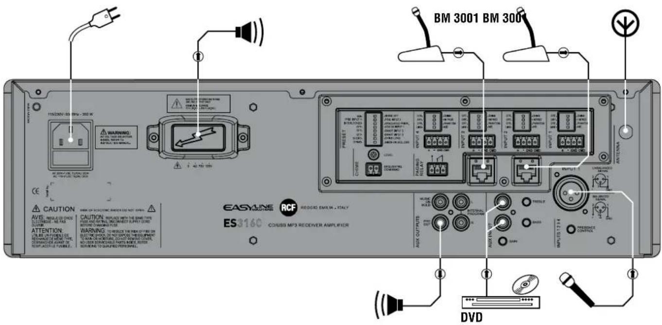
ES 3160 is a mixer-amplifier with 4 mic-line audio inputs on removable connectors (the first input also has an XLR socket), CD/USB - MP3 player and tuner and an aux input for an additional external music source.
The amplifier nominal power is 160 W, available on either a low impedance output (min. 4 Ω) or 100 - 70 V constant voltage output (for loudspeakers having 100 - 70 V transformers).
Input 1 has a signal detection circuit ('VOX') providing automatic priority operation. All inputs 1, 2, 3 and 4 can access the priority through an external command (connected to the removable connector). Inputs 2 and 3 also have an RJ 45 socket for quick connection of an RCF BM 3001 paging microphone (through CAT5 cable).
A USB port (on the front panel) allows connection of a USB flash drive containing MP3 files.
Aux outputs are available to send the internal / external music source signals to additional amplifiers, mixers, phone systems ('music on hold' function), etc..
The 4 mic.-line inputs have a common 'presence' control and separate high-pass filters that are useful for improving speech intelligibility. Both the internal music source (CD/USB - MP3 player and tuner) and the AUX INPUT have separate tone controls.
Front panel LED's indicate the device state (ON, PROT), the priority activation (PRIOR) and the signal level (SIG/PK).
FRONT PANEL
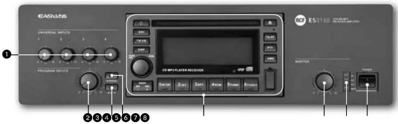
Volume controls for each universal input (1, 2, 3, 4) Note: unused channels should always be turned counterclockwise (to 0).
AUX INPUT volume control Note: turn counterclockwise (to 0) if the aux input is not used.
AUX IN button (with LED)
It turns on (LED is lit) / off the AUX INPUT to the internal amplifier (and PRE OUT).
If activated, the CD/USB - MP3 player / tuner signal will not be sent to the internal amplifier (the INTERNAL button LED will turn off).
The AUX INPUT signal is always sent to the MUSIC ON HOLD output (that is not affected by the AUX IN button).
INTERNAL button (with LED)
It turns on (LED is lit) / off the CD/USB - MP3 player / tuner to the internal amplifier (and PRE OUT).
If activated, the AUX INPUT signal will not be sent to the internal amplifier (the AUX IN button LED will turn off).
The CD/USB MP3 player / tuner signal is always sent to the INTERNAL PROGRAM output (that is not affected by the INTERNAL button).
It takes 10 seconds (after pressing either the AUX IN or INTERNAL button) to store on its memory the last selection.
CD/USB - MP3 player and tuner (read the relevant manual section at page 36).
Internal amplifier MASTER volume control
Note: all audio outputs via RCA connectors (INTERNAL PROGRAM, MUSIC ON HOLD, PRE OUT) are not affected by the MASTER volume control.
7 LEDs
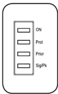
ON green: the device is switched on
PROT red: overload protection orange: thermal protection
PRIORITY yellow: priority by either the VOX function or an universal input or the SEQ.COMMAND.
SIG/PK green: the signal level is higher than -15 dB green + red: the signal level is in the 0÷ +2 dB range red: the signal level is equal or higher than +3 dB
1 0dB = signal level that allows to get the amplifier maximum power.
The internal 'limiter' circuit helps to avoid the amplifier overloading, yet it is advisable to reduce the MASTER volume (or a single channel volume where a 'too high' signal is present) when the SIG/PK LED is continuously indicating red.
Main POWER switch (0 = off; 1 = on)
REAR PANEL
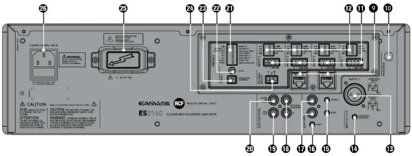
2 RJ 45 sockets (channels 2 and 3) to connect 1 RCF BM 3001 paging microphone per socket.
Note: when a BM 3001 paging microphone is connected, it is necessary to set the dip-switches 3 and 4 to MIC. PHANTOM (see 12 below) of the relevant channel.
10 Antenna input (the antenna is necessary when using the tuner).
14 balanced audio inputs (channels 1, 2, 3, 4) with sockets for removable connectors.
| + Hot audio input |
| - Cold audio input |
| GND ground |
| CMD command - priority access when connected to ground |
12 Each channel has 4 dip-switches:
| 1 | OFF- CHIME OFF: | the chime is disabled. | CHIME: the chime will be played as soon as a priority command is activated. |
| 2 | OFF- HI PASS | OFF: the audio hi-pass filter is not inserted (flat frequency response). | HI PASS: the audio hi-pass filter is inserted. |
| 3 | OFF- PHANTOM | OFF: the PHANTOM power supply is not available on the relevant audio input. | PHANTOM: the PHANTOM power supply is available on the relevant audio input. |
| 4 | LINE- MIC LINE: line audio input. MIC: microphone audio input. | ||
Examples of dip-switches 3 and 4 settings:
| DIP 3 DIP 4 | MODE | USE (EXAM) | PLES) |
| OFF | LINE | LINE | CD/MP3 players, tuners, message players, phone systems |
| OFF | MIC | MIC | Dynamic microphones |
| PHANTOM | MIC | MIC with PHANTOM BM | 3001 paging microphones, electret microphones |
When a BM 3001 paging microphone is used, it is necessary to choose the 'MIC with PHANTOM' mode in the relevant channel (dip-switch no.3 set to PHANTOM; dip-switch no.4 set to MIC).

Channel no.1 XLR input
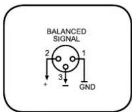
BALANCED CONNECTION
+
hot
一
cold
GND
ground

UNBALANCED CONNECTION
14 PRESENCE CONTROL (f = 2.15kHz) common for all the channels 1, 2, 3, 4.
15 AUX INPUT TREBLE and BASS controls.
16 AUX INPUT GAIN control.
17 AUX INPUT with dual RCA connector.
The two channels of the stereo source connected to the AUX INPUT are summed internally (to get a mono signal).
16 INTERNAL PROGRAM stereo audio output with dual RCA connector (L: left channel, R: right channel) that sends the direct CD/USB - MP3 player and tuner signal.
PRE OUT audio output (with RCA connector) that sends the same signal routed to the internal amplifier (signal that can be either a single source with priority or the mix of all the channels 1, 2, 3, 4 and the selected music source).
Use PRE OUT for connection of additional external amplifiers.
20 MUSIC ON HOLD audio output (with RCA connector) that sends a mono signal of the source connected to the AUX INPUT.
Either the MUSIC ON HOLD output (if an external music source has been connected to the AUX INPUT) or the INTERNAL PROGRAM output can be used for the connection to a telephone system (in order to have the 'music on hold' function).
21 8 dip-switches PRESET to set the priority options:
| 1. | MIX-MUSIC OFF | MIX: the music source (internal or external) is always present in the (mixed) signal sent to the amplifier, even during a priority command. | MUSIC OFF: the music source (internal or external) is not sent to the amplifier during a priority command. |
| 2. | PRIO INPUT 1 PRIO INPUT 2 | PRIO INPUT 1: the channel 1 has the highest priority level with override (but the CHIME SEQUENTIAL COMMAND) through the relevant command (or VOX), if the dip-switch no.3 has been set to 'graduated priority'. | PRIO INPUT 2: the channel 2 has the highest priority level with override (but the CHIME SEQUENTIAL COMMAND) through the relevant command, if the dip-switch no.3 has been set to 'graduated priority'. |
| 3. | INTERLOCKED GRADUATED PRIOR. | INTERLOCKED: interlocked priority mode (read the 'Operation' section). | GRADUATED PRIOR.: graduated priority mode (read the 'Operation' section). |
| 4. | OFF VOX ON INPUT 1 | OFF: the channel 1 VOX function is off. | VOX ON INPUT 1: the channel 1 VOX function is on (automatic priority when a signal is detected on the audio INPUT 1). |
| 5. | OFF SMART INPUT 2 | OFF: the channel 2 priority is kept only if the relevant command is still present ('push' mode). | SMART INPUT 2: the channel 2 priority is switched on / off by every impulse of the relevant command ('toggle' mode). |
| 6. | OFF SMART INPUT 3 | OFF: the channel 3 priority is kept only if the relevant command is still present ('push' mode). | SMART INPUT 3: the channel 3 priority is switched on / off by every impulse of the relevant command ('toggle' mode). |
| 7. | SHORT CHIME LONG | SHORT: short chime. CHIME LONG: long chime. | |
| 8. | CHIME SIREN ON SEQ. CMD | CHIME: the chime (selected by the dip-switch no.7) is continuously played when the 'CHIME SEQUENTIAL COMMAND' is activated. | SIREN ON SEQ.CMD: an alarm tone is sent when the 'CHIME SEQUENTIAL COMMAND' is activated. |
CHIME LEVEL (a trimmer adjustable by using a small screwdriver).
23 CHIME SEQUENTIAL COMMAND with removable connector (activated when the 2 pins are short-circuited) to send either the chime continuously (the chime type can be selected by the dip-switch no.7, see 21-7) or an alarm tone.
If the dip-switch no.8 is set to "SIREN ON SEQ.CMD", the alarm tone will have the maximum volume level (adjustable by the MASTER volume only).
24 Internal relay contacts (3 pole removable connector). The internal relays switches when a priority command is present.
- normally open
- common
- normally closed
Max. voltage: 24 V; max. current: 0.5 A
25 Amplifier output (max. 160 W) to loudspeakers (100/70 V constant voltage line -4Ω impedance). Use ONE output only (read the section 'Loudspeaker connection').
26 Mains connector with fuse Before connecting the power supply cable, verify that the apparatus voltage (230 or 115 V ac) corresponds to the available mains supply. Note: the fuse type is marked on the rear panel (below the mains connector).
OPERATION
1 'VOX' is an internal circuit that automatically activates the channel 1 priority when a signal is detected on the audio INPUT 1.
POWER ON (OR WHEN A PRIORITY COMMAND ENDS)
If no priority command is present (including VOX and CHIME SEQUENTIAL COMMAND), all the channels 1, 2, 3, 4 and the music source are mixed together.
The music source can be:
The internal CD/USB - MP3 player and tuner.
The AUX INPUT signal.
- Disabled.
The music volume depends on either the CD/USB - MP3 player / tuner VOL control (if selected) or the AUX IN volume control on the front panel (see 2). AUX INPUT level also depends on the relevant GAIN control setting (see 16) on the rear panel.
The music source (internal or external) can be activated / muted through the front panel buttons (see 3 and 4).
PRIORITY
If a priority command is present (or VOX), the music source can be either included in the mixed signal sent to the amplifier or excluded, according to dip-switch no.1 setting (see 21: the 8 dip-switch group).
During a priority command ('PRIOR' LED turns on), only the audio signal of the channel with priority (and the music, if turned on) is sent to the amplifier (and the PRE OUT output).
The music source is always excluded from the signal sent to the amplifier when the CHIMESEQUENTIAL COMMAND is activated.
The priority mode and the VOX function are set through the dip-switches no.2 and no.3 of the 8 dip-switch group (see 21):
| DIP 2 DIP 3 MODE | |||
| ... | INTERLOCKED INTERLOCKED | Only the first priority command of channels 1÷4 (and also channel 1 VOX, if enabled through the dip-switch no.4) is accepted. Any other priority command will not be accepted until the previous is removed. Note: the only event that can always be activated later (and override a previous priority) is the CHIME SEQUENTIAL COMMAND. | |
| PRIO INPUT 1 | GRADUATED PRIOR. | GRADUATED PRIORITY 1 | A priority command having a higher level can override the previous one. The priority levels are: 1. (highest) CHIME SEQUENTIAL COMMAND 2. channel 1 (including VOX) 3. channel 2 4. channel 3 5. channel 4 |
| PRIO INPUT 2 | GRADUATED PRIOR. | GRADUATED PRIORITY 2 | A priority command having a higher level can override the previous one. The priority levels are: 1. (highest) CHIME SEQUENTIAL COMMAND 2. channel 2 3. channel 1 (including VOX) 4. channel 3 5. channel 4 |
1 The dip-switch no.2 (8 dip-switch group) allows you to switch the priority level between the channels 1 and 2. This setting does not work in the interlocked priority mode.
As soon as a priority event ends, the initial state will be restored (the channels 1, 2, 3, 4 and the selected music source will be mixed together, unless another priority event is in progress).
"CHIMESEQUENTIAL COMMAND"
The CHIME SEQUENTIAL COMMAND either makes the chime (short or long, depending on the dip-switch no.7 setting, see 21) be continuously repeated or starts the alarm tone (option set by the dip-switch no.8, see 21). This command has the highest priority level and always removes the music from the signal sent to the amplifier.
CHANNEL 2-3 'PUSH'/'TOGGLE' PRIORITY MODE
The dip-switches no.5 and no.6 (8 dip-switch group, see 21) allow choice of priority mode for channels 2 and 3 between 'push' (the priority is kept only if the command is still present) and 'toggle' (the priority is switched on / off by every impulse of the command).
Note: the chosen priority mode is applied to both BM 3001 paging microphones (if present) and priority commands (of removable connectors).
4 DIP-SWITCH GROUP (PER EACH CHANNEL 1÷4)
Each input gain can be set to either MIC or LINE. It is also possible to turn the PHANTOM power supply on/off, to insert / remove the high-pass filter and to enable / disable the chime, which is played on every priority event.
INFORMATION ABOUT THE CHIME
The chime is not played when using the channel 1 VOX function (a priority command is needed to play the chime).
Its melody can be either short or long (dip-switch no.7 of the 8 dip-switch group, see 21).


When the chime is playing (a few seconds), the (internal / external) music source is removed from the signal sent to the amplifier.
RCF BM 3001 PAGING MICROPHONE (NOT INCLUDED)
Channels 2 and 3 have an input with RJ 45 socket, to which a BM 3001 paging microphone can be connected (note: it is necessary to set the dip-switches no.3 and no.4 to the "MIC with PHANTOM" mode, see 12, second table).
When the BM 3001 paging microphone is on (ready to talk), its LED turns ON.
When the chime is playing (if chime is enabled), the BM 3001 microphone is momentarily muted.
The paging microphone priority mode depends on the settings mentioned above.
The paging microphone is muted by events having a higher priority level (than the channel 2 or 3, to which the paging microphone is connected).
CD/USB - MP3 PLAYER AND TUNER
NOTES ABOUT COMPACT DISCS
Use 12 cm audio CD, CD-R and CD-RW only. Never insert 8 cm CDs!
Do not use damaged CDs (or having an irregular shape).
- Keep CDs clean and hold them always on their edges (without touching their unlabeled surface). Wipe a dirty CD from the centre outward with a clean soft and dry cleaning cloth. Do not use alcohol or solvents.
- Do not attach adhesive labels on CDs (and do not use CDs having adhesive labels).
Put CDs in their cases when not used.
- Do not leave CDs close to heat sources, exposed to high temperatures or the direct sunlight (for instance, inside a car).
Some CD-R (recordable) / CD-RW (rewritable) types may not be read correctly.
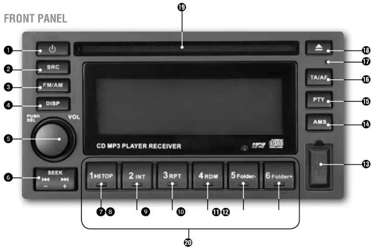
CD/USB - MP3 PLAYER / TUNER power on / off button.
SRC (source) button: source selection among tuner, CD (when inserted), USB (if a USB flash drive is present).
FM/AM button: tuner band selection between FM (frequency modulation, 3 groups: FM1, FM2, FM3) and AM (medium wave amplitude modulation, 2 groups: MW1, MW2).
DISP (display) button: it sequentially changes the (available) information on the display:
- Tuner: radio station, frequency, programme type
Audio CD: the current track and its playing time (TRK) - MP3: automatic sequence of all information the current directory (FOLDER) the current file name (FILE) → the album (ALBUM) the song title (MUSIC) the artist (ARTIST), the current track and its playing time (TRK).
VOL volume control and PUSH SEL button to select parameters.
Turn it clockwise to turn the volume up of the (only) CD/USB - MP3 / tuner.
Turn it counterclockwise to turn the volume down.
When pushed, it changes the parameter to edit (by turning the control):
volume (VOL 0 ÷ 40) → bass (BAS -7 ÷ +7) table (TRE -7 ÷ +7) balance (BAL L7
÷ R7; L7 = left channel only, 0 = centre, R7 = right channel only).
The balance (BAL) control works on the stereo INTERNAL PROGRAM output only.
Leave this set at 0 (centre), in order to send a mono signal (the equal sum of the left and the right channels) to the amplifier.
Push and hold this button for at least 2 seconds to enter the 'function menu' (read the relevant manual section at page 41).
SEEK dual button: (-) = back + (+) forward
TUNER:
- To tune the frequency a 0.05 MHz step up: push and immediately release the forward button
To tune the frequency a 0.05 MHz step down: push and immediately release the back button
Automatic next station search: push and hold the forward button for at least a second
Automatic previous station search: push and hold the back button for at least a second
If the TA (traffic announcements) function is enabled, the automatic search will consider the radio stations broadcasting the TP (traffic programme) identification code only.
AUDIO CD AND MP3 FILES:
To select the next track: push and immediately release the forward button
To restart the current track: push and immediately release the back button
- To select previous tracks: push twice or more times (and immediately release) the back button
- To fast-forward the current track: push and hold the forward button
- To go back ('rewind') the current track quickly: push and hold the back button
The track / folder selection is a cyclical: going ahead, after the last track it comes the first; going back, after the first track it comes the last.
TOP button (audio CD and MP3 files only)
Push and immediately release to switch the pause on/off.
Push and hold to restart the entire audio CD / USB flash drive.
INT (intro) button (audio CD and MP3 files only)
Audio CD: it turns on INT ON / off INT OFF the sequential play of every track intro (10 seconds).
MP3 files: INT DISC sequential play of every track intro (10 seconds) INT FOLD sequential play of the current folder track intros (10 seconds) INT OFF standard play.
RPT (repeat) button (audio CD and MP3 files only)
Audio CD: it turns on RPT ON / off RPT OFF the continuous repeat of the selected track.
MP3 files: RPT TRK continuous repeat of the selected track RPT FOLD sequential continuous repeat of all folder tracks RPT OFF no repeats, standard play.
10 RDM (random) button (audio CD and MP3 files only)
It turns on RDM ON / off RDM OFF the track random play.
1 Folder - button (MP3 files only)
Push and immediately release to skip 10 tracks back (10TRK <). Push and hold to select the previous folder (FOLDER <).
12 Folder + button (MP3 files only)
Push and immediately release to skip 10 tracks forward ( 10TRK >>). Push and hold to select the next folder ( FOLDER >>).
USB port
The insertion of a USB flash drive is automatically detected. Before removing the USB flash drive, switch the source to tuner (or CD) by pushing the SRC button.
14 AMS (auto memory scan) button (tuner only).
Push and immediately release to display and listen to (about 5 seconds each) all the radio stations stored of the same band.
Push and hold to automatically scan and store some radio stations (18 in the FM band, 12 in the MW band), which signal is received properly (and better than other stations).
IMPORTANT: the auto scan erases all preferred radio stations previously stored!
If the TA (traffic announcements) function is enabled, the automatic scan will consider the radio stations broadcasting the TP (traffic programme) identification code only.
The AMS button can be used to search MP3 files (see the 'MP3 file search' section).
15 PTY (programme type) button (FM tuner only)
Radio stations with RDS ('Radio Data System') service can broadcast a programme type identification signal.
Push the PTY button once to search a radio station that broadcasts a particular kind of music; push it twice to search a radio station that broadcasts a particular speech programme; push again to cancel the search.
The search automatically begins 2 seconds later (since the last PTY button push): if no station is broadcasting the desired music kind / speech programme, NO PTY will be displayed.
The PTY button is disabled when the TA (traffic announcements) function is switched on.
The choice of the music kind / speech programme is made by pushing (once or twice sequentially) one of the button marked from 1 to 6 (20):
| BUTTON no. | MUSIC KIND | SPEECH PROGRAMME |
| 1 | POP M (pop music) NEWS | |
| 1 | ROCK M (rock music) AFFAIRS | |
| 1 | — INFO | |
| 2 | EASY M (easy listening music) SPORT | |
| 2 | LIGHT M (light classical music) EDUCATE (educational programmes) | |
| 2 | — DRAMA | |
| 3 | CLASSIC M (classical music) CULTURE | |
| 3 | OTHER M (other music kinds) SCIENCE | |
| 3 | — VARIED | |
| 4 | JAZZ M (jazz music) WEATHER | |
| 4 | COUNTRY M (country music) FINANCE | |
| 4 | — CHILDREN (children's programmes) | |
| 5 | NATION M (national music) SOCIAL (social affairs) | |
| 5 | OLDIES M (oldies) RELIGION | |
| 5 | — PHONE IN (forums) | |
| 6 | FOLK M (folk music) TRAVEL | |
| 6 | — | LEISURE |
| 6 | — | DOCUMENT (documentary) |
16 TA/AF (traffic announcements / alternative frequency) button (FM tuner only)
Some radio stations with RDS ('Radio Data System') service periodically provide traffic information. These stations can be identified by the TP indication on the display.
If this button is pushed and immediately released:
- When tuned to a radio station that provides traffic information, it will enable (TA is displayed) or disable the traffic information reception mode that has a particular preset volume (read the 'FUNCTION MENU' section).
- When tuned to a radio station that does not provide traffic information, according to the setting of the FUNCTION MENU TA parameter, it will start the automatic search of a station providing traffic information (TA SEEK is displayed) or it will be just displayed that this service is not currently available (NO TA/TP).
If the TA (traffic announcements) function is enabled, the band scan (either manual by pushing the SEEK button or automatic by pushing the AMS button), will consider the radio stations broadcasting the TP (traffic programme) identification code only.
If this button is pushed and held for a few seconds, the 'alternative frequency' function turns on (AF is displayed) / off. This function (when enabled) allows the automatic search of an alternative station having a similar programme to the one selected when the signal reception degrades.
If the alternative frequency function is not available, the AF indication on the display will blink.
EON (enhanced other networks) If EON data are received (EON is displayed), TA and AF functions will be enhanced:
- TA traffic announcements will be received from both the current station and others.
- AF RDS frequency list will be always kept updated (EON data memory) for the alternative station selection.
17 RESET button (using a small pin only) used only in case the CD/USB - MP3 player / tuner does not work properly or for initializing.
18 CD EJECT button.
Slot for the compact disc insertion (note: insert only 1 disc at a time).
20 1 ÷ 6 buttons: 6 radio station selection / memory storing per each group (FM1, FM2, FM3, MW1, MW2). Push a button and immediately release it to select a radio station (previously stored in that memory location). Push and hold a button to store the current radio station on that memory location (the location number is indicated in the bottom right-hand corner of the display).
FUNCTION MENU
Push and hold (for some seconds) the 5 PUSH SEL button (/ VOL control) to enter the 'function menu'; wait for a few seconds without pushing it to exit automatically. Every following button push changes the parameter that can be edited (turn the control to change the value):
TA VOL-EOLOB>TA RETURN VOL (A-VOL)
TA VOL: traffic announcement preset volume (4÷36).
EQ: music preset equalization
ROCK POP JAZZ CLASSIC EQ OFF (no equalization).
LOUD (Loudness) : ON / OFF
1 Loudness: is a simple way to improve music listening at a low volume level, bass and treble tones are both adjusted to compensate for the poor sensitivity of the human ear at audible frequency range extremities.
TA: when trying to enable the TA (traffic announcements) function when tuned to a radio station that does not provide this service, the options are:
- SEEK: to search automatically a radio station providing traffic announcement information.
- ALARM : to display NO TA/TP only (service not available).
RETURN: time limit setting for the automatic search TA SEEK of radio stations providing traffic information. Options are: 45 seconds (RETURN_S) or 3 minutes (RETURN_L).
VOL : CD/USB - MP3 player and tuner initial volume option (when turning on):
LAST: the same volume level set before turning the device off.
- ADJ: a preset volume level defined by the following parameter A-VOL.
A-VOL (this parameter is available only if the previous VOL is set to ADJ): volume level (0÷ 40) of the CD/USB - MP3 player and tuner when turning on.
NOTES ABOUT MP3 FILES
MP3: means MPEG Audio Layer 3 and refers to an audio compression type.
This player reads MP3 files on CD-ROM, CD-R or CD-RW discs and USB flash drives; if available, track titles, artists and albums are displayed (ID3 TAG).
CD-R - CD-RW discs formatted as 'packet write' mode are not supported.
The file extension must be .mp3.
The max. directory (/ folder) level is 8, including the 'root'.
Max. 256 MP3 files per source.
If a CD includes both audio tracks and MP3 files, only the audio tracks will be played.
- When playing an MP3 file with variable bit rate ('VBR'), the displayed time might not be correct (and also the INT function may not work properly).
It is advisable to use MP3 files having a sampling frequency of 44.1kHz and a fixed bit-rate of at least 128 kbps (if higher, for instance 192 kbps, the sound quality will be better).
USB 1.1 support and also 2.0 (but at the same speed of USB 1.1)
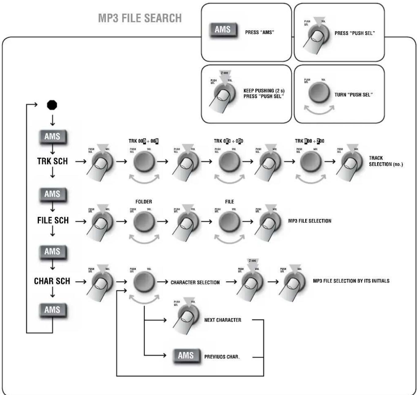
MP3 FILE SEARCH
REMOTE CONTROL
The remote control uses a CR 2025 (3 V) lithium battery. The battery may need replacing when the control does not operate correctly or for example, it is necessary to get closer to the ES 3160 to restore operation.
To replace the battery: open the battery holder on the rear side by moving the lock part.
Ensure the battery polarity is correct.
When using the remote control, hold it in the proper way and direct it at the ES 3160.
ON-OFF It turns on / off the CD/USB - MP3 player / tuner (only).
SEL Same function of the PUSH SEL button (see 5) for the parameter selection.
VOL (+) (-) Same function of the VOL volume control (see 5).
- (back) (forward) Same function of the SEEK dual button (see 6).
SRC Same function of the SRC button (see 2).
AMS Same function of the AMS button (see 14).
TA Same function of the TA/AF button (see 16).
AF/REG (see below*)
- PTY Same function of the PTY button (see 15).
BAND Same function of the FM/AM button (see 3).
- II TOP (1) Same function of the III TOP button (see 7).
- INT (2) Same function of the INT button (see 8).
RPT (3) Same function of the RPT button (see 9
RDM (4) Same function of the RDM button (see 19).
The 1÷ 6 keys can also be used to select / store 6 radio stations (see 20).
DISP Same function of the DISP button (see 4).
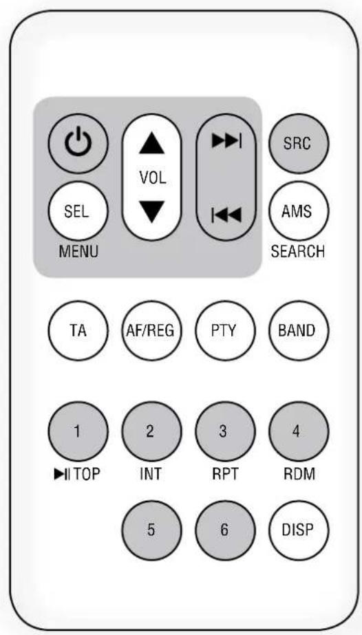
- AF / REG 'alternative frequency / region' (FM tuner, stations with RDS only).
Push and immediately release to enable / disable the 'alternative frequency' function (AF is displayed).
This function (when enabled) allows the automatic search of an alternative station having a similar programme to the one selected when the signal reception degrades.
Push and hold to switch on / off the 'region' option (related to the 'alternative frequency' function):
- REG ON (the selected station can only be replaced by another of the same region).
- REG OFF (the selected station can be replaced by any other).
ERROR CODES
ERR-1 and ERR-2 Push and hold (at least 2 seconds) the EJECT button to eject the compact disc. If the CD is not ejected, push the RESET button by using a pin and then EJECT (2 seconds) again.
Should not be possible to eject the CD, please consult your dealer (or an authorized service centre).
ERR-3 The compact-disc has been wrongly inserted upside down.
ERR-4 The compact disc format is not supported (or data / files are not correct).
LOUDSPEAKER CONNECTION
Use 1 output only - DO NOT MIX 100/70 V and 4 Ω CONNECTIONS.
70/100VCONSTANT VOLTAGE OUTPUTS
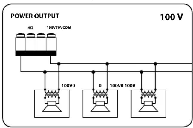

Each loudspeaker shall have a line transformer with the input voltage equal to the line voltage (70 / 100V)
The loudspeaker total power shall not be higher than the amplifier maximum power.
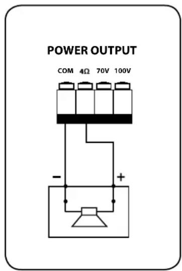
LOW IMPEDANCE OUTPUT (4 Ω)
The loudspeaker total impedance shall not be lower than 4
Note: a total impedance equal to 4 allows the amplifier maximum power delivery. A higher impedance leads to a reduction of the power delivered by the amplifier (e.g. 8Ω: approx. 12 power, 16Ω: approx. 14 power). An impedance lower than 4Ω overloads the amplifier.
- Loudspeaker models shall be chosen by considering the max. power (160 W on a 4 Ω load) that the amplifier can deliver.
- Loudspeaker line should be as short as possible, long cables may need large wire cross-sections.
- Do not use, at the same time, both the low impedance output (4 Ω) and the constant voltage output (70V or 100V), as this overloads the amplifier.
POWER SUPPLY VOLTAGE CHANGE
IMPORTANT: This manual section concerns qualified personnel only. The following instructions are to be ignored by the user.
Make sure the device is not connected to the mains (unplug the power supply cable).
Remove the lid.
The power supply circuit is under the ventilation screen (see picture 1), which can be removed by unscrewing the 2 screws.
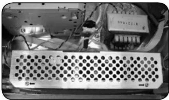
PICTURE 1
The voltage change connector is highlighted by a square.
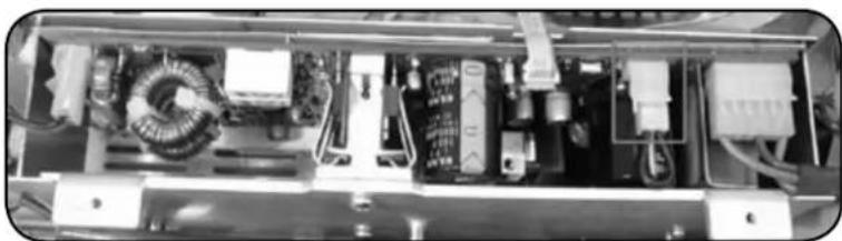
PICTURE 2
If the mains voltage is 230V set the connector to the 230Vac position (see the picture 3), according to the PCB indication (looking at the connector front, the central pin is connected to the right one).
PICTURE 3
If the mains voltage is 115V , set the connector to the 115 Vac position (see the picture 4), according to the PCB indication (looking at the connector front, the central pin is connected to the left one).
PICTURE 4
Refit the power supply circuit metallic screen and the device lid.
Before connecting the device to the mains, make sure that the fuse (inside the IEC power supply connector of the rear panel, see 26) is the correct current rating for the mains voltages (read the fuse indication below the connector).
SPECIFICATIONS
AMPLIFIER
Output power 160 W (RMS)
Frequency response 50 Hz ÷ 13.5 kHz
Signal/noise ratio
- Mic (1 ÷ 4) 60 dB
-Aux 80 dB
Distortion (at 1 kHz, nominal power) < 0.3%
AUX INPUT TONE CONTROLS
-Bass ±8dB@80Hz
- Treble ± 8 dB @ 13 kHz
PRESENCE control (inputs 1 ÷ 4) + 10 dB @ 2.15 kHz
High-pass filter (inputs 1 ÷ 4 ) 150 Hz
INPUT SENSITIVITY / IMPEDANCE
MIC (1 ÷ 4) Balanced - 50 dBu / 10 kΩ
MIC PHANTOM (1 ÷ 4) Balanced -21 dBu /5 kΩ
LINE (1÷ 4) Balanced 0 dBu (max. + 16 dBu) / 10 kΩ
AUX INPUT Adjustable -6÷ +13 dBu/20kO
AUX OUTPUT LEVEL / IMPEDANCE
(pre/music on hold) -1 dBu/600Ω
Phantom power' voltage / current 32 V/18 mA
LOUDSPEAKER OUTPUTS (POWER: 160 W)
Low impedance 4Ω(25V)
Constant voltage 70 V (31 Ω) / 100 V (62 Ω)
RADIO
FM range 87.5÷108MHz
FM frequency response 30 Hz ÷ 15 kHz
FM channel separation (1 kHz) ≥ 30 dB
FM Intermediate rejection ≥ 70dB
FM Image rejection ≥ 50 dB
FM signal / noise ratio ≥ 55 dB
AM (MW) range 522 ÷ 1620 kHz
Antenna input 75Ω-Coaxial
AUDIO CD
Frequency response 20 Hz ÷ 20 kHz
Signal/noise ratio 86 dB
Total harmonic distortion (1 kHz) < 0.2%
Channel separation ≥ 60dB
PROTECTIONS
Amplifier Short circuit, thermal
Load DC Offset Delay, fuse
Power supply fuses
GENERIC
Operating voltage 115-230V/50-60Hz
Power (consumption) 350 W
Dimensions (w, h, d) 444 mm, 127 mm, 345 mm
Net weight 8 kg
EXAMPLE OF CONNECTIONS
INDEX
CONSIGNES DE SECURITE page 49
DESCRIPTION page 51
FACE AVANT page 51
PANNEAU ARRIERE page 53
UTILISATION page 56
REMARQUES RELATIVES AUX DISQUES COMPACTS
EON (Enhanced Other Networks)
- Treble ± 8 dB @ 13 kHz
Voltage constant 70 V (31 Ω) / 100 V (62 Ω)
RADIO
Bande FM 87.5÷108MHz
Distorsion harmonique totale (1 kHz) < 0.2%
Charge DC Offset Delay, fuse
Except possible errors and omissions.
RCF S.p.A. reserves the right to make modifications without prior notice.