PL 70EN - Pregnant RCF - Free user manual and instructions
Find the device manual for free PL 70EN RCF in PDF.

| Product Type | Passive loudspeaker |
| Woofer | 10" (254 mm) with 2.5" voice coil |
| Tweeter | 1" (25 mm) titanium compression driver |
| Frequency Response | 60 Hz - 20 kHz (-3 dB) |
| Power Handling (AES) | 200 W RMS |
| Peak Power | 800 W |
| Sensitivity (1W/1m) | 96 dB SPL |
| Maximum SPL | 122 dB peak |
| Impedance | 8 ohms |
| Connectors | 2x SpeakON NL4MP |
| Enclosure Material | 15 mm plywood |
| Grille | Powder-coated steel with protective foam |
| Dimensions (HxWxD) | 520 x 324 x 310 mm |
| Weight | 15.5 kg |
| Mounting | Integrated pole mount (35 mm) and flying points |
| Color | Black textured paint |
| Application | Portable PA, fixed installation, stage monitoring |
| Warranty | 2 years (RCF standard) |
| Safety Features | Rubber feet, thermal protection with PTC |
| Maintenance | Clean with dry cloth; do not use solvents |
| Spare Parts Availability | Contact RCF authorized service centers |
Frequently Asked Questions - PL 70EN RCF
User questions about PL 70EN RCF
0 question about this device. Answer the ones you know or ask your own.
Ask a new question about this device
Download the instructions for your Pregnant in PDF format for free! Find your manual PL 70EN - RCF and take your electronic device back in hand. On this page are published all the documents necessary for the use of your device. PL 70EN by RCF.
USER MANUAL PL 70EN RCF
USER MANUAL MANUALE D'USO
PL 70EN
FLUSH-MOUNT CEILING LOUDSPEAKER IN COMPLIANCE WITH EN 54-24 STANDARD
DIFFUSORE ACUSTICO PER CONTROSOFFITTO CONFORME ALLA NORMA EN 54-24
INDEX INDICE

ENGLISH
SAFETY AND OPERATING PRECAUTIONS 4
DESCRIPTION 6
INSTALLATION 6
CONNECTION 8
NOTES ABOUT CONSTANT VOLTAGE SYSTEMS 11
SPECIFICATIONS | 12
ITALIANO
AVVERTENZE PER LA SICUREZZA E PRECAUZIONI D'USO | 14
DESCRIZIONE 16
INSTALLAZIONE 16
COLLEGAMENTO 18
NOTE SUI SISTEMI A TENSIONE COSTANTE | 21
DATI TECNICI 22
IMPORTANT NOTES
Before connecting and using this product, please read this instruction manual carefully and keep it on hand for future reference. This manual is to be considered an integral part of this product and must accompany it when it changes ownership as a reference for correct installation and use as well as for the safety precautions.
RCF S.p.A. will not assume any responsibility for the incorrect installation and / or use of this product.
SAFETY AND OPERATING PRECAUTIONS
- All the precautions, in particular the safety ones, must be read with special attention, as they provide important information.
- Loudspeaker lines (amplifier outputs) can have a sufficiently high voltage (i.e. 100-70 V) to involve a risk of electrocution: never install or connect this loudspeaker when the line is alive.
- Make sure all connections have been made correctly and the loudspeaker input voltage is suitable for the amplifier output.
- Protect loudspeaker lines from damage. Make sure they are positioned in a way that they cannot be stepped on or crushed by objects.
- Make sure that no objects or liquids can get into this product, as this may cause a short circuit.
- Never attempt to carry out any operations, modifications or repairs that are not expressly described in this manual.
Contact your authorized service centre or qualified personnel should any of the following occur:
- The loudspeaker does not function (or works in an anomalous way).
- The cable has been damaged.
- Objects or liquids have got into the unit.
-
The loudspeaker has been damaged due to heavy impacts or fire.
-
Should the loudspeaker emit any strange odours or smoke, remove it from the line after having immediately switched the amplifier off.
-
Do not connect this product to any equipment or accessories not foreseen. For suspended installation, only use the dedicated anchoring points and do not try to hang this loudspeaker by using elements that are unsuitable or not specific for this purpose.
Also check the suitability of the support surface to which the product is anchored (wall, ceiling, structure, etc.) and the components used for attachment (screw anchors, screws, brackets not supplied by RCF etc.), which must guarantee the security of the system / installation over time, also considering, for example, the mechanical vibrations normally generated by transducers.
IMPORTANT NOTES

-
RCF S.p.A. strongly recommends this product is only installed by professional qualified installers (or specialised firms) who can ensure a correct installation and certify it according to the regulations in force. The entire audio system must comply with the current standards and regulations regarding electrical systems.
-
Mechanical and electrical factors need to be considered when installing a professional audio system (in addition to those which are strictly acoustic, such as sound pressure, angles of coverage, frequency response, etc.).
11. Hearing loss
Exposure to high sound levels can cause permanent hearing loss. The acoustic pressure level that leads to hearing loss is different from person to person and depends on the duration of exposure.
To prevent potentially dangerous exposure to high levels of acoustic pressure, anyone who is exposed to these levels should use adequate protection devices.
When a transducer capable of producing high sound levels is being used, it is necessary to wear ear plugs or protective earphones.
See the technical specifications in the instruction manual for the maximum sound pressure the loudspeaker is capable of producing.
-
To ensure a correct sound reproduction, loudspeaker phase is to be respected (loudspeakers are connected respecting the amplifier polarity). This is important when loudspeakers are installed adjacent one another, for instance, in the same room.
-
To prevent inductive effects from causing hum, noise and a bad system working, loudspeaker lines should not be laid together with other electric cables (mains), microphone or line level signal cables connected to amplifier inputs.
-
The loudspeaker cable shall have wires with a suitable section (twisted, if possible, to reduce inductive effects due to surrounding electro-magnetic fields) and a sufficient electrical insulation. Refer to local regulations since there may be additional requirements about cable characteristics.
-
Install this loudspeaker far from any heat source.
-
Do not use solvents, alcohol, benzene or other volatile substances for cleaning the external parts of this product. Use a dry cloth.
RCF S.P.A. THANKS YOU FOR PURCHASING THIS PRODUCT, WHICH HAS BEEN DESIGNED TO GUARANTEE RELIABILITY AND HIGH PERFORMANCE.
DESCRIPTION

The PL 70EN ceiling loudspeaker is in compliance with EN 54-24 standard. It is equipped with a fire protection steel base and can be installed flush-mounted in false ceilings or panels.
It is particularly suitable for reproducing alarm messages, as it provides particularly intelligible voice reproduction and it is resistant to the high temperatures that can be reached during a fire.
The PL 70EN has the following main features:
- High quality voice reproduction.
- Dual cone loudspeaker, 160 mm (6") diameter, featuring a broad frequency response and dispersion.
- Transformer for connection to constant voltage lines (100 V / 70 V).
- Possibility to select the output power among several values.
- Steel construction, with metal protection grille.
- Fire protection steel base with an attachment system that ensures quick installation.
- Two ceramic terminal strips for connecting the input and output cable (IN/OUT).
- Support for connection terminals that can be removed from the base to facilitate connections.
- Possibility to complete the audio line connection to the terminal strip of the base without installing the loudspeaker.
- Quick system to fix the loudspeaker to the base by means of two springs.
- Earth screws.
- Thermic fuse that prevents damage to the audio line due to heat on the speaker.
INSTALLATION

WARNING: MAKE SURE THAT THE LOUDSPEAKER IS INSTALLED IN A STABLE AND SECURE WAY IN ORDER TO AVOID ANY CONDITIONS THAT MAY BE DANGEROUS FOR PERSONS OR STRUCTURES.
ENSURE THE SUPPORT SURFACE (E.G. FALSE CEILING) HAS THE NECESSARY MECHANICAL CHARACTERISTICS TO SUPPORT THE WEIGHT OF THE LOUDSPEAKER.
BEFORE INSTALLING THE LOUDSPEAKER, CAREFULLY CHECK ALL COMPONENTS TO BE USED AND MAKE SURE THERE IS NO DAMAGE, DEFORMATION, CORROSION AND/OR MISSING OR DAMAGED PARTS THAT COULD REDUCE THE SAFETY OF THE INSTALLATION.
IN OUTDOOR USE, AVOID INSTALLING THE LOUDSPEAKER IN PLACES EXPOSED TO HARSH WEATHER CONDITIONS. THE PL 70EN IS DESIGNED FOR FLUSH-MOUNT INSTALLATION IN FALSE CEILINGS.
BEFORE INSTALLING THE LOUDSPEAKER, MAKE SURE THERE IS SUFFICIENT SPACE BEHIND THE FALSE CEILING PANEL TO HOLD THE SPEAKER: WITH RESPECT TO THE SUPPORT SURFACE OF THE FRONT FLANGE OF THE LOUDSPEAKER, A FREE SPACE 150 MM (C. 6") DEEP IS NECESSARY.

- Drill a hole of diameter 205 mm (8.07") in the false ceiling panel, as shown in figure 1.

text_image
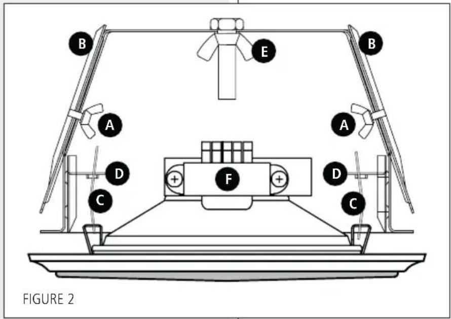
Ø205 mm (8.07") FIGURE 1- Loosen the two wing bolts A (figure 2) that secure the two attachment plates B and move the plates upwards, then secure the two plates B by retightening the two wing bolts A.
- Insert the fire protection base in the hole previously drilled (as shown in figure 1).
text_image
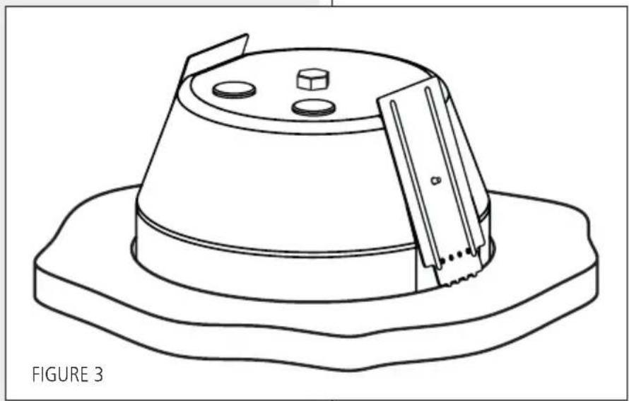
B E B A A D F D C C FIGURE 2- Loosen the two wing bolts A again and move the two attachment plates B downwards to secure the base to the false ceiling (as shown in figure 3). When this operation is complete, retighten the two wing bolts A.
natural_image
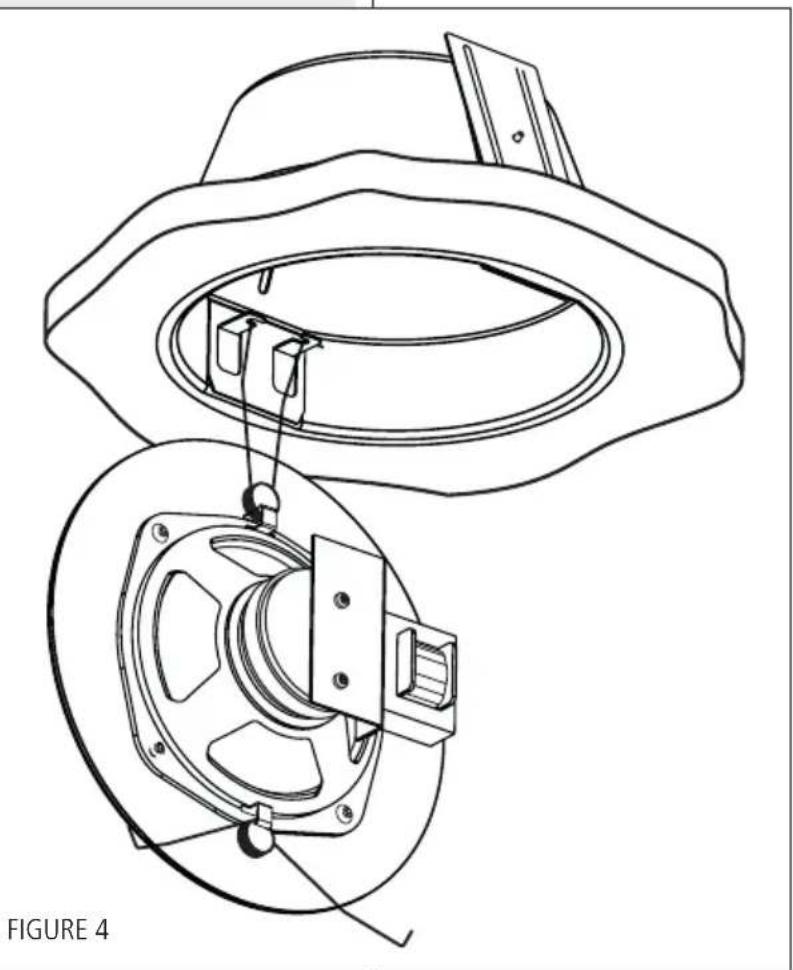
Line drawing of a conical hat with a flat base and three circular indentations, labeled 'FIGURE 3' (no text or symbols on the diagram itself)- Hang the speaker into the base, fitting the ends of one of the two support springs C on the speaker into one of the hooks D on the base (as shown in figure 4).
- Make the electrical connections as described in the next manual section.
- Fit the ends of the other support spring C to the second hook D on the base.
- Push the speaker into the base until the front flange lays against the false ceiling.
natural_image
Technical line drawing of a mechanical component with two views, no text or symbols presentCONNECTION

WARNING: LOUDSPEAKER CONNECTIONS SHOULD BE ONLY MADE BY QUALIFIED AND EXPERIENCED PERSONNEL HAVING THE TECHNICAL KNOW-HOW OR SUFFICIENT SPECIFIC INSTRUCTIONS TO ENSURE THAT CONNECTIONS ARE MADE CORRECTLY AND TO PREVENT ANY ELECTRICAL DANGER. TO PREVENT ANY RISK OF ELECTRIC SHOCK, DO NOT CONNECT LOUDSPEAKERS WHEN THE AMPLIFIER IS SWITCHED ON. BEFORE TURNING THE SYSTEM ON, CHECK ALL CONNECTIONS AND MAKE SURE THERE ARE NO ACCIDENTAL SHORT CIRCUITS. THE ENTIRE SOUND SYSTEM SHALL BE DESIGNED AND INSTALLED IN COMPLIANCE WITH THE CURRENT LOCAL LAWS AND REGULATIONS REGARDING ELECTRICAL SYSTEMS.


text_image
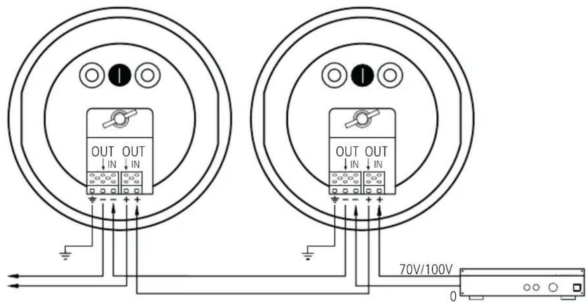
OUT OUT ↓ IN ↓ IN OUT OUT ↓ IN ↓ IN 70V/100V 0FIGURE 5
Connections with the audio line are made by using the two ceramic terminal strips situated inside the base and can be made even without the presence of the speaker, which can be installed at a later time. The IN +/- terminals are used for audio signal input and the OUT +/- terminals (that are directly connected to the corresponding IN +/- terminals) can be used as an output to link additional loudspeakers in parallel (see figure 5).
- Insert cables through the two rubber cable guides I (figure 5) on the base.
- Connect the negative conductor (−) of the audio line (which comes from the amplifier terminal marked −, 0 or COM) to the loudspeaker input IN −.
- Connect the positive conductor (+) of the audio line to the loudspeaker input IN +.
- Follow the same logic to connect the OUT +/- terminals, that can be used to link additional loudspeakers in parallel.
NOTE: TO FACILITATE CONNECTIONS, ESPECIALLY WHEN USING PARTICULARLY RIGID FIRE PROTECTION CABLES, THE CERAMIC TERMINALS CAN BE REMOVED FROM THE BASE BY UNSCREWING THE WING BOLT E (FIGURE 2) THAT SECURES THE TERMINAL SUPPORT.

LINE TRANSFORMER CONNECTION
The line transformer F (figure 2) of the loudspeaker is connected to the terminal strip on the base through the two conductors with FASTON connectors.
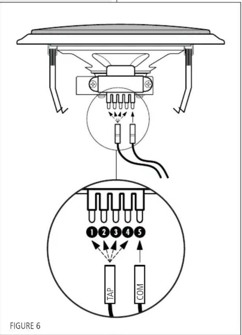
Power selection (see figure 6):
- Connect the FASTON connector marked COM (black wire) to the terminal 5 (COM) on the line transformer of the speaker.
- Connect the FASTON connector marked TAP (red wire) to the terminal of the line transformer marked with the desired power.
| TAP | POWER(100 V) | POWER(70 V) |
| 1 | 0.75 W | 0.375 W |
| 2 | 1.5 W | 0.75 W |
| 3 | 3 W | 1.5 W |
| 4 | 6 W | 3 W |
| 5 | COM | |
- Insert the protective conductor of the local earth system through one of the rubber cable guides I (figure 5) on the loudspeaker base.
- Connect the earth conductor to the terminal strip contact marked with the earth symbol (figure 5).
text_image
FIGURE 6 TAP COMNOTES ABOUT CONSTANT VOLTAGE SYSTEMS

- The loudspeaker input voltage (Vd) shall correspond to the amplifier output voltage (Va).
- The sum of nominal power values (Pd x n) of all loudspeakers connected to the line shall not exceed the amplifier power (Pa).
- Make sure all loudspeakers are connected in phase to ensure a correct sound reproduction.
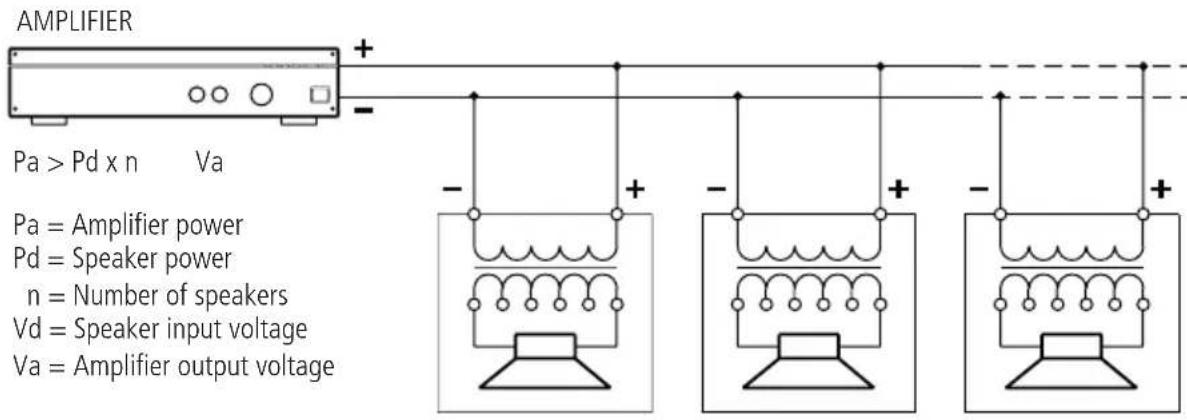
text_image
AMPLIFIER Pa > Pd x n Va Pa = Amplifier power Pd = Speaker power n = Number of speakers Vd = Speaker input voltage Va = Amplifier output voltageFIGURE 7
- Always use cables having wires with an adequate cross-section, considering the cable length and the total loudspeaker power.
- Loudspeaker lines must be kept separated from mains cable, microphone cables or others, in order to avoid inductive phenomena may cause hum or noises.
- Use loudspeaker cables having twisted wires to reduce hum caused by inductive effects due to coupling with electromagnetic fields.
INPUT VOLTAGE: 100 V - (70 V)
POWER (SELECTABLE): 6 W - 3 W - 1.5 W - 0.75 W (power values are halved at 70 V)
INPUT IMPEDANCE: 1.67 kΩ (6 W) - 3.33 kΩ (3 W) - 6.67 kΩ (1.5 W) - 13.33 kΩ (0.75 W)
FREQUENCY RESPONSE: 145 Hz ÷ 20 kHz (-10 dB)
SENSITIVITY: 95 dB (1 W, 1 m)
SOUND PRESSURE LEVEL: 103 dB (6 W, 1 m), 91 dB (6 W, 4 m)
COVERAGE ANGLE (-6 dB): hor.: 180° (500 Hz), 133° (1 kHz), 80° (2 kHz), 159° (4 kHz)
vert.: 180° (500 Hz), 133° (1 kHz), 80° (2 kHz), 159° (4 kHz)
TRANSDUCER: 6" dual-cone
BODY, GRILLE MATERIAL: steel plate
BODY, GRILLE COLOUR: 'Signal white', RAL 9003
FIRE DOME MATERIAL: steel plate
FIRE DOME COLOUR: red
CONNECTOR: ceramic terminal strips
FALSE CEILING CUTOUT SIZE: ∅ 205 mm (8.07")
NET WEIGHT: 2 kg (4.4 lb)
OPERATING TEMPERATURE: -30 ÷ +60^ (-22 ÷ +140^)
DIMENSIONS:
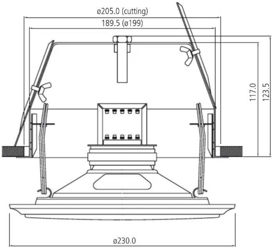
text_image
Ø205.0 (cutting) 189.5 (Ø199) 117.0 123.5 Ø230.0INDICE

AVVERTENZE PER LA SICUREZZA E PRECAUZIONI D'USO 14
DESCRIZIONE 16
INSTALLAZIONE 16
COLLEGAMENTO 18
NOTE SUI SISTEMI A TENSIONE COSTANTE 21
DATI TECNICI 22
IMPORTANTE
natural_image
Technical line drawing of a conical hat with mounting base and side panel (no text or symbols)natural_image
Technical line drawing of a mechanical component with two views, labeled 'FIGURA 4' (no text or symbols on the diagram itself)COLLEGAMENTO

ATTENZIONE: PER IL COLLEGAMENTO DEL DIFFUSORE SI RACCOMANDA DI RIVOLGERSI A PERSONALE QUALIFICATO ED ADDESTRATO, OSSIA PERSONALE AVENTE CONOSCENZE TECNICHE O ESPERIENZA O ISTRUZIONI SPECIFICHE SUFFICIENTI PER PERMETTERGLI DI REALIZZARE CORRETTAMENTE LE CONNESSIONI E PREVENIRE I PERICOLI DELL'ELETTRICITA. PER EVITARE IL RISCHIO DI SHOCK ELETTRICI, NON COLLEGARE IL DIFFUSORE CON L'AMPLIFICATORE ACCESO. PRIMA DI FAR FUNZIONARE IL DIFFUSORE, È BUONA NORMA RICONTROLLARE TUTTE LE CONNESSIONI, VERIFICANDO IN PARTICOLAR MODO CHE NON VI SIANO DEI CORTOCIRCUITI ACCIDENTALI. TUTTO L'IMPIANTO DI SONORIZZAZIONE DOVRÀ ESSERE REALIZZATO IN CONFORMITÀ CON LE NORME E LE LEGGI VIGENTI IN MATERIA DI IMPIANTI ELETTRICI.

text_image
OUT OUT ↓ IN ↓ IN OUT OUT ↓ IN ↓ IN 70V/100V 0FIGURA 5
text_image
Diagram showing connector pinout and wiring connections, including TAP and COM labels with numbered pinsNOTE SUI SISTEMI A TENSIONE COSTANTE

TENSIONE D'INGRESSO: 100 V – (70 V)
Loudspeaker for voice alarm systems for fire detection and fire alarm systems for buildings
PL 70EN
Type A
DoP: 002_14
Other technical data: see operational manual.
Except possible errors and omissions.
RCF S.p.A. reserves the right to make modifications without prior notice.